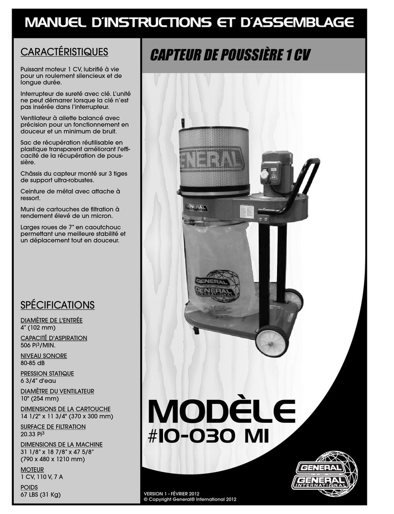
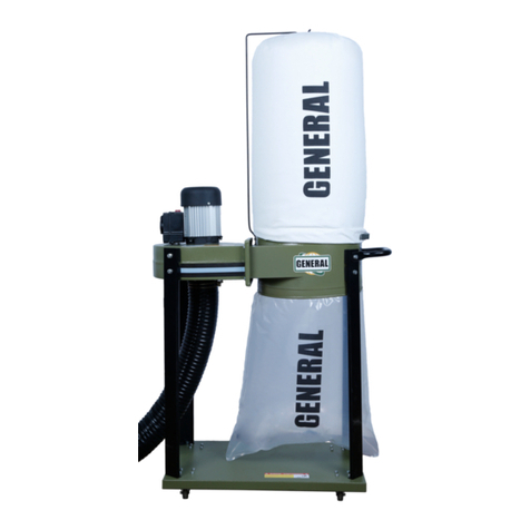
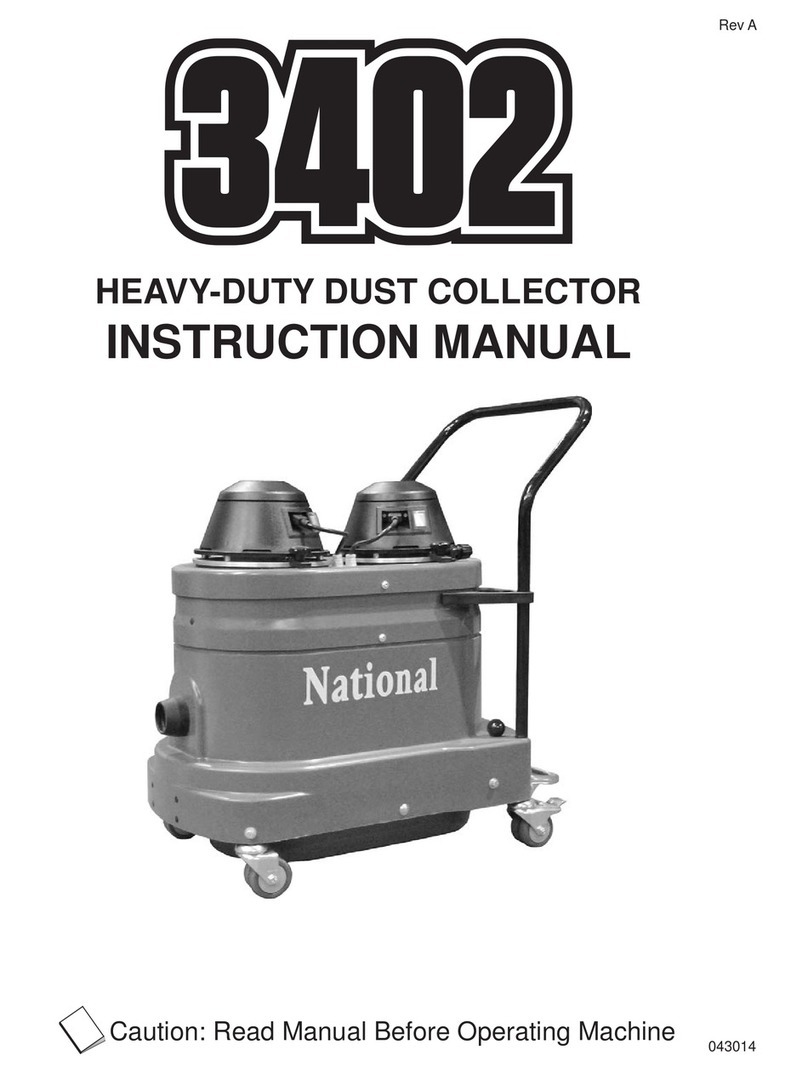
General 10-105 User manual

1
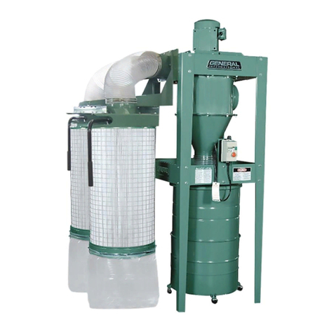
1 1/2 HP Dust Collector
#10-105, #10-105CF & 10-105DAS

2
IMPORTANT SAFETY
INSTRUCTIONS WARNING –To reduce risk of injury:
1. FOR YOUR OWN SAFETY, READ INSTRUCTION
MANUAL BEFORE OPERATING THE TOOL. Learn the
tool’s application and limitations as well as the specific
hazards peculiar to it.
2. KEEP GUARDS IN PLACE and in working order.
3. ALWAYS WEAR EYE PROTECTION.
4. GROUND ALL TOOLS. If tool is equipped with three
prong plug, it should be plugged into a three-hole
electrical receptacle. If an adapter is used to
accommodate a two prong receptacle, the adapter lug
must be attached to a known ground. Never remove the
third prong.
5. KEEP WORK AREA CLEAN. Cluttered areas and benches
invite accidents.
6. DON’T USE IN DANGEROUS ENVIRONMENT. Don’t use
power tools in damp or wet locations, or expose them to
rain. Keep work area well-lighted.
7. KEEP CHILDREN AND VISITORS AWAY. All children and
visitors should be kept a safe distance from work area.
8. MAKE WORKSHOP CHILDPROOF. Use padlocks, master
switches, or remove starter keys.
9. DON’T FORCE TOOL. It will do the job better and be
safer at the rate for which it was designed.
10. USE RIGHT TOOL. Don’t force tool or attachment to
do a job for which it was not designed.
11. WEAR PROPER APPAREL. No loose clothing, gloves,
neckties, rings, bracelets, or other jewelry to get caught
in moving parts. Nonslip footwear is recommended.
Wear protective hair covering to contain long hair.
12. ALWAYS USE SAFETY GLASSES. Wear safety glasses
(must comply with ANSI Z87.1). Everyday eyeglasses only
have impact resistant lenses; they are not safety glasses.
Also use face or dust mask if cutting operation is dusty.
13. SECURE WORK. Use clamps or a vise to hold work
when practical. It’s safer than using your hands and frees
both hands to operate tool.
14. DON’T OVERREACH. Keep proper footing and balance at
all times.
15. MAINTAIN TOOLS IN TOP CONDITION. Keep tools sharp
and clean for best and safest performance. Follow
instructions for lubricating and changing accessories.
16. DISCONNECT TOOLS before servicing and when changing
filters.
17. USE RECOMMENDED ACCESSORIES. The use of
accessories and attachments not recommended by
manufacturer may cause hazards or risk of injury to persons.
18. AVOID ACCIDENTAL STARTING. Make sure switch is in
“OFF” position before plugging in power cord.
19. NEVER STAND ON TOOL. Serious injury could occur if the
tool is tipped or if the fan blade is accidentally contacted.
20. CHECK DAMAGED PARTS. Before further use of the tool,
a guard or other part that is damaged should be carefully
checked to ensure that it will operate properly and perform
its intended function-check for alignment of moving parts,
binding of moving parts, breakage of parts, mounting, and
any other conditions that may affect its operation. A guard
or other part that is damaged should be properly repaired or
replaced.
21. NEVER LEAVE TOOL RUNNING UNATTENDED. TURN
POWER OFF. Don’t leave tool until it comes to a complete
stop.
22. DRUGS, ALCOHOL, MEDICATION. Do not operate tool
while under the influence of drugs, alcohol or any
medication.
23. MAKE SURE TOOL IS DICONNECTED FROM POWER
SUPPLY while motor is being mounted, connected or
reconnected
WARNING:
This product can expose you to chemicals including lead
which is known to the State of California to cause cancer and
birth defects or other reproductive harm. For more
information go to http://www.p65warnings.ca. gov.
WARNING:
Drilling, sawing, sanding or machining wood products
generates wood dust and other substances known to the
State of California to cause cancer. Avoid inhaling dust
generated from wood products or use a dust mask or other
safeguards for personal protection. Wood products emit
chemicals known to the State of California to cause birth
defects or other reproductive harm. For more information
go to http://www.p65warnings.ca. gov/wood.

3
Table of Contents
IMPORTANT SAFETY INSTRUCTIONS ................................................................................... 2
Table of Contents ................................................................................................................ 3
Electrical Requirements ...................................................................................................... 4
Specifications ...................................................................................................................... 5
For Your Own Safety ........................................................................................................... 5
Contents of Shipping Carton ............................................................................................... 6
Tools Required for Assembly .............................................................................................. 6
Assembly ............................................................................................................................ 7
Operating Instructions ........................................................................................................ 10
Changing Bag/Filters ....................................................................................................... 11
Recommended Accessories ................................................................................................ 12
Warranty and Service ……………………………………………………………………………………………………. 13
Parts Breakdown for the 1 1/2 HP Dust Collector with and without Canister ................... 14
1 1/2 HP Dust Collector Parts List ……….............................................................................. 15

4
Electrical Requirements
In the event of a malfunction or breakdown, grounding provides a path of least resistance for electric
current to reduce the risk of electric shock. This tool is equipped with an electric cord having an
equipment-grounding conductor and a grounding plug. The plug must be plugged into a matching outlet
that is properly installed and grounded in accordance with all local codes and ordinances.
Do not modify the plug provided. If it will not fit the outlet, have the proper outlet installed by a
qualified electrician.
Improper connection of the equipment-grounding conductor can result in a risk of electric shock. The
conductor, with insulation having an outer surface that is green with or without yellow stripes, is the
equipment grounding conductor. If repair or replacement of the electric cord or plug is necessary, do
not connect the equipment-grounding conductor to a live terminal.
Check with a qualified electrician or service personnel if the grounding instructions are not completely
understood, or if in doubt as to whether the tool is properly grounded.
Use only three wire extension cords that have three-prong grounding plugs and three-pole receptacles
that accept the tool’s plug.*
Repair or replace a damaged or worn cord immediately.
This tool is intended for use on a circuit that has an outlet that looks the one illustrated in Figure A
below. The tool has a grounding plug that looks like the grounding plug as illustrated in Figure A below.
A temporary adapter, which locks like the adapter as illustrated in Figures B below, may be used to
connect this plug to a two-pole receptacle, as shown in Figure B if a properly grounded outlet is not
available.** The temporary adapter should only be used until a properly grounded outlet can be
installed by a qualified electrician. The green colored rigid ear or tab, extending from the adapter, must
be connected to a permanent ground such as a properly grounded outlet box.
* Canadian electrical codes require extension cords to be certified SJT type or better.
** Use of an adapter in Canada is not acceptable.
I
rawings
wings

5
Specifications
Model Number ............................................................................. 10-105 & 10-105CF
Stock Number ............................................................................... 10-105 & 10-105CF
Dust Port Inlet…………………………………………………………………………….1-6” or 2-4”
Bag Filter ....................................................................................... 2 Micron
Canister Filter ............................................................................... 1 Micron
Overall Dimensions (L x W x H/in) .................................................38”x 31 ½” x 76”
Sound Rating @ 3ft ....................................................................... High Speed 80-85 dB
Air Flow Capacity........................................................................... High Speed 1250 CFM
Blower Wheel Diameter............................................................... 12 ¾”
Static Pressure …………......................................................... 9”of Water
Motor ............................................................................................1 1/2 HP, 110/220V, 60Hz, 1 PH, 14/7 A
Weight ...........................................................................................106 lbs. CF unit 130 lbs.
Shipping Weight ............................................................................112 lbs. CF unit-140 lbs.
For Your Own Safety
1. Read and understand instruction manual before installing or operating air cleaner.
2. To reduce the risk of injury disconnect the dust collector from the power source (unplug) before
servicing or changing bags or Canister filter.
3. Do NOT use this Dust Collector for other than its intended use.
4. Make certain the switch is in the OFF position before connecting the machine to the power supply or
cleaning.
5. To reduce the risk of electrical shock, do not expose dust collector to water or rain.
6. Make certain the machine is properly grounded.
7. Wear ear protectors (ear plugs or muffs) & approved safety glasses/face shield during extended
periods of operation.
8. To avoid a potentially dangerous situation, do not use this equipment to filter flammable vapors or
smoke. This dust collector is designed and intended for the collection of wood dust only. It is neither
designed nor intended for any other purpose whatsoever.
9. Failure to comply may result in serious injury and / or property damage.
10). Keep the floor around the machine clean and free of scrap material, oil & grease.
110. Check for damaged parts before/after use.
The above specifications were current at the time this manual was published, but because of our policy
of continuous improvement, General reserves the right to change specifications at any time and without
prior notice, without incurring obligations.

6
Contents of Shipping Carton
1 Drum
1 Collection Body and Motor Assembly
1 Canister Filter (CF Model ONLY)
1 “Snap Ring”
1 Belt Clamp
3 Vertical Support Rods
4 Casters
1 Bag Hanger
1 “Y” Fitting Inlet with End Cap
1 5” Hose
2 Hose Clamp
1 Collector Bag
1 Filter Bag
1 Dust Outlet
1 Gasket
1 Base Plate
1 Adhesive Foam Gasket
1 10-12 MM Combination Wrench
1 Allen Key
1 Phillips Head Screw
38 Hex Head Flange Bolt
1 Manual and Warranty Card
Tools Required for Assembly
1 Flat Piece of Wood, (such as a ruler)
1 Medium Phillips Screwdriver
1 10-12 mm Open End Wrench or Adjustable Wrench
1 Extra person to help with lifting

7
ASSEMBLY INSTRUCTIONS
• SERIOUS PERSONAL INJURY COULD OCCUR IF YOU CONNECT
THE MACHINE TO THE POWER SOURCE BEFORE YOUR HAVE
COMPLETED THE SET UP PROCESS. DO NOT HOOK-UP THE MACHINE
TO A POWER SOURCE UNTIL INSTRUCTED TO DO SO.
• BE SURE TO READ AND UNDERSTAND THIS ENTIRE MANUAL. • USE
CAUTION AND WEAR GLOVES WHEN HANDLING METAL PARTS SUCH
AS THE BELT CLAMPS, WHICH CAN CUT IF HANDLED CARELESSLY.
• THE SOUND LEVEL OF THIS MACHINE IS RATED AT APPROXIMATELY
80-85 DB DURING OPERATION. MAKE SURE THAT ADEQUATE
HEARING PROTECTION IS USED AND THAT THE OVERALL SOUND
LEVEL WITHIN THE WORKING ENVIRONMENT IS TAKEN INTO
CONSIDERATION.
1. Attach the 4 casters to the underside of the base
using 4 hex flange head bolts per caster, then
tighten the bolts using the supplied 8-10 mm
combination wrench. (Fig.1)
2. NOTE: Help with lifting will be needed at this
time. The fan/ motor assembly is heavy - do not
overexert. Turn the base back over (right side
up) and place the fan/motor assembly on the
plate. Line up the mounting holes and attach the
assembly to the base using 4 hex head bolts, 2 on
each side. (Fig.2)
3. Place rubber gasket on top of motor housing
aligning holes in gasket with holes in motor
assembly. (Fig 3)
4. Place the connector on the gasket and secure in
place using 8 bolts, in pre tapped holes. Tighten
bolts. (Fig. 4)
NOTE: Do not overtighten the bolts or the
threaded holes in the base will strip and/or the
gasket will squeeze out and the outlet will
crack.
Fig.1
Fig. 2
Fig. 3
Fig. 4

8
6. Attach & Tighten 2 support rods, to base, using 2 hex
bolts for each rod. (Fig. 5)
7. With the help of an assistant, line up the holes in the
drum assembly with the holes in the support rods and
attached with 2 Hex nut bolts. (Fig.6)
8. Place gasket in between connector & Drum then
connect together with 8 hex nut bolts. (Fig.7)
9. Fit the hose inlet (“Y” fitting) on the fan/motor
assembly and secure it in place with the supplied Phillips
head screw. (Fig. 8)
Fig. 5
Fig. 6
Fig. 7
Fig. 8

9
Filter Bag Assembly
If you purchased a 10-105 Dust Collector, this section
describes the assembly and installation of the contents of
the Filter Bag Kit.
Filter Bag Installation
1. Attach bag hanger to backside of drum by
removing 2 hex nuts that connect the support
rods to the drum and slide bag hanger bracket in
between drum & support rod and tighten. (Fig. 9)
2. Slide the filter bag loop over the hanger hook.
3. Feed the retainer strap through the loops on the
filter bag and fasten to the collector housing (Fig.
10)
Collector Bag Installation
1. Place plastic bag inside “snap ring” and fold the
bag over the ring approximately 3 inches. (Fig. 11)
2. Squeeze snap ring in the middle & insert the snap
ring and the collector bag into the bottom of the
housing at an angle. (Fig. 12)
3. Pull down on the snap ring to make sure it seats,
“snaps”, into place in the housing, and that
the plastic bag hangs down approximately 3
inches so that there are no air leaks.
4. Position the plastic window in front so that you
can easily see when the collector bag is full.
Canister Kit Assembly
If you purchased Model #10-105-CF Dust Collector, this
section describes the assembly and installation of the
contents of the Canister Kit.
Canister Filter 1. Mount the handle onto the canister filter
with hex nut, flat washer, and a lock washer. (Fig. 13)
2. Mount the canister filter on top of the collector housing
and tighten the knobs on the canister filter. (Fig. 14)
After completing the filter bag and collector bag
installation, proceed to Operational Instructions &
Electrical Connections.
Fig. 9
Fig. 10
Fig. 11
Fig. 12
Fig. 13
Fig.
14

10
Operating Instructions
WARNING:
Electrical Connections All electrical connections must be
done by a qualified electrician. All adjustments or repairs
must be done with the dust collector disconnected from
the power source, unplugged. Failure to comply may
result in serious injury!
The #10-105/#10-105CF dust collectors are rated at
110/220V, Prewired 110V. Use a plug and outlet rated at
least 20 amps. The circuit for the machine should also be
protected by a minimum 20 amp circuit breaker or fuse.
Keep in mind that a circuit being used by other machines,
tools, lights, heaters, etc. at the same time will add to the
electrical load.
A dedicated circuit to the dust collector will give you the
best results since dust collectors are generally used at the
same time other tools are running. Turning the Machine
On & Off This machine is intended for indoor use only. All
Models Before hooking up to the power source, make
sure that the switch is in the off position
ON/OFF SWITCH
The model 10-105M1/10-105CF M1 Dust collector is
equipped with a simple “rocker style” On/Off switch
featuring a removable lock out safety key.
To prevent unauthorized use or unintentional start-up,
remove the safety key and store it in a safe place when-
ever the dust collector is not in use.
To start the dust collector, insert the safety key and pull
up the switch. To stop the machine, push down on the
power switch.
WARNING:
Make sure the switch is in the “OFF” position before
plugging in the power cord.
Remove the switch key whenever the dust collector is not
in use. Place it in a safe pace and out of the reach of
children.
Picture of switch in ON position.
Picture of switch in OFF position
Picture of Safety Key removed (Prevents
start-up when removed)

11
MAINTENANCE & SERVICING
Make sure the switch is in the “OFF” position and unplug the unit
from the power source before performing any maintenance.
This machine operates on 110V; if you suspect any electrical problems call a
qualified electrician to do the verification of the electrical circuit or the
machine If you need further help with your dust collector contact your
GENERAL distributor or our Technical Service Department at 1-888-664-
0449.
Cleaning the Filter Bag: 10-105.
CAUTION: Wearing a particle mask or respirator for protection
against fine dust particles during cleaning is highly recommended.
During first use and after cleaning, the filter bag may allow some dust to
escape. This is normal and will stop after a short period of time.
Clean both the filter and collector bags frequently to keep the collector's
performance at its optimum. To clean:
1. Disconnect the machine from the power source.
2. Unhook the filter bag from the hanger and shake the bag so that the
majority of the dust falls into the collector bag.
3. Loosen the retaining strap, and remove the filter bag from the housing.
4. Turn the bag inside out and clean.
5. Turn the bag outside in and re-attach to the housing using the retainer
strap to secure.
Removing the Collector Bag: #10-105/#10-105CF
1. Disconnect the machine from the power source.
2. Remove the collector bag by pushing the ring of the collector bag
upwards and pulling the bag out at an angle.
3. Empty the contents into an appropriate container.
4. Turn the bag inside out and clean.
5. Turn the bag outside in and insert into the housing. To replace the
collector bag, refer to Collector Bag Installation on page 11. Use the proper
type hose to connect the dust collector to the machine being operated.
Dryer vent hose is not acceptable for this purpose. Contact your nearest
General distributor for the full line of General Dust Collector Hoses and
Accessories. Customize your installation and obtain maximum performance
with General dust hoods, hoses, clamps, fittings, and blast gates.
Cleaning the Filter: #10-105CK
WARNING Never perform maintenance on this machine
before turning switch off and removing plug from power source.
Failure to comply may cause serious injury! Clean both the canister
filter and collector bags frequently to keep the collector's
performance at its optimum. To clean the filter, turn the handle a
couple of rotations so the dust falls into the collection bag.
Removing the Collector Bag: #10-105CF
CAUTION: Wearing a particle mask or respirator for
protection against fine dust particles during cleaning is highly
recommended.
1. Disconnect the machine from the power source outlet.
2. Remove the collector bag by pushing the ring of the collector bag
upwards at an angle and pulling the bag and snap ring out.
3. Empty the contents into an appropriate container. To replace the
collector bag, refer to the Collector Bag Installation on page 12.
Motor
Make frequent inspections of the motor fan and
blow out (with low pressure air hose) or vacuum
any accumulation of foreign material in order to
maintain normal motor ventilation.
Connecting the Dust Collector to a Machine
Use the proper type hose to connect the dust collector to the
machine being operated. Dryer vent hose is not acceptable for this
purpose. Contact your nearest General distributor for the full line of
General Dust Collector Hoses and Accessories. Customize your
installation and obtain maximum performance with General dust
hoods, hoses, clamps, fittings, and blast gates.
Grounding the Dust Collection System
The dust collection system includes the dust collector and the hose,
or ductwork you use to connect the tools. The dust collector is
grounded through the ground wire in the cord. The hose or
ductwork you use to connect the tool to the dust collector must
also be grounded.

12
Warranty Statement and Policy
Commercial General™ (Green Line) & Excalibur™ (Black Line) branded products: 3 -YEAR LIMITED
WARRANTY All products are warranted for a period of 3 years (36 months) from the date of purchase.
General™ agrees to repair or replace any part or component which upon examination, proves to be
defective in either workmanship or material or parts and labor to the original purchaser during this 3-
year warranty period, subject to the “conditions and exceptions” as listed below. Repairs made without
the written consent of General will void the warranty
EXTEND YOUR WARRANTY: Register your new General™ or Excalibur™ within 60 days of your purchase
and get an extended 2 years, for a total of 5 years, of warranty coverage.
Go to www.general.ca/warranty/registration
DISCLAIMER: Because we are committed to making constant improvements, General™ reserves the
right to make changes to components, parts or features of this unit as deemed necessary, without prior
notice and without obligation to install any such changes on previously delivered units. Reasonable care
is taken at the factory to ensure that the specifications and information in this manual corresponds with
that of the unit with which it was supplied.
TO FILE A CLAIM: To file a claim under our Standard 3 -year Limited Warranty, all defective parts,
components or machinery must be returned freight or postage prepaid to General™, or to a nearby
distributor, repair center or other location designated by General™. For further details call our service
department at 1-844-877-5234 or info@gipowerproducts.com Along with the return of the product
being claimed for warranty, a copy of the original proof of purchase and a “letter of claim” must be
included (a warranty claim form can also be used and can be obtained, upon request, from General™ or
an authorized distributor) clearly stating the model and serial number of the unit (if applicable) and
including an explanation of the complaint or presumed defect in material or workmanship.
CONDITIONS AND EXCEPTIONS: This coverage is extended to the original purchaser only. Prior warranty
registration is not required but documented proof of purchase, i.e. a copy of original sales invoice or
receipt showing the date and location of the purchase as well as the purchase price paid, must be
provided at the time of claim. Warranty does not include failures, breakage or defects deemed after
inspection by General™ to have been directly or indirectly caused by or resulting from; improper use, or
lack of or improper maintenance, misuse or abuse, negligence, accidents, damage in handling or
transport, or normal wear and tear of any generally considered consumable parts or components.
Repairs made without the written consent of General™ will void all warranty. This five-year warranty
does not cover products used for commercial, industrial or educational purposes. The warranty term for
these claims will be limited to a two-year period.

13
Electrical diagram for DAS units.

14
Schematic for #10-105 Dust Collector

15
Parts Breakdown for #10-105
NO
PART NO.
DESCRIPTION
SPECIFCATIONS
QTY
1
10105-01
CASTER
4
2
10105-02
HEX.HEAD BOLT
5/16"×1/2"L
40
4A
10105-04A
BASE PLATE
1
5
10105-05
PAN HEAD SCREW
3/16"×3/8"L
12
6A
10105-06A
INLET COVER
1
7A`
10105-07A
CAP SCREW
M6×16MM L
1
9
10105-09
WASHER
1
10A
10105-10A
FAN
1
11A
10105-11A
COLLECTOR BODY
1
12
10105-12
WASHER
5/16"
8
13
10105-13
PAN HEAD SCREW
3/16"×3/8"L
1
15
10105-14
HEX.HEAD BOLT
5/16"×1"L
4
17A
10105-17A
MOTOR
1
18
10105-18
NUT
5/16"
4
19
10105-19
CONNECTOR
1
22
10105-22
COLLECTOR BAG
1
23
10105-23
VERTICAL SUPPORT ROD
2
24
10105-24
DRUM
1
25
10105-25
GASKET
1
26A
10105-26A
HANGER
1
27
10105-27
FILTER
1
28
10105-28
FOAM GASKET
2
29
10105-29
HOSE INLET("Y"FITTING)
1
29A
10105-29A
CAP
1
30
10105-30
KEY
5MM×40MM
1
31
10105-31
POWER CORD
1
32
10105-32
OPEN END WRENCH
13×10
1
33
10105-33
HEX.WRENCH
1
34
10105-34
BELT CLAMP
1
35
10105-35
SNAP RING
1
36
10105-36
LOCK WASHER
1/4"
1
37
10105-37
HEX.HEAD BOLT
3/8"×1"L
4
38
10105-38
HEX.HEAD BOLT
5/16"×2/3"L
12
39
10105-39
PAN HEAD SCREW
3/16"×1/2"L
16
41
10105-41
PAN HEAD SCREW
4
42
10105-42
automatic socket-outlet
1
43
10105-43
PAN HEAD SCREW
ST2.9×12
4
44
10105-44
circuit board
1
45
10105-45
switch box A
1

16
46
10105-46
ON/OFF switch with automatic function
1
47
10105-47
switch box B
1
48
10105-48
fastener
1
This manual suits for next models
2
Table of contents
Other General Dust Collector manuals