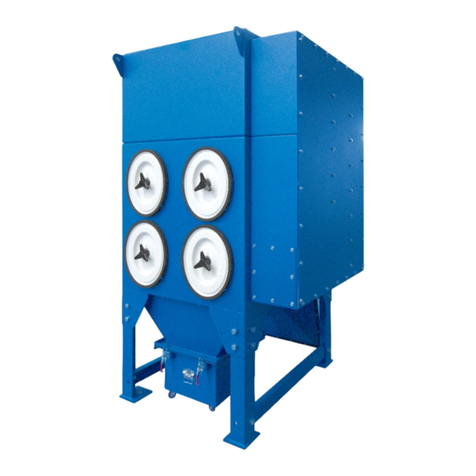
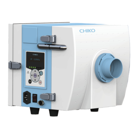
Donaldson DFPRE 6L Series User manual

DFPRE™ Dust Collectors
Series DFPRE 6L
INSTALLATION, OPERATION AND
MAINTENANCE MANUAL
Publication DOCAM1216501 (GB) 0720 MASTER LANGUAGE - ENGLISH

Installation, Operation and Maintenance manual
2
DFPRE 6L Dust Collectors

Installation, Operation and Maintenance manual
3
DFPRE 6L Dust Collectors
TABLE OF CONTENTS
IMPORTANT ................................................................................................................................. 4
Applications having a risk of sparks and fires...................................................................... 4
GENERAL SAFETY REQUIREMENTS........................................................................................... 5
INSTALLATION ............................................................................................................................. 8
Required tools and equipment ............................................................................................ 8
Delivery and inspection ....................................................................................................... 8
Location considerations....................................................................................................... 8
General guidance to lifting................................................................................................... 9
Positioning the collector .....................................................................................................10
Fan box assembly...............................................................................................................11
Dust container assemblies .................................................................................................12
Compressed air requirements............................................................................................12
Controller............................................................................................................................13
Overload protection ............................................................................................................13
Installation check list ..........................................................................................................13
COMMISSIONING.......................................................................................................................14
Commissioning check list...................................................................................................14
Start-up sequence ..............................................................................................................15
Shut-down sequence .........................................................................................................15
OPERATION ................................................................................................................................16
Principle of operation..........................................................................................................16
Dust disposal......................................................................................................................17
MAINTENANCE...........................................................................................................................18
Routine inspection..............................................................................................................19
Servicing schedule .............................................................................................................19
Valve disassembly/reassembly.......................................................................................... 21
Filter cartridge replacement .............................................................................................. 22
Fan assembly removal....................................................................................................... 24
Dismantle / decomission dust collector ............................................................................ 24
SPECIFICATION.......................................................................................................................... 28
SPARE PARTS LIST .................................................................................................................... 30
DECLARATION OF CONFORMITY............................................................................................. A1

Installation, Operation and Maintenance manual
4
DFPRE 6L Dust Collectors
IMPORTANT
Please read this manual carefully before installation.
This manual should be read in conjunction with the respective controller manual
supplied with the dust collector.
Product reliability, warranty and safe operation may be compromised by not following
the guidance given in these documents.
Applications having a risk of sparks and fires
1. Use
The DFPRE dust collector is designed for indoor/outdoor use, laser cut applications
and for handling non-explosive dusts.
2. EU Directive 99/92/EC
A reinforced and/or vented dust collector must be used when handling dusts
that have the potential to form an explosive atmosphere. If a non-reinforced and/
or non vented dust collected is used on these applications then the end user
must ensure an equivalent, secure, and fool proof basis of safety, which must
be clearly documented in the end users Explosion Protection Document in line
with Article 8 of EU Directive 99/92/EC.
3. Self Heating Materials
Please note that some materials have the potential to self generate heat and
hence to become an ignition source, that could result in a fire and / or an explosion
(exothermic reactions). For this reason, ferrous and non-ferrous materials should
not be extracted in to the same dust collector, as when combined they can create
a violent thermite reaction that would ignite a fire and/or explosion.
4. Applications having a risk of sparks and fires
Where sparks are generated by the process, this must be considered as a potential
ignition source which increases the risk of a fire or explosion. The filter can be
supplied with an optional spark trap to help reduce the frequency of spark ignition
and should be regarded as part of a risk reducing strategy.
The spark trap is not an extinguishment system and should never be relied upon
to achieve spark eradication in processes where suppression requirements are
absolute. The spark trap does not guarantee complete elimination of sparks
and does not preclude the possibility of fire or explosion. Therefore, system
redundancy and complementary measures should be taken in conjunction with
the spark trap to further reduce the risk of fire and explosion from sparks in
applications where there is potential for catastrophic combustion. Flame retardant
media is recommended for these type of applications.
On these types of applications the enduser should carry out regular good
housekeeping, such as:
• Periodically check for dust fall out in ducting and remove.
• Pulse down off line regularly to minimise retention of dust cake on filter
cartridges.
• Empty dust bins frequently.
Other risk reducing strategies could include:
• Inject with an inert material.
• Consider additional spark detection and fire suppression equipment.

Installation, Operation and Maintenance manual
5
DFPRE 6L Dust Collectors
GENERAL SAFETY REQUIREMENTS
The collector should be stored as supplied. Only remove packaging to install.
For the purposes of storage:
•
Collector with specification for inside use = IP50.
•
Collector with specification for outside use = IP54.
The dust collector has been built in accordance with state-of-the-art standards
and recognised safety rules. Nevertheless if not handled carefully it may put
people at risk and also cause damage.
The dust collector should be used only when it is in a technically acceptable
condition. Regular maintenance, as set out in this manual, is required to
minimise technical failure. Third party supplied components (for example
motors) should be maintained according to the manufacturer’s instructions.
You should ensure any persons carrying out work on the supplied equipment
follow any relevant recognised standards/codes, have received adequate
training and are competent to do so. Areas requiring a competent person
include:
•
Maintenance on any component identified as a potential ignition source.
•
Lifting and erection.
•
Electrical installation, inspection and maintenance work.
•
Pneumatic installation, inspection and maintenance work.
•
Any access to internal classified potentially explosive atmospheres where
there may be a risk due to explosion.
During assembly/installation or dismantling of equipment, potential ignition
sources may occur that were not considered in the risk assessment of the
unit in operation (for example, grinding, welding sparks, etc.)
You should use the dust collector in full accordance with the conditions set
out in the Order Acknowledgment and relevant Scope of Delivery. Failure to
do so may compromise product reliability, warranty and safety. The Scope of
Delivery is an integral part of the manual.
Other items of equipment, not supplied under the Scope of Delivery from
Donaldson, should be installed, operated and maintained according to the
documentation supplied with the respective equipment.
Any modification carried out on the ‘as supplied’ equipment may reduce
reliability and safety, and will nullify warranty; such actions fall outside the
responsibility of the original supplier.
The hopper should not be used as a storage vessel. To prevent damage to
the collector, care should be taken to avoid an excessive build up of heavy
materials.
Where necessary for safety, the dust collector is fitted with safety guards.
Removal of these guards and any subsequent work should only be carried
out after adequate precaution is taken to ensure it is safe to do so. All guards
should be refitted before re-energising.

Installation, Operation and Maintenance manual
6
DFPRE 6L Dust Collectors
The access door requires tools to open. To avoid danger from rotating fan
impellor, ensure fan is isolated and allow sufficient time for fan to become
stationary.
Do not put lit cigarettes or any burning object into the hood or ducting of any
dust collection system.
Compressed air is recommended for collectors that operate using reverse
jet cleaning. Alternative gases should be assessed before use to ensure that
explosive atmospheres are not introduced during media cleaning.
Care should be taken to ensure that any potentially explosive atmosphere
is not present when performing operations that increase the risk of ignition
(opening of controller for adjustment or electrical repair for example). Ensure
the installation is always returned to its original state.
All electrical equipment should comply with a category according to EN 60079-0.
The DFPRE dust collector is designed for handling non-explosive dusts.
Where applicable, equipment connected to the dust collector (for example,
a cyclone) should be protected, using suitable isolation devices, against the
transfer of flame and pressure if, in the event of an explosion initiating inside the
dust collector, the connected equipment is not capable of safely withstanding
these effects.
None of the fan assemblies can be considered to be a fully sealed design,
indeed most are arranged with either an open inlet or an open outlet. For this
reason, the internal and external atmospheres can be considered the same
in terms of any potentially hazardous classification.
Standard fan assemblies should not exceed 3000 rpm (50 Hz supply) on
systems fitted with an inverter drive.
The filtration media is suitable for filtering particulate only (and not gas).
Some applications are prone to risk of fire. This risk can be reduced by pulse
cleaning and emptying the dust container regularly.
•
Any extinguishing technique and material used must be suitable for the
flammable nature of the dust.
•
A water sprinkler system can be fitted as a special option.
Materials handled by the dust collector may be hazardous (e.g. toxic). Conduct
a Risk Assessment to ensure correct technique is employed.

Installation, Operation and Maintenance manual
7
DFPRE 6L Dust Collectors
Quick release
dust disposal
system
Clean air plenum
access door
Fan box
Lifting lugs for fan
box
Lifting bracket for
unit
Dirty air plenum
access door
Dirty air inlet
Hopper
Powerbox
Fork lifting profiles
Figure 1: DFPRE dust collector. Model DFPRE 6L Standard illustrated

Installation, Operation and Maintenance manual
8
DFPRE 6L Dust Collectors
INSTALLATION
The collector is not designed to support site-installed ducts, interconnecting
piping or electrical services. All ducts, piping or electrical services must be
adequately supported.
All external equipment connected to the dust collector (e.g. ducting) should
be correctly sealed. This can be achieved by applying a continuous 5 mm
bead of sealing compound to the mounting surface, along each side of the
hole pattern. For non-Donaldson equipment please also check supplier’s IOM
manual for any specific requirements.
Consider to place a back draft damper on outlet in order to prevent dust
migration during offline cleaning.
Required tools and equipment
• Crane/fork lift
• Slings/clevis pins and adequate lifting equipment
• Standard tools (e.g. screwdrivers, wrenches etc.)
• Drill
• Sealant
Delivery and inspection
The collector is normally supplied in one piece. Depending on your order, the following
parts are shipped loose:
• Dust disposal system
• Support structure
• Transition pieces
• Fan set (if not pre-mounted)
• Silencer
• Spare parts
• Anchor bolts
• Hardware and sealant
• Paint can and brush
Compare the parts received against the packing list. If there is any damage or parts
missing, notify the delivery company and your local Donaldson representative.
Location considerations
Where equipment is installed in a Potentially Explosive Atmosphere, care
should be taken not to locate or use the collector where external ignition
sources can be introduced, for example stray electric currents, lightening,
electromagnetic waves, ionising radiation, ultrasonic waves.
The collector should be located with consideration for:
• Emptying the dust container.
• Shortest runs of inlet and outlet ductwork with radius bends on elbows as large
as possible.

Installation, Operation and Maintenance manual
9
DFPRE 6L Dust Collectors
• Easy access to electrical and compressed air connections.
• Convenience of maintenance.
When calculating for foundations or support structure consider the following:
• The weight of the dust collector.
• The material being collected.
• All auxiliary equipment.
• Live loads.
• Snow and wind loads on outside installations.
For collector weights and dimensions refer to the datasheet, publication number
DOCAM1216301
General guidance to lifting
The collector should be lifted using either the four-point lifting arrangement or
the fork-lifting arrangement by a qualified competent person (refer to figures
2 and 3).
During all lifting operations a crane or fork lift with an adequate SWL (safe
working load) must be used. (Refer to lifting label located adjacent to lifting
points for weight of equipment supplied by Donaldson).
When using the four-point lifting method, chains or slings with an adequate
SWL (safe working load) must be used. (Refer to lifting label located adjacent
to lifting points for weight of equipment supplied by Donaldson). Chains must
be long enough to ensure that the included angle between diagonal chains is
not greater than 90° (refer to figure 2, 3 and 4)).
Care should be taken as the unit might have a high center of gravity.
Do not use the lifting lugs of the spark trap / cyclopeel.
Before unloading, remove all packing and strapping.
≤ 90°
≥ 1.2 m
Figure 2: Four-point lifting arrangement Figure 3: Fork lifting arrangement

Installation, Operation and Maintenance manual
10
DFPRE 6L Dust Collectors
Figure 4: Lifting
Positioning the collector
1. Lift the collector into position following the general guidance to lifting.
Take care not to damage dust container and cables when using fork lifting
method.
2. Using spirit levels, line up both horizontally and vertically, using shims where
required.
3. Where applicable, secure the collector to the foundation anchor bolts.
Do not use the lifting lugs of the fan box when the unit is equipped with a fan
box.consider
The lifting profile can be removed after securing the collector, see figure 5.
Store the profiles for eventual future use.

Installation, Operation and Maintenance manual
11
DFPRE 6L Dust Collectors
Figure 5: Removal lifting profiles
Fan box assembly
For collectors supplied with a fan box:
Refer also to figure 4.
The outlet position can be changed from the side to othe rear by swapping
the grill and cover before mounting the fan box.
1. Apply a continuous 5 mm bead of sealing compound to mounting surface of
collector, along each side of hole pattern.
2. Using a four-pount lifting arrangement, lift fan box into position and align bolt holes.
3. Bolt fan to the collector
Figure 6: Fan box assembly

Installation, Operation and Maintenance manual
12
DFPRE 6L Dust Collectors
Dust container assemblies
1. Apply a continuous 5 mm bead of sealing compound to mounting surface of dust
container, along eacht side of the bolt pattern.
2. Bolt dust container to the hopper flange.
The dust container can be moubted to operate from the front, rear or
either side.
hopper
sealant
quick release
dust bin
80 L dust drum
hook on
dust bin
200 L dust drum
M10 nut
M10 washer
Figure 7: Dust container assembly
Compressed air requirements
DFPRE dust collectors require an independent supply of clean, dry, oil-free
compressed air. Details of pressure and quantity requirements are given in Table 3
(refer to ‘Specification’ section). A design label is also attached to each manifold.
Where an existing factory mains system is to be used it may be necessary to install
an additional moisture separator in the supply line to the collector. If a compressor
is being installed to supply the collector, then the following conditions should be
observed as far as possible:
Type of compressor
Use a compressor of ample capacity – an overloaded compressor may produce
excessively contaminated, moisture-laden air.
Location of air intake
Avoid locating the air intake in an excessively polluted area and install an adequate air
intake filter. The compressor air intake should be sited, if possible, on the north side
of the building – fresh air drawn from the north side is usually cooler and denser, and
therefore has a lower moisture content. (South of the equator the reverse will apply).
Layout and installation of air lines
The pipework between compressor and dust collector should be long enough to
act as a cooling device for the compressed air. A typical requirement for the smaller
installation would be 10 m (30ft) of 12 mm (½” NB) piping. For further details seeTable
3. The piping should be installed to provide a fall in the direction of air flow to assist
in the drainage of accumulated moisture. A moisture separator should be provided
at the lowest point of the installation.

Installation, Operation and Maintenance manual
13
DFPRE 6L Dust Collectors
Pressure relief
The manifold has a maximum design pressure of 8 bar (seeTable 2 in ‘Specifications’
section). It is a requirement that adequate protection is made not to exceed this
pressure.
We advise to install a pressure regulator - oil/water separator to regulate
the compressed air and to ensure the compressed air is free from oil and
condensate.
Controller
It is a requirement of the Supply of Machinery (Safety) Regulations 2008 to
provide adequate isolation and emergency stop facilities. Due to the varied
nature of site installations this cannot be provided by Donaldson but instead
is the responsibility of the customer.
Always isolate power before opening the controller.
Each DFPRE dust collector is supplied with a factory fitted Powerbox to operate the
fan and the compressed air cleaning system.
For controller connections and set-up, refer to the controller manual.
Details of standard fan motor supply voltage are given in Table 4 (refer to
‘Specification’ section).
Overload protection
All feeder circuits should be adequately protected with suitably-rated fuses and
contactors with integral overload protection.
Installation check list
Where applicable, ensure that the collector is securely bolted to the floor.
Ensure compressed air supply is free from leaks, installed correctly and
according to the compressed air specifications, Table 2 and 3.
Ensure electrical supply is installed correctly and complies to local legislation.
Ensure all the electrical components are complying with the zone where they
are installed.

Installation, Operation and Maintenance manual
14
DFPRE 6L Dust Collectors
COMMISSIONING
It is a requirement of the Supply of Machinery (Safety) Regulations 2008 to
provide adequate isolation and emergency stop facilities. Due to the varied
nature of site installations this cannot be provided by Donaldson but instead
is the responsibility of the customer.
Before putting the dust collector into service the following items should be checked.
Similar checks, as appropriate, should be made after any major overhaul.
Commissioning check list
Where applicable, ensure that the collector is securely bolted to the floor.
Ensure dust disposal system is correctly installed.
Ensure all ducting is complete, all detachable panels are in position and fixed
guards are secure.
When new filter elements are installed it is necessary to reduce the airflow
through the filter media by partially closing the slide gate.
This way the dust will not penetrate the media and can be cleaned off as
described above. After the elements are conditioned the slide gate can be
placed back to its original position.
Ensure collectors are suitably earthed.
Ensure electrical power is available.
Check fan motor for correct rotation and that the full load current is not exceeded.
(Refer to the fan rotation label located on the fan mounting plate inside the
clean air chamber).
Keep clear of inlet opening/rotating impeller whilst performing rotation
check.
To reverse rotation (single phase power supply):
Follow manufacturer’s instructions on the motor nameplate.
To reverse rotation (three phase power supply):
Turn electrical power OFF at source and switch any two phase wires on either
the motor junction box or the controller input terminals.
Ensure access panel seals are intact, then close and secure the panels.
Ensure the compressed air manifold has sufficient protection for overpressure.
Start the compressor and check that the air supply is maintained at the
recommended pressure.
Switch on the controller.
When Delta P cleaning is selected, then the cleaning system will not
operate until the differential pressure rises above a set value of 80 daPa.
If any of the above check boxes are not ticked, then the reasons why should be
investigated. (Refer to fault location table in ‘Maintenance’ section).

Installation, Operation and Maintenance manual
15
DFPRE 6L Dust Collectors
Start-up sequence
1. Turn on compressed air supply.
2. Check that the compressed air supply is maintained at the recommended
pressure.
3. Adjust the damper valve as described in commissioning.
4. Switch on controller.
Shut-down sequence
At the end of any period of operation it is most important that all residual
deposits are cleared from the filter cartridges, casing, and discharge hopper.
To achieve this, equipment should be shut down in the following order:
1. Stop fan only, leaving controller and compressed air supply switched on to allow
filter to be cleaned ‘off-line’.
To enable off-line cleaning, see controller manual.
2. After 10-15 minutes, switch off controller and the compressed air.
Where the dust being handled has self-heating properties, it is important to
remove any deposits in the dust container to reduce the risk of an explosion.
Adherence to the above procedure will ensure that the dust collector installation is
maintained at optimum efficiency.

Installation, Operation and Maintenance manual
16
DFPRE 6L Dust Collectors
OPERATION
On installations where the inlet duct is relatively short, this procedure may
result in a dust emission occurring at the inlet and therefore may not be an
appropriate procedure if the dust being handled is dangerous.Therefore a Risk
Assessment must be carried out to ensure the final procedure is safe.
Principle of operation
(Refer also to figure 4).
Contaminated air from the dust generation source is drawn through the inlet to the
collector by the fan. Airflow is directed through the collector and heavier particulate
falls directly into the hopper. The cartridges remove the fine particulate and clean,
filtered air passes through the cartridge to the clean air chamber and discharges
through the clean air outlet.
At regular intervals, governed by the controller, each cartridge in turn receives a short
burst of compressed air from an adjacent air diaphragm valve. These valves are at an
optimum distance from the cartridge, ensuring that a large volume of air is induced
by each injection of compressed air, causing a brief, powerful reversal of airflow
through the cartridge, effectively dislodging the dust layer which then falls into the
discharge hopper.
b Cleaning operation (intermittent)
(Each cartridge is cleaned separately, in turn)
a Filtering operation (continuous)
Hopper
Dust container
Cleaned air
outlet
Contaminated
air inlet
Cartridge
Compressed
air manifold
Diaphragm valve
Figure 8: Principle of operation

Installation, Operation and Maintenance manual
17
DFPRE 6L Dust Collectors
Dust disposal
For safe handling of the dust container an assessment must be made to satisfy
the requirements of the European Directive 90/269/EEC on manual handling
of loads.
Dust containers may require regular emptying.
Dust containers should securely replaced and resealed prior to collector restart.
This is a good time to check the dust container for damage, which may lead
to a dust leak or flame emission in the rare instance of an internal explosion.
Turn off the dust collector and empty the dust container on a regular basis using one
of the following procedures:
Empty the dust container when ¾ full.
Quick release dust bin (collector hopper and cyclopeel)
1. Release the container by lowering the handle
2. Remove and empty the container
3. Replace container by sliding it back into position
4. Reseal the container by raising the handle.
Hook on dust bin (collector hopper and cyclopeel)
1. Release the container by unclamping both latches
2. Remove and empty the container
3. Replace container by sliding it back into position
4. Reseal the container by clamping down both latches.
80 L drum (for collector (collector hopper only)
1. Close the butterfly valve
2. Open clamp and lift dust bin cover
3. Replace dust bin, position cover and tighten clamp
4. Open buttefly valve
Ensure the butterfly valve is opened before restating the collector.
200 L drum (collector hopper only)
1. Close the butterfly valve
2. Open clamp and lift dust bin cover
3. Replace dust bin, position cover and tighten clamp
4. Open buttefly valve
Ensure the butterfly valve is opened before restating the collector.

Installation, Operation and Maintenance manual
18
DFPRE 6L Dust Collectors
MAINTENANCE
A platform should be used when carrying out maintenance where the position
of the technician’s feet is greater or equal to 2 metres above ground level.
Before any work is carried out, ensure the equipment is adequately isolated
and safe.
Ensure the pneumatic system is fully isolated and depressurised before any
work is carried out.
For ancillary equipment not manufactured by Donaldson, refer to manufacturer’s
instructions.
If it is unavoidable to work on the equipment while a potentially explosive
atmosphere is present, care should be taken to avoid introducing ignition
sources not present during expected operation. Non-sparking tools should be
used.
Access to the Dirty Air Plenum of the equipment may create risks and hazards
that under normal circumstances are not present and as such this work must
be carried out by competent personnel. These risks include inhalation of dust
and potential explosion hazards. Appropriate personal protection equipment
(PPE) should be used, e.g. dust mask, safety hat, gloves etc.
In order to maintain the original collector specification and to ensure the same
level of safety, only genuine spare parts should be fitted.
Every care has been taken to avoid the risk of ignition of a flammable
atmosphere.The measures taken to avoid ignition should not be altered since
this may result in unsafe operation. Particular care should be taken during
maintenance and component replacement to ensure the same level of safety
is maintained.When replacing fan impellers, avoid any rubbing of components
(to prevent mechanical sparks).
Care should be taken during cleaning and maintenance to avoid creating static
discharges that have the potential to ignite a flammable atmosphere.
When carrying out maintenance always follow typical best practice to local
regulations (e.g. TRGS 560).

Installation, Operation and Maintenance manual
19
DFPRE 6L Dust Collectors
Routine inspection
To maintain the optimum performance of the dust collector, a routine inspection should
be made to minimise down-time in the event of equipment malfunction, particularly
on continuous performance applications and to ensure the equipment is maintained
to its original supply condition.
Any abnormal change in differential pressure across the filter cartridges indicates a
change in operating conditions and a fault to be rectified. For example, a prolonged
stoppage of compressed air will cause an excessive build-up of dust on the cartridges,
resulting in a greatly increased pressure drop.
After the fault has been rectified, resumption of compressed air cleaning will usually
return the filter to normal efficiency. However, it is advisable to operate the in still-air
conditions for a short period to dislodge any accumulated dust before putting the
collector into operation.
Filter resistance can be checked by viewing the display on the front panel of the
controller.This will give a continuous indication of the state of the filter. Once running,
the operating resistance will be relatively stable, the actual value depending on the
air volume and the characteristics of the dust being handled.
If the differential pressure exceeds 120 mm WG, check the following:
•
The compressed air supply is installed correctly, is free of water or oil and
is maintained at the recommended pressure (refer to Table 3).
•
The differential pressure connections are not blocked.
•
The solenoid and diaphragm valves are functioning correctly.
•
The controller is operational.
•
The dust container is properly sealed.
If the differential pressure still exceeds 120 mm WG after checking the above,
then reduce the pulse cleaning interval time to see if this will improve the
cleaning of the filter cartridges and, in turn, lower the differential pressure
(details of pulse interval settings are provided in the controller manual).
If the differential pressure exceeds 150 mm WG, then the cartridges have
reached the end of their lifetime and need replacing.
Ignition minimising fans are fitted with a lining inside the casing. As this may
only offer protection for a limited period, if there is any upset condition leading
to rubbing, then the fan must be switched off immediately and the condition
corrected.
It is recommended to periodically inspect the general casing integrity.
Do not operate above recommended compressed air pressure. Excessive
pressure will reduce the working life of components.
Servicing schedule
A record of all pressure checks should be kept in a log book to aid the speedy diagnosis
of faulty operation.
Daily
1. Check level of contents in dust container and cyclopeel if applicable, and empty
if ¾ full.

Installation, Operation and Maintenance manual
20
DFPRE 6L Dust Collectors
Weekly
1. Open valve at the bottom of moisture separator bowl and allow collected water
to drain off, then close valve.
2. Check the pressure drop across the filter by viewing the display on the front
panel of the controller. If excessive, refer to Table 1.
Every 2 weeks
1. Check for visible effluent from cleaned air outlet. If evident, refer to Table 1.
2. Check controller settings (refer to controller manual).
3. For units fitted with a sparktrap, open sparktrap inspection cover and check for
dust deposit. Clean dust to avoid fire ignition. Close inspection cover.
Monthly
1. Check dust seals on all access panels for damage or ageing and ensure they are
properly seated to prevent entry of water. This is particularly important where
the collector is located outside or in a wet atmosphere.
Faulty seals must be replaced.
2. Check operation of solenoid and diaphragm valves. If it is found necessary to
replace a diaphragm, refer to Valve disassembly/reassembly.
It may be necessary to check operation of the valves while the system is
pressurised. Care should be taken to avoid injury.
Every 2 months
1. Check connected ducting. Repair any leaks as necessary.
Every 6 months
1. Check general casing integrity and support structure. Repair or replace as
necessary.
2. The fan impellor has been dynamically balanced and the fan assembly vibration
level should be in line with category BV-3, ISO 14694. An assessment of vibration
should be made every six months, or after a significant emission, or after any
misuse and a record kept of measured values. Excessive vibration levels should
be investigated and corrected immediately.
Vibration monitoring is mandatory on category 2G, 3G and 2D fan
assemblies.
Annually
1. Remove and clean moisture separator filter element.
2. Remove drain plug and air inlet connections from compressed air manifold. Clean
out any accumulated sludge and inspect to any current local legislation.
It may be necessary to remove a diaphragm valve for internal inspection
purposes.
3. If applicable, check all flameproof enclosures, motors and cable glands for
corrosion and tightness.
This manual suits for next models
1
Table of contents
Other Donaldson Dust Collector manuals

Donaldson
Donaldson DFPRE 4L User manual

Donaldson
Donaldson DFOI4 User manual

Donaldson
Donaldson DCE HV500 Series User manual

Donaldson
Donaldson TDS User manual

Donaldson
Donaldson DFPRE 4 Series User manual

Donaldson
Donaldson DFOE3 User manual

Donaldson
Donaldson DLM V Series User manual

Donaldson
Donaldson PowerCore CPV Series User manual

Donaldson
Donaldson Torit RF Series User manual

Donaldson
Donaldson HV150 User manual