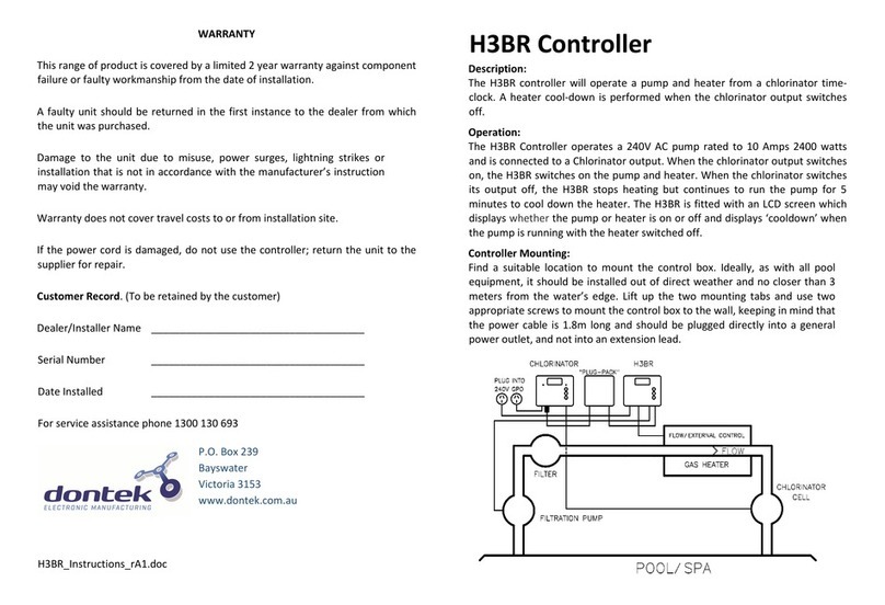
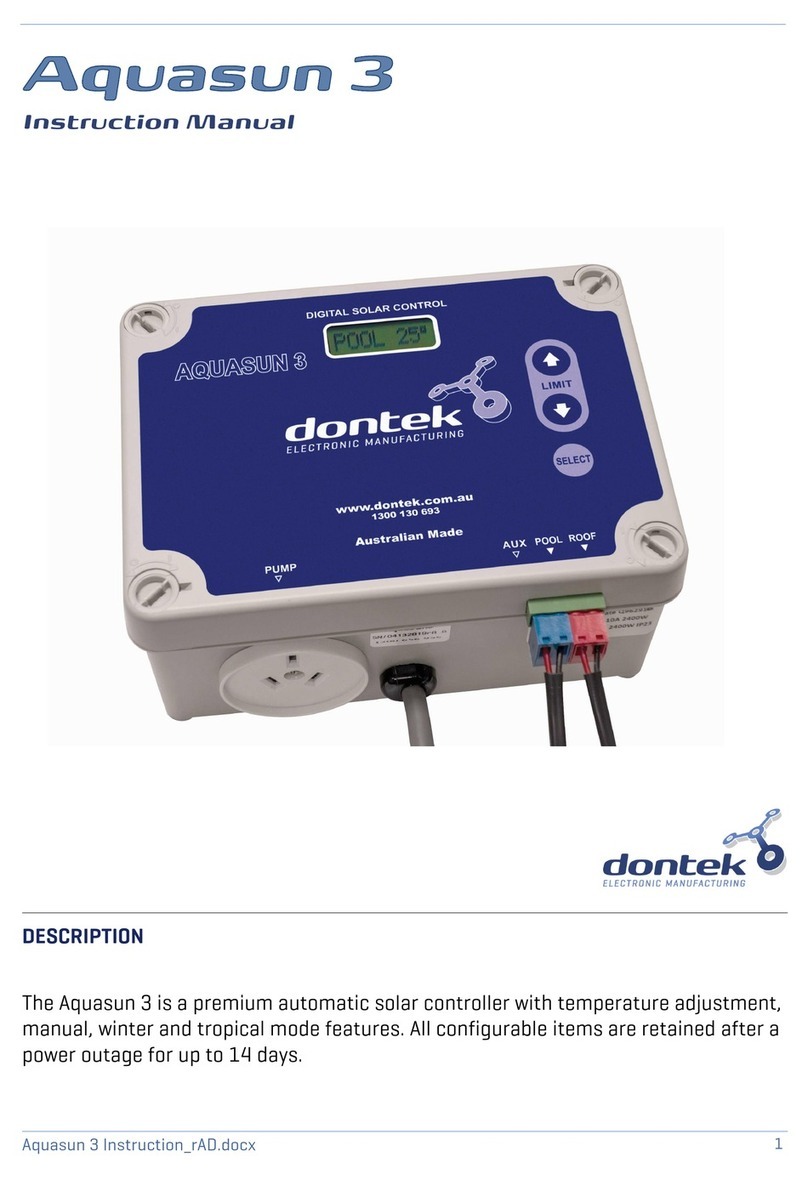
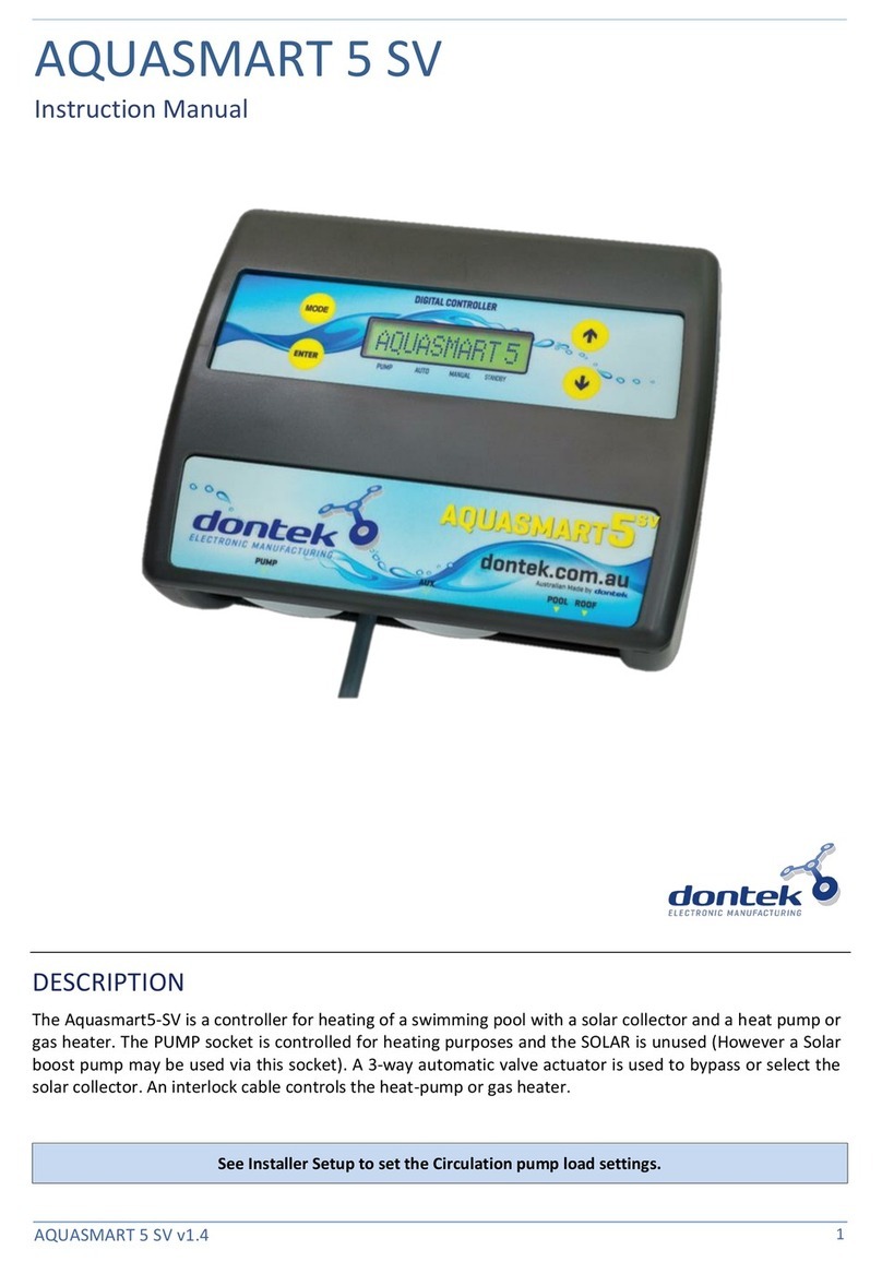
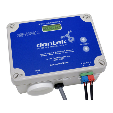
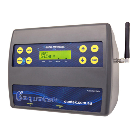
Dontek AQUAHEAT H5TC User manual

AQUAHEAT H5TC v1.0
1
AQUAHEAT H5TC
Instruction Manual
DESCRIPTION
The H5TC Controller is designed to switch a 2 0Vac pump and control a heater via a relay contact rated to
5A @ 2 Vac. This unit is designed to be connected to a Chlorinator output via a secondary power lead
(Black). When the chlorinator output is turned on, the H5TC switches on the pump and
the heater is turned
on. This is dependent on the heating times and temperature limits as set on the H5TC.
When the chlorinator turns off, the H5TC
continues to operate to meet its own heating times &
temperature limits. If the temperature limit is reached or if outside of heating times
, the heater is
switched off. A heater cool-down continues to operate the pump for an adjustable period and
if the
chlorinator is not currently active, the unit will stop the pump and start an adjustable sample wait period.
The
H5TC
is fitted with an LCD screen which displays
whether
the pump or heater is on or off, when it

AQUAHEAT H5TC v1.0
2
Fix the mounting bracket to a solid structure
via screws and wall plugs kit provided, and
slide the controller on, locking into place.
Adjusting screws on the back of unit to ensure
snug fit
To remove unit, lift and gently pull away from
structure.
INSTALLATION INSTRUCTIONS
THIS APPLIANCE IS NOT INTENDED FOR USE BY
YOUNG CHILDREN OR INFIRM PERSONS WITHOUT
SUPERVISION. PLEASE ENSURE THAT YOUNG
CHILDREN ARE SUPERVISED TO ENSURE THAT
THEY DO NOT PLAY WITH THE APPLIANCE.
CONTROLLER MOUNTING
Find a suitable location to mount the control box.
Ideally, as with all pool equipment, it should be
installed out of direct weather and no closer than
3 metres from the water’s edge and a minimum
600mm above ground. The power cable is 1.8m
long and should be plugged directly into a
general power outlet, not into an extension lead.
PUMP CONNECTIONS
The pool circulating pump plugs into the 2 0V
socket labelled PUMP.
SANITISER CONNECTION
The sanitiser (Ioniser, Chlorinator or Ozoniser
etc.) connects directly into a general power
outlet, not into an extension lead. Plug the Black
power lead from H5TC into the sanitiser. Set the
sanitiser to operate for the required filtration and
dosing requirements.
POOL SENSOR
The pool sensor must be fitted into the heating
circuit, as close to the pool as practical,
preferably in a position out of direct sunlight. It is
recommended that a 1 .5mm hole be drilled into
the side of the PVC pipe (not the top of the pipe
where water will collect). This can be carried out
using a Dontek PD01 grinding drill or a small pilot
hole can be drilled with a 1 .0mm drill-bit used
spinning in a counter clockwise direction to
minimize the chance of shattering pipe. Insert
the grommet into the pipe and gently push in the
sensor barb. Ideally ~30cm of the cable from the
sensor should be tied to the shaded side of the
pipe to prevent extreme ambient conditions
leeching into the sensor via the copper in the
cable. The blue sensor plug is to be fitted to the
plug socket marked POOL.
HEATER:
Connect the heater cable from the controller
output marked HEATER to the heaters flow or
pressure switch. Check with heater manufacturer
for correct interlocking procedure. See picture
for typical connection set-up. Note damage
caused by incorrect connections will void
warranties.
Internal connection to pool heater (check with
heater manufacturer).

AQUAHEAT H5TC v1.0
3
OPERATING INSTRUCTIONS
LCD SCREEN
In automatic mode, the LCD screen displays the
pool and roof temperatures, solar temperature
limit, on/off/locked-out status and the time of
day & date (clock). In manual heating mode the
controller displays the temperature and set
temperature.
LCD INDICATORS
There are arrow icons on the LCD screen that
point to text on the label.
MODE BUTTON
Three options are available, heating, 1
st
heat and
standby.
HEATING MODE (AUTO)
performs heating during
the runtime.
1ST HEAT
will ignore the run timer (RUNHRS) to
run the pool until the desired temperature limit is
achieved. Once the temperature limit is reached
the controller revert back to heating mode to
only run the heating during the set run times
(RUNHRS).
STANDBY
does not perform heating but a three
minute maintenance flush occurs every day at
noon (12:00).
COOLING
use with heat pumps that have a cooling
function performs cooling during the runtime.
↑ AND ↓ BUTTONS (TEMPERATURE SETTING)
To change the pool or spa temperature limit
simply press the UP button to increase and the
DOWN button will decrease.
ENTER BUTTON
Pressing the ENTER button will turn on the LCD
backlight, pressing the ENTER button while the
backlight is lit will enter the SETTINGS MENU;
The following will be displayed; 1) EXIT, The menu
system can be navigated using the ↑ or ↓
buttons, all selectable and changeable values will
flash on the LCD screen. Press the ENTER button
to accept the currently displayed (flashing) item.
All menu items are shown below;
1) EXIT
2) CLOCK
3) RUNHRS
4) SYSTEM
1) EXIT
Press ENTER on this menu to return to automatic
operation.
2) CLOCK
When selecting the clock, you will have to set the
time of day
3) RUNHRS
When selecting this menu, you are prompted to
set the number of automatic heating cycles per
day to run, CYCLES OFF to 2.
If OFF is selected (no automatic heating) then
the following menus are skipped.
If 1 or 2 heating cycles per day is selected, you
will be prompted to set the start & end time(s);
the heater (with pump) will only be allowed to run
between these hours. Set the start time (S1
hh:mm) and end time (E1 hh:mm) in half hour
steps (30 mins), repeat if a 2nd cycle is selected.
4) SYSTEM
Here is a sub-menu;
EXIT
SAMPLE
INSTALL
LCD TIME
DEFAULTS
EXIT - Press ENTER on this menu to return to
automatic operation.
SAMPLE Temperature limit sample time (S xx
MIN), this stops the pump for the selected time
period once the temperature limit has been
achieved *⁷
INSTALL;
CAL – Calibrate the TS02P sensor.
SET HEATER COOL- DOWN - When the heater
switches off the pump is locked to run for a time
period without heating, this is to cool down the
heater and prevent damage to the heater (and
pipes) from heat soak.
Set run-on time (R XX MIN) is adjustable from
HP, 1 to 30 minutes. (HP is For Heat Pump that
require no cool down)
LCD TIME – Adjust the number of seconds the
backlight remains on after the time a button was
pressed. (Select NONE for always on.)
DEFAULT – Returns all setting the factory
defaults.
AQUAHEAT H5TC v1.0
NOTES:
1. If any of the menu items are left unattended
for 3 minutes, the menu will time out and
automatically save all settings and return to
automatic operation.
2. If a sensor fault is detected the controller will
display which sensor and what the fault is.
3. Should power be interrupted for any reason,
the controller will resume normal operation
when power is restored, all information will
have been kept for 10 days.
. If the controller has stopped pumping and is
displaying a higher temperature than
expected it may be caused by a pump which
is failing to prime, check the pump and if
necessary prime the pump as per the pump
manufacturers’ instructions then reset the
controller by turning it off/on.
5. Maximum combined rated output load for the
2 0V socket(s) is 9.98 Amps / 2395 Watts.
6. Degree of protection against moisture: IP33.
7. Smaller bodies of water running a higher
temperature limit (i.e. spa) the sample time
should be set shorter than larger bodies of
water that run lower temperature limits (i.e.
pool). If the pump runs for 3 minutes and
stops frequently, then increase the sample
time as the body of water is not losing much
heat.
8. On power-up there is a counter next to the
revision number that displays the number of
interrupted heater cool-down cycles. This
number cannot be reset.
9. A voltage free switch can be wired into the
righthand Red plug which will force heating
out of demand times.
WARRANTY
•This range of product is covered by a limited 3 year warranty against component failure or
faulty workmanship from the date of installation.
•Faulty units should be returned in the first instance to the dealer from which the unit was
purchased.
•Damage to the unit due to misuse, power surges, lightning strikes or installation that is not in
accordance with the manufacturer’s instruction may void the warranty.
•Warranty does not include on-site labour or travel costs to or from installation site.
If the power cord is damaged, do not use the controller; return the unit to the supplier for repair.
CUSTOMER RECORD
(To be retained by the customer)
DEALER/INSTALLER NAME
SERIAL NUMBER
DATE INSTALLED
For service assistance email service@dontek.com.au
Don ek Elec ronics P y L d
www.dontek.com.au
PO Box 239, Bayswater VIC 3153 Australia
Phone: +613 9762 8800 Email: sales@dontek.com.au
Other Dontek Controllers manuals

Dontek
Dontek V2 Series Service manual

Dontek
Dontek Aquasun 3 User manual

Dontek
Dontek V2-1 User manual

Dontek
Dontek Aquasun 3CD User manual

Dontek
Dontek H3BR User manual

Dontek
Dontek AQUATEK User manual

Dontek
Dontek V7-RTS User manual

Dontek
Dontek V7-1 STD User manual

Dontek
Dontek Aquasun 2 User manual

Dontek
Dontek Aquasmart 5 RP User manual