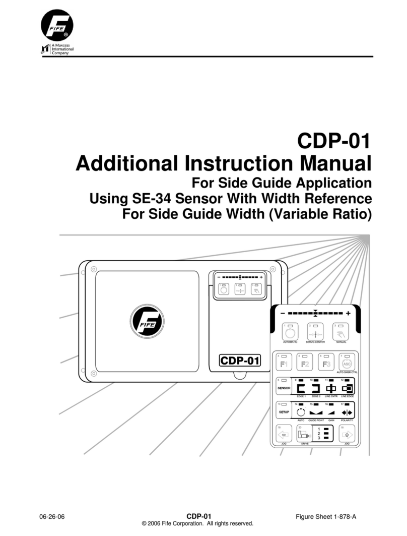
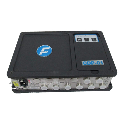
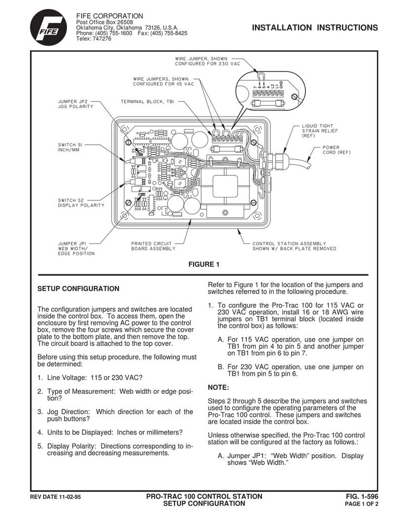
Fife CDP-01 User manual

05-21-04 CDP-01 Figure Sheet 1-876
CDP-01
Additional Instruction Manual
For Sensor Calibration Using SE-34 Sensor

05-21-04 CDP-01 Figure Sheet 1-876

SUPPLEMENTARY OPERATING MANUAL i
05-21-04 CDP-01 Figure Sheet 1-876
COPYRIGHT
NOTE
These additional instructions explain the special features of the system delivered to the customer. They
are intended for being used in conjunction with the CDP-01 Reference Manual. The CDP-01 Reference
Manual applies except as noted to the contrary in these instructions.
Copyright:
All rights reserved. Any reproduction of this Additional Instruction Manual, in any form, in whole or in part,
requires the prior written consent of FIFE.
The information given in this Additional Instruction Manual is subject to change without notice.
We have compiled this Additional Instruction Manual with the greatest possible care and attention:
however, the possibility of error can not be completely excluded. FIFE accepts no legal liability for
incorrect information given and the consequences arising therefrom.
Copyright 2004 FIFE Corporation, P.O. Box 26508, Oklahoma City, OK 73126, U.S.A.
FIFE GmbH,Postfach 1240, D-65762 Kelkheim/Ts., Germany

05-21-04 CDP-01 Figure Sheet 1-876

SUPPLEMENTARY OPERATING MANUAL iii
05-21-04 CDP-01 Figure Sheet 1-876
TABLE OF CONTENTS
GENERAL INTRODUCTION 1
APPLICATION DESCRIPTION..............................................................................................1-1
SOFTWARE PART NUMBERS.............................................................................................1-1
CONNECTING THE SYSTEM COMPONENTS....................................................................1-1
SENSOR CALIBRATION 2
STANDARD ’O’ FRAME SE-34 (FIRST EDGE)....................................................................2-1
STANDARD ’O’ FRAME SE-34 (SECOND EDGE)...............................................................2-2
’C’ FRAME SE-34 (FIRST EDGE) .........................................................................................2-3
’C’ FRAME SE-34 (SECOND EDGE)....................................................................................2-4
SPLIT SENSOR SE-34 (FIRST EDGE).................................................................................2-5
SPLIT SENSOR SE-34 (SECOND EDGE) ...........................................................................2-6

05-21-04 CDP-01 Figure Sheet 1-876

SUPPLEMENTARY OPERATING MANUAL 1
1-1
05-21-04 CDP-01 Figure Sheet 1-876
GENERAL INTRODUCTION
Application Description
Application is a Guide using the analog output of the SE-34 Sensor through X1 or X2. The sensor
signal is an analog signal that may need calibrating.
This procedure can also be applied to a Sensor connected to X3 with the following substitutions in
the Manual:
LED 9 ÆLED 11
LED 10 ÆLED 12
A CDP-01 is required for this application.
Software Part Numbers
The software part numbers are located on the side of the CDP-01 housing. They include the
Matrix Setup no. (MS), State Machine no. (SM) and firmware version ( Dx ).
CDP version: CDP-01 D1:5650xx-02x MS: xxxxxx-02x Please quote these
D2:5650xx-02x SM: xxxxxx-02x details with all inquiries.
D3:5650xx-02x FIFE USA
Connecting the System Components
The system components are to be connected according to the Cable Connection Diagram
contained in the documentation.

05-21-04 CDP-01 Figure Sheet 1-876

SUPPLEMENTARY OPERATING MANUAL 2
2-1
05-21-04 CDP-01 Figure Sheet 1-876
SENSOR CALIBRATION
Standard ‘O’ Frame SE-34 (First Edge)
The following procedure must be performed while in Manual mode with all parallel inputs low.
a.
Press the Sensor key repeatedly until LED 9 is lit.
b.
Press the Setup key.
Check: LED 3 flashes.
c.
Press the Sensor key.
Check: LED 8 & 9 lit.
d.
Remove web material fully from sensor proportional
band.
e.
Press the F1 key
Check: LED 4 lit.
f.
Bring web material fully into sensor proportional band.
g.
Press the F2 key.
Check: LED 4 & 5 lit.
h.
The LED bar graph indicates contrast. If the contrast is
too low an error message is displayed (left and right
outer LEDs flash).
j.
Press the Automatic key to store the settings.
or
k.
Press the Manual key to abort the procedure.

SUPPLEMENTARY OPERATING MANUAL 2
2-2
05-21-04 CDP-01 Figure Sheet 1-876
Standard ‘O’ Frame SE-34 (Second Edge)
The following procedure must be performed while in Manual mode with all parallel inputs low.
a.
Press the Sensor key repeatedly until LED 10 is lit.
b.
Press the Setup key.
Check: LED 3 flashes.
c.
Press the Sensor key.
Check: LED 8 & 10 lit.
d.
Remove web material fully from sensor proportional
band.
e.
Press the F1 key
Check: LED 4 lit.
f.
Bring web material fully into sensor proportional band.
g.
Press the F2 key.
Check: LED 4 & 5 lit.
h.
The LED bar graph indicates contrast. If the contrast is
too low an error message is displayed (left and right
outer LEDs flash).
j.
Press the Automatic key to store the settings.
or
k.
Press the Manual key to abort the procedure.

SUPPLEMENTARY OPERATING MANUAL 2
2-3
05-21-04 CDP-01 Figure Sheet 1-876
‘C’ Frame SE-34 (First Edge)
The following procedure must be performed while in Manual mode with all parallel inputs low.
a.
Press the Sensor key repeatedly until LED 9 is lit.
b.
Press the Setup key.
Check: LED 3 flashes.
c.
Press the Sensor key.
Check: LED 8 & 9 lit.
d.
Remove web material fully from sensor proportional
band.
e.
Press the F1 key
Check: LED 4 lit.
f.
Bring web material fully into sensor proportional band.
g.
Press the F2 key.
Check: LED 4 & 5 lit.
h.
The LED bar graph indicates contrast. If the contrast is
too low an error message is displayed (left and right
outer LEDs flash).
j.
Press the Automatic key to store the settings.
or
k.
Press the Manual key to abort the procedure.

SUPPLEMENTARY OPERATING MANUAL 2
2-4
05-21-04 CDP-01 Figure Sheet 1-876
‘C’ Frame SE-34 (Second Edge)
The following procedure must be performed while in Manual mode with all parallel inputs low.
a.
Press the Sensor key repeatedly until LED 10 is lit.
b.
Press the Setup key.
Check: LED 3 flashes.
c.
Press the Sensor key.
Check: LED 8 & 10 lit.
d.
Remove web material fully from sensor proportional
band.
e.
Press the F1 key
Check: LED 4 lit.
f.
Bring web material fully into sensor proportional band.
g.
Press the F2 key.
Check: LED 4 & 5 lit.
h.
The LED bar graph indicates contrast. If the contrast is
too low an error message is displayed (left and right
outer LEDs flash).
j.
Press the Automatic key to store the settings.
or
k.
Press the Manual key to abort the procedure.

SUPPLEMENTARY OPERATING MANUAL 2
2-5
05-21-04 CDP-01 Figure Sheet 1-876
Split Sensor SE-34 (First Edge)
The following procedure must be performed while in Manual mode with all parallel inputs low.
a.
Press the Sensor key repeatedly until LED 9 is lit.
b.
Press the Setup key.
Check: LED 3 flashes.
c.
Press the Sensor key.
Check: LED 8 & 9 lit.
d.
Remove web material fully from sensor proportional
band.
e.
Press the F1 key
Check: LED 4 lit.
f.
Determine active portion of the Sensor by waving a flag
in the sensor and watching the CDP-01 bargraph.
Bring web material into sensor and fully cover the active
portion of the sensor.
g.
Press the F2 key.
Check: LED 4 & 5 lit.
h.
The LED bar graph indicates contrast. If the contrast is
too low an error message is displayed (left and right
outer LEDs flash).
j.
Press the Automatic key to store the settings.
or
k.
Press the Manual key to abort the procedure.

SUPPLEMENTARY OPERATING MANUAL 2
2-6
05-21-04 CDP-01 Figure Sheet 1-876
Split Sensor SE-34 (Second Edge)
The following procedure must be performed while in Manual mode with all parallel inputs low.
a.
Press the Sensor key repeatedly until LED 10 is lit.
b.
Press the Setup key.
Check: LED 3 flashes.
c.
Press the Sensor key.
Check: LED 8 & 10 lit.
d.
Remove web material fully from sensor proportional
band.
e.
Press the F1 key
Check: LED 4 lit.
f.
Bring web material into sensor and fully cover the
opposite portion of the sensor from the previous step.
g.
Press the F2 key.
Check: LED 4 & 5 lit.
h.
The LED bar graph indicates contrast. If the contrast is
too low an error message is displayed (left and right
outer LEDs flash).
j.
Press the Automatic key to store the settings.
or
k.
Press the Manual key to abort the procedure.
Other manuals for CDP-01
9
Table of contents
Other Fife Controllers manuals
Popular Controllers manuals by other brands
Zonex
Zonex DIGI3U installation guide
Mitsubishi Electric
Mitsubishi Electric FX3U SERIES Hardware manual
Monacor
Monacor img Stage Line CU-1RC manual

Traxon
Traxon ecue LCE-mx Setup manual
SmartPID
SmartPID M5 Mini quick start guide
Panasonic
Panasonic Vossloh-Schwabe Light Controller IP/DALI 2CH quick start guide
