Dontek V7-RTS User manual

V7_AS7-RTS_Instructions_rB4.doc V7-RTS INSTRUCTIONS Page 1 of 5
DESCRIPTION:
The V7-RTS is a controller for filtration & heating of a swimming pool with a solar collector. Two pumps are controlled
and the solar pump can be locked to the filtration pump if required for retrofit/integrated plumbing.
INSTALLATION INSTRUCTIONS:
CONTROLLER MOUNTING:
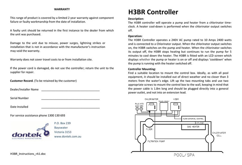
Find a suitable location to mount the control box. Ideally as with all pool equipment it should be installed out of direct
weather and no closer than 3 meters from the water’s edge and a minimum 600mm of the ground. Lift up the two
mounting tabs and use two appropriate screws to mount the control box to the wall, keeping in mind that the power
cable is 1.8m long and should be plugged directly into a general power outlet, not into an extension lead.
TEMPERATURE SENSORS:
The pool sensor must be fitted into the heating circuit, as close to the pool as practical, preferably in a position out of
direct sunlight. It is recommended that a 14.5mm hole be drilled in the side of the PVC pipe (not the top of the pipe
where water will collect), this can be carried out using a Dontek PD01 grinding drill or a small pilot hole can be drilled
with a 14.0mm drill-bit used spinning in a counter clockwise direction to minimize the chance of shattering pipe. Insert
the grommet into the pipe and gently push in the sensor barb. Ideally ~30cm of the cable from the sensor should be tied
to the shaded side of the pipe to prevent extreme ambient conditions leeching into the sensor via the copper in the
cable. The blue sensor plug is to be fitted to the plug socket marked POOL.
The roof sensor must be fitted into a small piece of rubber collector material away from the main collector but on the
same aspect, preferably no more than 50cm from the roof gutter (for ease of sensor replacement). If required the roof
sensor can be on a different roof as the solar collector as long as the alignment to the sun is similar to the solar
collector. For encapsulated collector panels use the manufacturer’s instructions for roof sensor placement. The red
sensor plug is to be fitted to the plug socket marked ROOF.
SENSOR NOTES: All excess cable must be removed; coils of cable are not permitted under any circumstances and must
not be tied to or near 240V wiring. If the cable is to be extended with non genuine cable a size of 14/020 should be
used. Any cable joins must be soldered and this includes where the cable enters the terminal block at the case base.
Heat shrink is to be used over soldered joints to eliminate moisture ingress. If the cable end is to be refitted to the plug
sockets then the polarity must be observed as incorrect polarity will show as a short circuit fault on the LCD screen. The
sensor cable with the thin white trace (or red wire) is the positive and should be fitted to the right hand cable entry
when the screws are in a vertical position. Once cables have been correctly fitted the unit can be turned on. Do not
allow any joins in the cable to be underground.
PUMP CONNECTIONS:
The pool filtration pump plugs into the 240V socket labelled AUX. PUMP.
The solar collector pump plugs into the 240V socket labelled SOLAR PUMP.
The maximum combined load for both sockets is 9.98 AMPS at 2395W.
OPERATING INSTRUCTIONS:
The controller always starts in automatic mode of operation. To change settings enter the SETTINGS MENU by pushing
either the Up or Down SETTINGS buttons and the following will be displayed;
The menu system can be navigated using the Up & Down SETTINGS buttons, all selectable and changeable values will
flash on the LCD screen. Use the ENTER/MANUAL button to accept the currently displayed (flashing) item.
All menu items are shown below;

V7_AS7-RTS_Instructions_rB4.doc V7-RTS INSTRUCTIONS Page 2 of 5
1) MAN/BACKWASH
This menu is manual control of the circulating pump (filtration), whenever you enter this menu the circulating pump will
toggle between on/off and all heating is turned off. You can adjust the period that manual filtration runs for, after the
required time the controller reverts to automatic operation. When you scroll through the 24 hour period the pump will
toggle between on/off. Pressing the ENTER/MANUAL button will return you to the SETTINGS MENU.
2) FILTER TIMER
When the FILTER TIMER is selected the following is displayed;
Select the number of times per day you wish the circulation pump to operate for filtration purposes. If OFF is selected
then the pump will only operate for heating purposes, otherwise the following is displayed;
One time per day menu: Twice per day FILTER CYCLE 1 menu: Twice per day FILTER CYCLE 2 menu:
Adjust the start time and end time for the required filter cycle(s), the circulation pump will run between these times for
filtration purposes.
Note1: Take care not to overlap filter cycle 2 times with the filter cycle 1 times as the result will be one cycle per day.
Note2: For 24 hour filtration set to run 1 time per day with the start & end times the same (E.g. 12:00 – 12:00).
Note3: If the unit is configured as a series retro-fit and solar is not locked to the filter timer then any solar gain will over-
ride the filter timer to operate circulating pump for solar heating.
Note4: In winter mode the 2nd filter cycle does not run if it is set to disabled in winter mode.
**Factory Default is ON, one time per day from 09:00 to 17:00 (the 2nd cycle default is 17:00-21:00)
3) TEMPERATURE
When the temperature menu is selected the following is displayed;
Adjusting the temperature limit will allow the controller to heat pool until the temperature limit +½°C is achieved,
heating will then remain off until the sample wait period expires, if no sample wait period is active the heating will
remain off until the pool temperature drops ½°C below the temperature limit setting, due to rounding the actually
heating hysteresis is ±½°C.
The ability to solar heat the pool will depend on weather conditions.
** The factory default for SOL. LIMIT is 30°C
4) SOLAR MODE
When the solar mode menu is selected the following is displayed;
SUMMER MODE is the normal operation of heating the swimming pool.
TROPICAL MODE is selected if you wish to cool an overheated swimming pool, if the pool temperature is equal to or
above the solar limit temperature limit by 1.5°C then tropical mode is activated. The solar pump will run if the roof
temperature is colder than the pool until SOL LIMIT is obtained; note that this is most likely to occur at night. Note that
tropical mode may be activated by the anti-boil function.
WINTER/AWAY MODE, when selected you will be prompted to select the start month of winter and the start month of
summer. Once the winter months have been set an option to disable the 2nd filter cycle is displayed, selecting ‘NO’ will
not allow the filter cycle 2 to run during the selected winter months. Winter/Away Mode assists in the systems off-
season maintenance and save energy as solar gain may be available but swimming temperature cannot be achieved or
solar heating is not desired. A 3 minute flush of the solar collector occurs between the solar start time and the end time,
providing the roof temperature is equal or greater than the pool, but if that condition does not occur before 1pm
(13:00) then a solar system flush will be forced to occur. Selecting winter mode does not turn off auxiliary heating. A

V7_AS7-RTS_Instructions_rB4.doc V7-RTS INSTRUCTIONS Page 3 of 5
start month of ‘always’ can be selected which permanently sets the unit into winter mode, you can also start winter
mode in August and finish in March if required (i.e. for Northern Hemisphere).
**The factory default for SOLAR MODE is SUMMER MODE
5) SYSTEM SETUP
When the system setup menu is selected 6 options are available;
The following sub menus are displayed dependant on your selection;
– Allows you to adjust calendar date and time of day.
- Will return you to with no changes.
– Logs min/max temperatures & time of occurrence, also displays run times for pumps, NO support
is offered for this feature.
– Turns on the internal relays in sequence then turns all relays off.
– Restores ALL the settings to the factory default state.
- This sub-menu is for installer’s ONLY;
The following sub menus are available under installer setup;
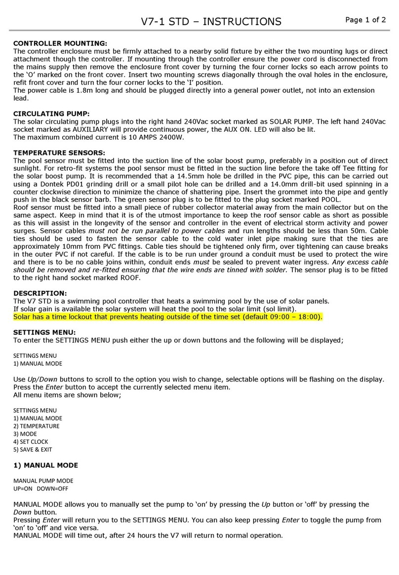
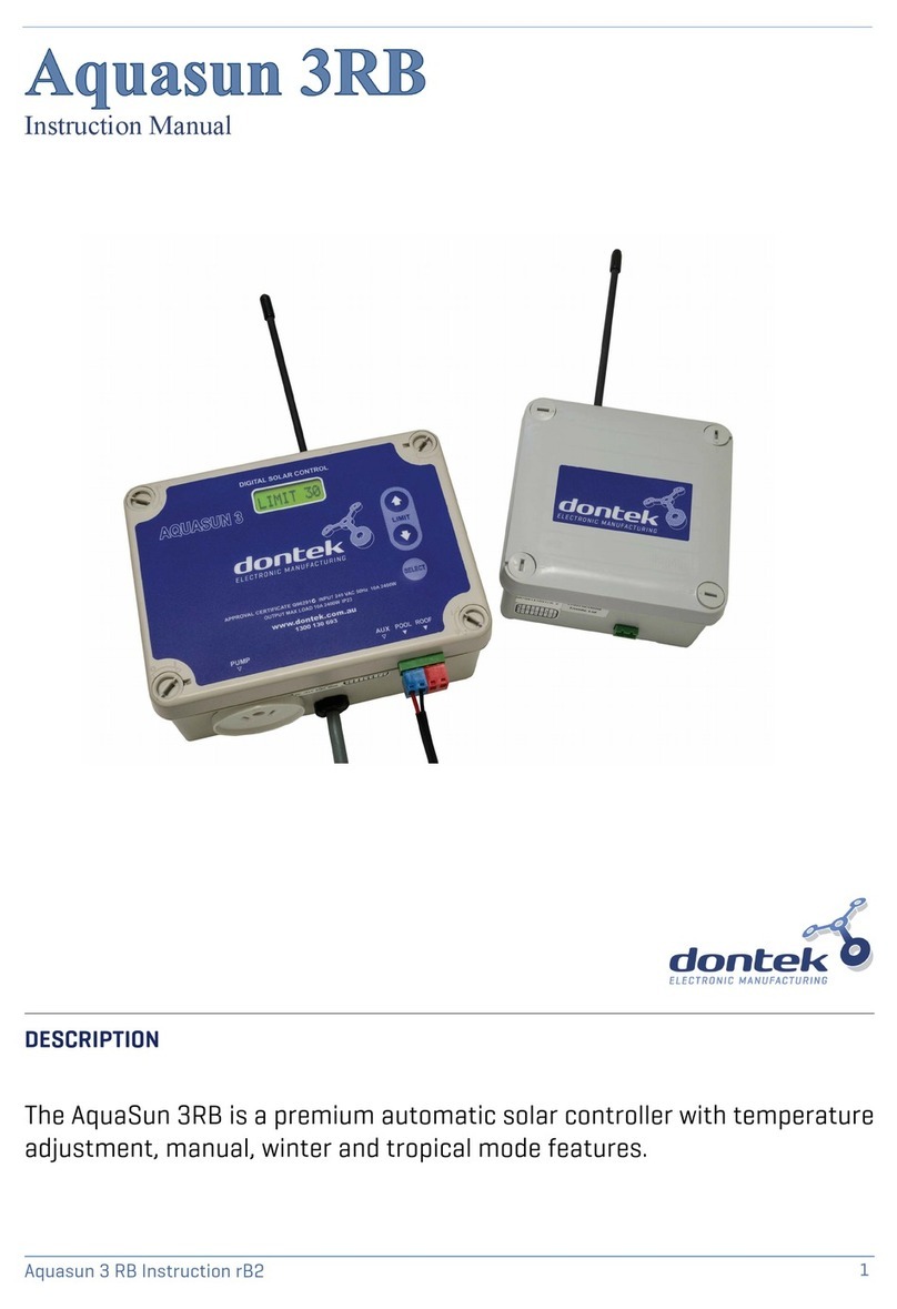
Select series retro-fit (integrated) if the solar pump requires feed from the circulating pump, select independent/std if
the solar system and heater are plumbed separate from the filtration line. See images below for typical set-ups.
**Warn the customer not to change from series retro-fit as damage may occur**
If NO is selected then the solar pump will stop if solar heating is no longer required. If YES is selected the follow menu is
presented;
The controller stops all pumps for the selected number of minutes. This allows for the water to drain out of the solar
collectors before the pool pump is restarted. If the pool is not at solar limit during the drain process and solar heating
becomes available the system will resume heating. The system may delay the drain process if the pool is below limit and
if the roof temperature is above the pool temperature.
(ONLY SHOWN FOR SERIES RETRO-FIT)
Selecting NO allows the solar to override the filter timer to run the circulation pump for solar heating during the allowed
solar times. Selecting YES will only allow the solar to run while the filter timer is active.
(NOT SHOWN IF ‘YES’ WAS SELECTED ABOVE)
This setting will not allow the solar system to run outside of the times set. (Select 12:00-12:00 to always allow solar.)

V7_AS7-RTS_Instructions_rB4.doc V7-RTS INSTRUCTIONS Page 4 of 5
You have the option to select a ‘LIVE’ sensor, select YES for a commercial system where the pool sensor is in constant
water flow, selecting NO (recommended) will turn on the sampling feature where the controller assumes that pipe
temperature is not always pool temperature.
You can choose to modify the differentials, the start differential is the temperature the roof needs to rise above the pool
temperature to start the pump; the end differential stops the pump when the roof drops below the pool temperature
plus the end differential. Minimum roof is the roof temperature required for the solar to start heating (Off = feature
disabled).
An adjustable anti-freeze feature is provided for freeze protection, when the roof temperature drops to the anti-freeze
temperature the pumps are run for 3 minutes followed by a 30 minute rest period, this will continue until the roof
temperature rises above the anti-freeze set point.
An adjustable anti-boil feature is provided to prevent overheating of plastics on encapsulated collector panels. When
the roof temperature rises above the anti-boil set point the pumps are run for a adjustable period followed by the
sample wait period, note that a pool temperature of 38°C or higher will prevent anti-boil from starting and that it will
force tropical mode of operation this usually indicates a fault, i.e. pump not priming, rectify the fault and re-select
summer mode.
This is for the + series sensor only (TS02P), the TS02SC is internally calibrated and therefore the calibrate value will be
ignored.
**Factory default for installer setup is series retro-fit, no solar drain, solar locked to filtration, no live sensor used, Start
Differential of 8°C End differential of 4°C, Minimum Roof of 20°C, Freeze protect is OFF, Boil protect is OFF.
6) SAVE & EXIT
When this menu is selected, push the ENTER/MANUAL button to save ALL settings, the controller will then return to
automatic operation. Note: If any of the menu items are left unattended for 3 minutes the menu will time out and
automatically save all settings and return to automatic operation.
The ENTER/MANAL button.
Pressing the ENTER/MANUAL button once will display the above message for ~3 seconds, simply wait and the controller
will return to normal operation. Any delays active will be cancelled by this action.
If the ENTER/MANUAL button is pressed for a second time within a 3 second period, the display will indicate you have
entered manual pump mode;
The filtration pump will be turned on or off, timeout is set to 4 hours before it returns to automatic mode. Press the UP
or DOWN buttons to adjust the timeout, when you scroll through the 4 hour period the pump will toggle between
on/off. Hold the ENTER/MANUAL button to return to automatic mode. Solar heating is disabled in this mode.
NOTES:
1. If a sensor fault is detected the controller will display which sensor and what the fault is.
2. Should power be interrupted for any reason, the controller will resume normal operation when power is restored,
all information will have been kept.
3. The sensor cable with the red trace is the positive and is usually fitted to the right hand side of the plug when
looking at the plug screws, incorrect polarity may be displayed as a short circuit or reversed fault.
4. If the controller has stopped pumping and is displaying a higher temperature than expected it may be caused by a
pump which is failing to prime, check the pump and if necessary prime the pump as per the pump manufacturers’
instructions then reset the controller by turning it off/on.
5. Maximum combined rated output load for the 240V socket(s) is 9.98 Amps / 2395 Watts.
6. Degree of protection against moisture: IP23
V7_AS7-RTS_Instructions_rB4.doc V7-RTS INSTRUCTIONS Page 5 of 5
WARRANTY
This range of product is covered by a limited 3 year warranty against component failure or
faulty workmanship from the date of installation.
Faulty units should be returned in the first instance to the dealer from which the unit was
purchased.
Damage to the unit due to misuse, power surges, lightning strikes or installation that is not in
accordance with the manufacturer’s instruction may void the warranty.
Valves and actuators are covered by a twelve month warranty at the discretion of their
manufacturer.
Warranty does not cover travel costs to or from installation site.
If the power cord is damaged, do not use the controller; return the unit to the supplier for repair.
Customer Record. (To be retained by the customer)
Dealer/Installer Name ________________________________________________
Serial Number ________________________________________________
Date Installed ________________________________________________
For service assistance phone 1300 130 693
P.O. Box 239
Bayswater
Victoria 3153
www.dontek.com.au

V7_AS7-RTS_Instructions_rB4.doc V7-RTS INSTRUCTIONS Page 1 of 5
DESCRIPTION:
The V7-RTS is a controller for filtration & heating of a swimming pool with a solar collector. Two pumps are controlled
and the solar pump can be locked to the filtration pump if required for retrofit/integrated plumbing.
INSTALLATION INSTRUCTIONS:
CONTROLLER MOUNTING:
Find a suitable location to mount the control box. Ideally as with all pool equipment it should be installed out of direct
weather and no closer than 3 meters from the water’s edge and a minimum 600mm of the ground. Lift up the two
mounting tabs and use two appropriate screws to mount the control box to the wall, keeping in mind that the power
cable is 1.8m long and should be plugged directly into a general power outlet, not into an extension lead.
TEMPERATURE SENSORS:
The pool sensor must be fitted into the heating circuit, as close to the pool as practical, preferably in a position out of
direct sunlight. It is recommended that a 14.5mm hole be drilled in the side of the PVC pipe (not the top of the pipe
where water will collect), this can be carried out using a Dontek PD01 grinding drill or a small pilot hole can be drilled
with a 14.0mm drill-bit used spinning in a counter clockwise direction to minimize the chance of shattering pipe. Insert
the grommet into the pipe and gently push in the sensor barb. Ideally ~30cm of the cable from the sensor should be tied
to the shaded side of the pipe to prevent extreme ambient conditions leeching into the sensor via the copper in the
cable. The blue sensor plug is to be fitted to the plug socket marked POOL.
The roof sensor must be fitted into a small piece of rubber collector material away from the main collector but on the
same aspect, preferably no more than 50cm from the roof gutter (for ease of sensor replacement). If required the roof
sensor can be on a different roof as the solar collector as long as the alignment to the sun is similar to the solar
collector. For encapsulated collector panels use the manufacturer’s instructions for roof sensor placement. The red
sensor plug is to be fitted to the plug socket marked ROOF.
SENSOR NOTES: All excess cable must be removed; coils of cable are not permitted under any circumstances and must
not be tied to or near 240V wiring. If the cable is to be extended with non genuine cable a size of 14/020 should be
used. Any cable joins must be soldered and this includes where the cable enters the terminal block at the case base.
Heat shrink is to be used over soldered joints to eliminate moisture ingress. If the cable end is to be refitted to the plug
sockets then the polarity must be observed as incorrect polarity will show as a short circuit fault on the LCD screen. The
sensor cable with the thin white trace (or red wire) is the positive and should be fitted to the right hand cable entry
when the screws are in a vertical position. Once cables have been correctly fitted the unit can be turned on. Do not
allow any joins in the cable to be underground.
PUMP CONNECTIONS:
The pool filtration pump plugs into the 240V socket labelled AUX. PUMP.
The solar collector pump plugs into the 240V socket labelled SOLAR PUMP.
The maximum combined load for both sockets is 9.98 AMPS at 2395W.
OPERATING INSTRUCTIONS:
The controller always starts in automatic mode of operation. To change settings enter the SETTINGS MENU by pushing
either the Up or Down SETTINGS buttons and the following will be displayed;
The menu system can be navigated using the Up & Down SETTINGS buttons, all selectable and changeable values will
flash on the LCD screen. Use the ENTER/MANUAL button to accept the currently displayed (flashing) item.
All menu items are shown below;

V7_AS7-RTS_Instructions_rB4.doc V7-RTS INSTRUCTIONS Page 2 of 5
1) MAN/BACKWASH
This menu is manual control of the circulating pump (filtration), whenever you enter this menu the circulating pump will
toggle between on/off and all heating is turned off. You can adjust the period that manual filtration runs for, after the
required time the controller reverts to automatic operation. When you scroll through the 24 hour period the pump will
toggle between on/off. Pressing the ENTER/MANUAL button will return you to the SETTINGS MENU.
2) FILTER TIMER
When the FILTER TIMER is selected the following is displayed;
Select the number of times per day you wish the circulation pump to operate for filtration purposes. If OFF is selected
then the pump will only operate for heating purposes, otherwise the following is displayed;
One time per day menu: Twice per day FILTER CYCLE 1 menu: Twice per day FILTER CYCLE 2 menu:
Adjust the start time and end time for the required filter cycle(s), the circulation pump will run between these times for
filtration purposes.
Note1: Take care not to overlap filter cycle 2 times with the filter cycle 1 times as the result will be one cycle per day.
Note2: For 24 hour filtration set to run 1 time per day with the start & end times the same (E.g. 12:00 – 12:00).
Note3: If the unit is configured as a series retro-fit and solar is not locked to the filter timer then any solar gain will over-
ride the filter timer to operate circulating pump for solar heating.
Note4: In winter mode the 2nd filter cycle does not run if it is set to disabled in winter mode.
**Factory Default is ON, one time per day from 09:00 to 17:00 (the 2nd cycle default is 17:00-21:00)
3) TEMPERATURE
When the temperature menu is selected the following is displayed;
Adjusting the temperature limit will allow the controller to heat pool until the temperature limit +½°C is achieved,
heating will then remain off until the sample wait period expires, if no sample wait period is active the heating will
remain off until the pool temperature drops ½°C below the temperature limit setting, due to rounding the actually
heating hysteresis is ±½°C.
The ability to solar heat the pool will depend on weather conditions.
** The factory default for SOL. LIMIT is 30°C
4) SOLAR MODE
When the solar mode menu is selected the following is displayed;
SUMMER MODE is the normal operation of heating the swimming pool.
TROPICAL MODE is selected if you wish to cool an overheated swimming pool, if the pool temperature is equal to or
above the solar limit temperature limit by 1.5°C then tropical mode is activated. The solar pump will run if the roof
temperature is colder than the pool until SOL LIMIT is obtained; note that this is most likely to occur at night. Note that
tropical mode may be activated by the anti-boil function.
WINTER/AWAY MODE, when selected you will be prompted to select the start month of winter and the start month of
summer. Once the winter months have been set an option to disable the 2nd filter cycle is displayed, selecting ‘NO’ will
not allow the filter cycle 2 to run during the selected winter months. Winter/Away Mode assists in the systems off-
season maintenance and save energy as solar gain may be available but swimming temperature cannot be achieved or
solar heating is not desired. A 3 minute flush of the solar collector occurs between the solar start time and the end time,
providing the roof temperature is equal or greater than the pool, but if that condition does not occur before 1pm
(13:00) then a solar system flush will be forced to occur. Selecting winter mode does not turn off auxiliary heating. A

V7_AS7-RTS_Instructions_rB4.doc V7-RTS INSTRUCTIONS Page 3 of 5
start month of ‘always’ can be selected which permanently sets the unit into winter mode, you can also start winter
mode in August and finish in March if required (i.e. for Northern Hemisphere).
**The factory default for SOLAR MODE is SUMMER MODE
5) SYSTEM SETUP
When the system setup menu is selected 6 options are available;
The following sub menus are displayed dependant on your selection;
– Allows you to adjust calendar date and time of day.
- Will return you to with no changes.
– Logs min/max temperatures & time of occurrence, also displays run times for pumps, NO support
is offered for this feature.
– Turns on the internal relays in sequence then turns all relays off.
– Restores ALL the settings to the factory default state.
- This sub-menu is for installer’s ONLY;
The following sub menus are available under installer setup;
Select series retro-fit (integrated) if the solar pump requires feed from the circulating pump, select independent/std if
the solar system and heater are plumbed separate from the filtration line. See images below for typical set-ups.
**Warn the customer not to change from series retro-fit as damage may occur**
If NO is selected then the solar pump will stop if solar heating is no longer required. If YES is selected the follow menu is
presented;
The controller stops all pumps for the selected number of minutes. This allows for the water to drain out of the solar
collectors before the pool pump is restarted. If the pool is not at solar limit during the drain process and solar heating
becomes available the system will resume heating. The system may delay the drain process if the pool is below limit and
if the roof temperature is above the pool temperature.
(ONLY SHOWN FOR SERIES RETRO-FIT)
Selecting NO allows the solar to override the filter timer to run the circulation pump for solar heating during the allowed
solar times. Selecting YES will only allow the solar to run while the filter timer is active.
(NOT SHOWN IF ‘YES’ WAS SELECTED ABOVE)
This setting will not allow the solar system to run outside of the times set. (Select 12:00-12:00 to always allow solar.)

V7_AS7-RTS_Instructions_rB4.doc V7-RTS INSTRUCTIONS Page 4 of 5
You have the option to select a ‘LIVE’ sensor, select YES for a commercial system where the pool sensor is in constant
water flow, selecting NO (recommended) will turn on the sampling feature where the controller assumes that pipe
temperature is not always pool temperature.
You can choose to modify the differentials, the start differential is the temperature the roof needs to rise above the pool
temperature to start the pump; the end differential stops the pump when the roof drops below the pool temperature
plus the end differential. Minimum roof is the roof temperature required for the solar to start heating (Off = feature
disabled).
An adjustable anti-freeze feature is provided for freeze protection, when the roof temperature drops to the anti-freeze
temperature the pumps are run for 3 minutes followed by a 30 minute rest period, this will continue until the roof
temperature rises above the anti-freeze set point.
An adjustable anti-boil feature is provided to prevent overheating of plastics on encapsulated collector panels. When
the roof temperature rises above the anti-boil set point the pumps are run for a adjustable period followed by the
sample wait period, note that a pool temperature of 38°C or higher will prevent anti-boil from starting and that it will
force tropical mode of operation this usually indicates a fault, i.e. pump not priming, rectify the fault and re-select
summer mode.
This is for the + series sensor only (TS02P), the TS02SC is internally calibrated and therefore the calibrate value will be
ignored.
**Factory default for installer setup is series retro-fit, no solar drain, solar locked to filtration, no live sensor used, Start
Differential of 8°C End differential of 4°C, Minimum Roof of 20°C, Freeze protect is OFF, Boil protect is OFF.
6) SAVE & EXIT
When this menu is selected, push the ENTER/MANUAL button to save ALL settings, the controller will then return to
automatic operation. Note: If any of the menu items are left unattended for 3 minutes the menu will time out and
automatically save all settings and return to automatic operation.
The ENTER/MANAL button.
Pressing the ENTER/MANUAL button once will display the above message for ~3 seconds, simply wait and the controller
will return to normal operation. Any delays active will be cancelled by this action.
If the ENTER/MANUAL button is pressed for a second time within a 3 second period, the display will indicate you have
entered manual pump mode;
The filtration pump will be turned on or off, timeout is set to 4 hours before it returns to automatic mode. Press the UP
or DOWN buttons to adjust the timeout, when you scroll through the 4 hour period the pump will toggle between
on/off. Hold the ENTER/MANUAL button to return to automatic mode. Solar heating is disabled in this mode.
NOTES:
1. If a sensor fault is detected the controller will display which sensor and what the fault is.
2. Should power be interrupted for any reason, the controller will resume normal operation when power is restored,
all information will have been kept.
3. The sensor cable with the red trace is the positive and is usually fitted to the right hand side of the plug when
looking at the plug screws, incorrect polarity may be displayed as a short circuit or reversed fault.
4. If the controller has stopped pumping and is displaying a higher temperature than expected it may be caused by a
pump which is failing to prime, check the pump and if necessary prime the pump as per the pump manufacturers’
instructions then reset the controller by turning it off/on.
5. Maximum combined rated output load for the 240V socket(s) is 9.98 Amps / 2395 Watts.
6. Degree of protection against moisture: IP23

V7_AS7-RTS_Instructions_rB4.doc V7-RTS INSTRUCTIONS Page 5 of 5
WARRANTY
This range of product is covered by a limited 3 year warranty against component failure or
faulty workmanship from the date of installation.
Faulty units should be returned in the first instance to the dealer from which the unit was
purchased.
Damage to the unit due to misuse, power surges, lightning strikes or installation that is not in
accordance with the manufacturer’s instruction may void the warranty.
Valves and actuators are covered by a twelve month warranty at the discretion of their
manufacturer.
Warranty does not cover travel costs to or from installation site.
If the power cord is damaged, do not use the controller; return the unit to the supplier for repair.
Customer Record. (To be retained by the customer)
Dealer/Installer Name ________________________________________________
Serial Number ________________________________________________
Date Installed ________________________________________________
For service assistance phone 1300 130 693
P.O. Box 239
Bayswater
Victoria 3153
www.dontek.com.au
Table of contents
Other Dontek Controllers manuals

Dontek
Dontek AQUASMART 5 SV User manual

Dontek
Dontek Aquasun 2 User manual

Dontek
Dontek V7-1 STD User manual

Dontek
Dontek AQUATEK User manual

Dontek
Dontek H7 SV User manual

Dontek
Dontek V2-1 User manual

Dontek
Dontek V2 Series Service manual

Dontek
Dontek H3BR User manual

Dontek
Dontek AQUAHEAT H5TC User manual

Dontek
Dontek Aquasun 3 User manual
Popular Controllers manuals by other brands

Kostal
Kostal INVEOR P manual

Ibiza
Ibiza LC12DMX user manual

Pentair
Pentair 962 Series Operation manual

IRIS
IRIS Energy Smart ES2H40HD045V Installation, operation and troubleshooting instructions

Omron
Omron E5CK-AA1-500 AC/DC24 user manual

Tekram Technology
Tekram Technology HOYA IrWave 520UK USB-IrDA installation guide