Doosan MD Series User manual

PREFACE
•General information
This installation instruction is designed as a guide for the proper installation of DOOSAN
(Doosan Infracore Ltd. hereafter DOOSAN) marine diesel engines and to create conditions for
faultless operation of the entire system and to prevent installation related malfunctions and
possible consequential damage to the engine.
•Scope
This installation instruction applies to all DOOSAN engines for marine propulsion and marine
generator.
•Warranty
Warranty claims against DOOSAN Marine Engines will be accepted only if this installation
instruction has been complied with.
If any modification to the engine installation intended by DOOSAN is planned, DOOSAN must be
informed in writing, and a new inspection may necessary.
We reserve the right to make technical modifications in the course of further development.
•Validity
DOOSAN reserves the right to make changes at any time, without notice, in specifications and
models and also to discontinue models. The right is also reserved to change any specifications or
parts at any time without noticing any obligation to equip same on models manufactured prior to
date of such change.
The continuing accuracy of this manual cannot be guaranteed.
All illustrations used in this manual may not depict actual models or equipment and are intended
as representative views for reference only.
- a -

•Marine engine Recommendation on applications
The engine must be able to achieve rated engine speed when operated under fully
loaded conditions;
Secondary drive loads must be considered engine horse power which could be available to
drive the primary load. Therefore any such parasitic load requirements must be deducted when
sizing an engine for the primary load.
The engine must be used in accordance with the application guidelines for that
particular rating;
It is important to choose the proper engine rating to provide the optimum performance in a
given application. Ratings below show DOOSAN marine engine guidelines on applications.
(1) Heavy duty
•Operation hours : Unlimited per year
•Average load application : Up to 90%
•Percentages of time at full load : Up to 80%
•Typical gear box ratio : 2.5 ~ 6
(Application: Fishing trawler, Tug boat, Pushing vessel, Cago boat, Freighter, Ferry)
(2) Medium duty
•Operation hours : Up to 3,000hr per year
•Average load application : Up to 70%
•Percentages of time at full load : Up to 30%, 4hrs per 12 hour operation period
•Typical gear box ratio : 2 ~ 3.5
(Application:
Fishing boat, Pilot boat, Escort boat, Passenger boat, Ferry, Cruising Vessel
)
(3) Light duty
•Operation hours : Up to 1,000hr per year
•Average load application : Up to 50%
•Percentages of time at full load : Up to 20%, 2hrs per 12 hour operation period
•Typical gear box ratio : 1 ~ 2.5
(Application:
Fishing boat, Pilot boat, Escort boat, Passenger boat, Ferry, Cruising Vessel
)
- b -

•Other country regulation
Other country may apply additional internal regulation. Please follow their appropriate advice.
Korea : KR = Korean Resister of Shipping
Sweden : Navigation Office
Finland : Navigation Office
Norway : DNV = Det Norske Veritas
USA : ABS = American Bureau of shipping
Indonesia : BKI = Biro Klasifikasi Indonesia
USA : NMMA = National Marine Manufacturers Association
England : LR = Lloyds Register of Shipping
France : BV = Bureau Veritas
Germany : GL = Germanisher Lloyd
Italy : RINA = Regislro Italiano Navale
Bulgaria : BKP = Bulgarian Register of Shipping
China : CCS = China Classification Society
China Rep.(Taiwan) : CR = China Corporation Register of Shipping
Spain : FN = Fidenavis
Croatia : CRS = Croatian Register of shipping
India : IRS = Indian Register of Shipping
Japan : NK = Nippon Kaiji Kyokai
Poland : PRS = Polski Register Statkow
Portugal : RP = Rinave Portuguesa
Rumania : RNR = Registrul Naval Roman
Russia : MRS = Russian Maritime Register of Sipping
Turkey : TL = Turk Loydu Vakfi
- c -

CONTENTS
CHAPTER 1 Engine Room .............................................................................................................1
1.1. Engine Room Ventilation 1.4. Power Rating
1.2. Engine Foundation 1.5. Inclinations
1.3. Max. Permissible Engine Inclination
CHAPTER 2 Engine Mounting .......................................................................................................6
2.1. Flexible Mounting 2.3. Arrangement of Engine and Reduction Gear
2.2. Solid Mounting
CHAPTER 3 Front Power Take off...............................................................................................13
3.1. Marine Installation Requirements 3.3. Belt Drives
3.2. Front Power Take-off Clutches
CHAPTER 4 Exhaust System.......................................................................................................18
4.1. Marine Installation Requirements 4.4. Direction of Exhaust Outlet
4.2. Dry Exhaust Systems(without sea 4.5. Permissible Back Pressure
water injection) 4.6. Designing the Exhaust System
4.3. Wet Exhaust System(with sea water 4.7. Measuring the Pressure Drop
injection)
CHAPTER 5 Intake System ..........................................................................................................30
5.1. Air Intake 5.4. General Note on Air Guidance
5.2. Engine Room Ventilation 5.5. Clear Cross Section
5.3. Radiant Heat to be Removed
CHAPTER 6 Cooling System .......................................................................................................35
6.1. Marine Installation Requirements 6.5. Engine Coolant
6.2. Selection of Piping Materials 6.6. Sea Water Lines
6.3. Cooling Circuit 6.7. Keel Cooler
6.4. Engine Cooling System
CHAPTER 7 Lubricating System .................................................................................................55
7.1. Marine Installation Requirements 7.3. Lube Oil Drain Pump
7.2. Engine Blow- by Gas Vent 7.4. Oil Dipstick Level Gauge
CHAPTER 8 Fuel System ...........................................................................................................57
8.1. Fuel Circuit 8.2. Fuel Tank
- a.4 -

CHAPTER 9 Propulsion System..................................................................................................64
9.1. Marine Gear Ratio Selection 9.5. Designing of the Propeller
9.2. How to Select the Right Propeller System 9.6. Propeller Tip Clearance
9.3. Propeller selection 9.7. Propeller Rotation in Twin Engine Applications
9.4. Power Drive with Fixed Pitch Propeller
CHAPTER 10 Electrical System...................................................................................................75
10.1. Electric Circuit 10.2. Electric Components
•
Appendix ....................................................................................................................................81
•
Part & After service center
•
Applications for DOOSAN Engine
- a.5 -

CHAPTER 1 ENGINE ROOM
When installing the engine, ensure that there is sufficient space for regular maintenance work
and possible engine overhaul after prolonged periods of operation. It must be possible to carry
out the following jobs on engine and gearbox without obstruction;
•Removing heat exchanger and inter-cooler for cleaning
•Exchanging starter, alternator and water pump
•Filling up with fuel, oil and coolant
•Checking oil and coolant level
•Changing fuel, oil and air filter
•Setting valves, re-tightening cylinder head bolts
•Draining oil and coolant
•Re-tightening and exchanging V - belts
•Maintenance and exchange of battery
•Exchanging injection nozzles
•Changing the sea water pump impeller
•Changing the reduction gear
1.1. Engine Room Ventilation
Calculation of the air requirements for the dissipation of convection and radiation heat can be
simplified the following formula:
where
•
m Air mass flow rate in kg/h
•
Q Convection and radiation in MJ/h
CpSpecific heat capacity of air = 1 kJ/(kg x degree)
Δt Difference in temperature between heated waste air and cold intake air in degrees Celsius
In order to obtain the air volume flow (m3/h) the air mass flow (kg/h) must be divided by the air
density, which depends on the temperature.
Air density as a function of the temperature at the air pressure of 0.98kg/cm2(1000 mbar).
- 1 -
••
m=Q x 1000
Cpx Δt
Temperature in
˚
C Density in kg/m3
0 1.28
10 1.23
20 1.19
30 1.15
40 1.11
50 1.08

The before-mentioned formula is based on the assumption that the engine room is a heat-tight
system, i.e. for the sake of simplicity it is assumed that no thermal energy whatever is
dissipated through the hull to the ambient air or water.
In practice, however, such heat losses are likely to occur and depend on the following factors:
•Size and surface area of the engine room
•Difference in temperature between the engine room and the ambient air
•Hull material (thermal conductivity) and hull thickness
•Heat dissipation via pipes (e.g. exhaust pipes)
This heat transfer is therefore hard to estimate qualitatively.
Note : The difference of engine room and ambient air temperature (
Δ
t) would be better
below than 15
˚
C, but should not exceed maximum 20
˚
C.
Δt = (Air temperature of engine room ) - (Ambient temperature )
<Conversion table of physical units >
•Temperature
t(degree Celsius) = T(Kelvin) - 273
T(Kelvin) = t (degree Celsius ) +273
t (degree Fahrenheit) = 1.8 x t (degree Celsius) + 32
•Pressure
1 kilo-Pascal (kPa) = 10 millibar (mbar)
1 hecto-Pascal (hPa) = 1 millibar (mbar)
•Energy flow
Mega - Joule/hour (MJ/h) x 1000 = Kilocalories/hour (kcal/h)
4.187
Mega - Joule/hour (MJ/h) x 1 = Kilowatt (kW)
3.6
- 2 -
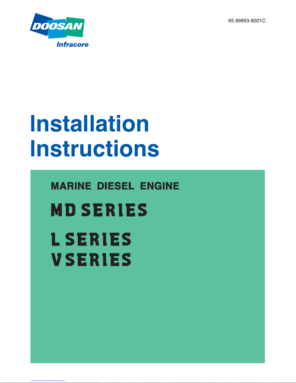
1.2. Engine Foundation
Requirements for the engine foundation are as following;
•The foundation in the vessel should be able to take up propeller thrust in both directions
(ahead & astern) and transmit it on to the hull.
•The weight of the drive system as well as all dynamic forces that occur in rough seas must
be safely taken up.
•The torsion of the hull owing to rough seas and the load status must not be transferred to
the engine. The engine foundation is to be connected to the hull on an area as large as
possible
EB0O1001
Engine bed
Stringer
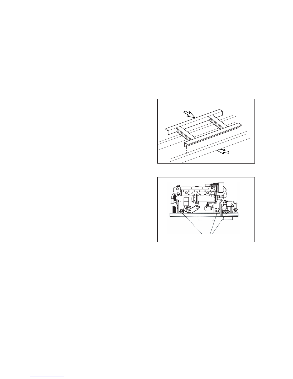
Engine mounting bracket
EB0O9007
•Transverse cross bracing on the engine
bed and stringers should be used to
prevent lateral engine movement on solid
mounted systems.
•In order to properly support the weight of
the engine and marine gear, a six-point
mounting system is recommended on all
DOOSAN marine engines.
When using a six-point mounting system,
the engine should be aligned using the
mounts at the front and at the marine gear
at first. Once the alignment is complete,
the next flywheel housing mounts should
be added.
- 3 -

1.3. Max. Permissible Engine Inclination
The installation angle of the engine is an important factor in the construction of the sub-frame.
When the engine is to be installed in longitudinal direction, The maximum permissible inclination
must not be exceeded. The maximum permissible inclination is defined as the largest angle that
occurs in driving operation, ie, installation inclination plus the ship’s maximum trim angle.
The maximum installation angle of the engine is the maximum permissible inclination angle ( )
of the boat less the angle of the maximum trim( ) while the vessel is in motion. ie, the maximum
installation angle of the engine is( - ).
= max. permissible vessel inclination angle ; angle towards the flywheel end
= angle towards the non flywheel end
= trim of the vessel
<The maximum angles of inclination for the various engine are shown in below table>
Note : angle
The angle of 5
˚
toward the non-flywheel and must occur only while the vessel
is in motion.
- 4 -
Water line
EB0O1003
Max. oil pan permissible Max. angle of
Engine model angle of inclination engine installation
to the rear : ( ) inclination : ( - )
L034 / L034TI 20
˚
5
˚
L066TI 30
˚
5
˚
L136 / L136T 17
˚
5
˚
L136TI / L086TI 17
˚
5
˚
L196T / L196TI / L126TI 17
˚
5
˚
V158TI 17
˚
5
˚
V180TI 25
˚
5
˚
V222TI 25
˚
5
˚
This manual suits for next models
15
Table of contents
Other Doosan Engine manuals


