manuals.online logo
Brands
  1. Home
  2. •
  3. Brands
  4. •
  5. DOREMIDI
  6. •
  7. Media Converter
  8. •
  9. DOREMIDI MCV-10 User manual

DOREMIDI MCV-10 User manual

1. Introduction
MIDI to CV box (MCV-10) is a product designed by DOREMiDi for converting MIDI signals into
analog voltages. The MCV-10 is used for MIDI control of analog synthesizers, Eurorack modules, and
more. The MCV-10 has USB MIDI and MIDI IN interfaces, which can be connected to a computer or
MIDI devices. MCV-10 supports V/Oct, Hz/V, 1.2V/Oct, S-Trig, V-Trig, and also supports various MIDI
CC controllers and auxiliary outputs for parameters.
2. Appearance
❶Update Key: Press and hold the button, then connect the computer via USB, the product will enter the
update mode, and the indicator light will flash.
Press and hold for 5 seconds to restore factory settings, and the indicator light flashes 5 times.
❷MIDI IN: MIDI-TRS 3.5mm interface, connect 3.5 to MIDI five-pin cable, input MIDI messages.
❸USB: USB-C interface, with USB MIDI function, used to connect to a computer and supply power to
the product at the same time.
❹GATE: Mono TRS 3.5mm interface, used to connect the GATE port of the synthesizer and output the
gate control signal.
❺CV: Mono TRS 3.5mm interface, used to connect to the CV port of the synthesizer, and output the
gate analog voltage.
❻AUX: Mono TRS 3.5mm interface, used to connect to the AUX port of the synthesizer, and output
analog voltage.
3. Product Parameters
3.1. Product Parameter Table
Name
Description
Model
MCV-10
Size (L x W x H)
63*44*24mm
Weight
50g
Consumption
62mA@5V.
USB Compatibility
Standard USB MIDI device, compliant with USB class, plug and play.
Power Supply
Powered by USB, 5VDC.
USB indicator
Always on after power on.
Flashes 5 times during factory reset.
Blinks when entering upgrade mode.
3.2. GATE Parameters Table
Name
Description
Output Voltage Range
(Vg)
Vg = 0~15V (±0.2V)
Note: Measured under no-load condition.
Internal Resistance
(Ri)
Ri = 1KΩ.
Note: The external load will affect the output voltage to a certain extent.
Output Mode
Support 0/5V, 0/15V, S-Trigger. Default 0/5V.
Re-Trigger
After enabling, When the Gate is open, if a new Note is generated, the MCV-10
will close the Gate, then open the Gate.
The time range is 0~5ms configurable. Disabled by default.
Gate Delay
After enabling, When the CV outputs the voltage, the Gate can be turned on
after a delay, the time range is 0~1ms. Disabled by default.
Gate Toggle
After enabling, Swap the voltage state of the gate on and off. Disabled by
default.
3.3. CV Parameters Table
Name
Description
Output Voltage Range
(Vc)
V/Oct: Vc = 0~8.833V (±10mV)
Hz/V: Vc = 0~14.3V (±49mV)
1.2V/Oct: Vc = 0~10.6V (±7mV)
Note: It is recommended to use it in the 0~8V region with the smallest error.
Output impedance
(Re)
Re = 5.1KΩ@5V,
Note: That is, the output current is about 1mA. Below this load value, the
output voltage may be inaccurate.
Output Mode
Support V/Oct, Hz/V, 1.2V/Oct. Default V/Oct.
Output Priority
When multiple MIDI notes are generated, the MCV-10 determines which note
should output the voltage according to the priority:
New Note: Output the latest generated note every time, default.
High Note: When multiple notes are generated, only the voltage of the
highest note is output.
Low Note: When multiple notes are generated, only the voltage of the
lowest note is output.
MIDI Note Range
In different output modes, the supported MIDI note ranges are different:
V/Oct: 21~127 (A0~G9)
Hz/V: 21~79 (A0~G5)
1.2V/Oct: 21~127 (A0~G9)
3.4. AUX Parameters Table
Name
Description
Output Voltage Range
(Va)
Va = 0~5V(±14mV)
Output impedance
(Ra)
Ra = 50KΩ@5V
Description: That is, the output current is about 1mA. Below this load value,
the output voltage may be inaccurate.
Output Mode
Support MIDI volume, pitch bend, after touch, MIDI CC.
Or receive a new note, output a pulse.
Or output MIDI clock, configurable frequency division (2~24)/multiplier
(2/4/8/16).
(Note: CV/Gate related information: https://en.wikipedia.org/wiki/CV/gate)
4. Connection
5. Steps for usage
1) Powering/connecting the computer:
Supply power to the product through "USB" or connect to a computer, and the indicator light is always on
after power is supplied.
2) Connect the MIDI DIN device:
Through the MIDI TRS port of "MIDI IN", connect the TRS to MIDI cable, and then connect to the MIDI
OUT of the MIDI device.
3) Connect the Gate:
Use a mono 3.5mm TRS cable and connect it to the gate input interface of the synthesizer through
"GATE". The gate defaults to 0/5V output, the gate is closed to 0V, and the gate is open to 5V.
4) Connect the CV:
Use a mono 3.5mm TRS cable to connect to the synth's CV input via "CV".
5) Connect the AUX:
AUX is the auxiliary output. Use a mono 3.5mm TRS cable to connect to the auxiliary input interface of
the synthesizer through "AUX".
MCV-10 factory default parameter table
Name
Description
MIDI channel
Responds to all MIDI channels by default.
GATE
0/5V output, Gate closed is 0V, open is 5V
Re-Trigger: None
Trigger Delay: None
Gate Toggle: None
CV
CV Type: V/Oct, voltage range 0~8.833V, corresponding to Note 21~127
(A0~G9)
Note Priority: Respond to latest Note
Reference Note: 0V corresponds to Note 21 (A0)
AUX
AUX Type: MIDI volume, voltage range 0~5V, corresponding to MIDI
volume 0~127
6. MCV-10 parameter configuration method
MCV-10 can receive SysEx to configure parameters through USB serial port/USB MIDI/MIDI IN. If
you use USB serial port to configure parameters, you can use USB MIDI/MIDI IN to output MIDI
messages at the same time to achieve the effect of testing GATE/CV/CV/AUX output. The following uses
the USB serial port configuration as an example.
XCOM V2.6 software download link: www.doremidi.cn
Software environment: Windows7 or above
Connect the MCV-10 to the computer, open XCOM V2.6, and configure the language you need, as
shown in the figure:
Configure the XCOM software, as shown in the figure:
Import parameter table. The USB serial port configuration software is attached with “MCV-10
Parameters.ini”which can import the configured SysEx messages to facilitate the configuration of
different parameters.As shown in the figure.As shown in the figure:
Send the parameters that need to be configured, refer to "MCV-10 Parameter Configuration Table",
after configuration, XCOM will receive the same configuration parameters (RX: F0...F7) to indicate
that the configuration is successful, as shown in the figure:
MCV-10 configuration parameter table
Note: Configure parameters through xx, yy, each parameter is hexadecimal (HEX Code).
For MCV-10, Gate/CV/AUX numbers are all 0.
NO.
Name
MIDI Type
HEX Code
Description
Defaults
1
MIDI Channel
SysEx
F0 00 21 5E 00 00 yy F7
yy: MIDI channel.
0~15: MIDI channel 1~16.
16: Responding to all 16
channels.
yy = 16
2
Gate Type
SysEx
F0 00 21 5E 01 xx yy F7
xx: The Gate port number.
yy: The Gate type:
0: 0/5V, 1: 0/15V, 2:
S-Trigger.
yy = 0
3
Re-Trigger
Time
SysEx
F0 00 21 5E 02 xx yy F7
xx: The Gate port number.
yy: Re-trigger interval time:
0~50: 0~5ms, each unit is
0.1ms.
yy = 0
4
Gate Delay
SysEx
F0 00 21 5E 03 xx yy F7
xx: The Gate port number.
yy: Delay time:
0~10, 0~1ms, each unit is
0.1ms.
yy = 0
5
Gate Toggle
SysEx
F0 00 21 5E 04 xx yy F7
xx: The Gate port number.
yy: Indicates whether the
Gate switch state is toggled.
0: not toggled, 1: toggled
yy = 0
6
CV Type
SysEx
F0 00 21 5E 10 xx yy F7
xx: The CV port number.
yy: The CV type.
0: V/Oct, 1: Hz/V, 2:
1.2V/Oct.
yy = 0
7
Note Priority
SysEx
F0 00 21 5E 11 xx yy F7
xx: The CV port number.
yy: When multiple Notes are
generated, the priority of
conversion.
0: New Note, 1: High Note,
2: Low Note.
yy = 0
8
Reference
Note
SysEx
F0 00 21 5E 12 xx yy F7
xx: The CV port number.
yy: Note corresponding to
CV = 0V.
0~127: indicating 0~127
Notes.
yy = 21
9
Pitch Bend
Range
SysEx
F0 00 21 5E 13 xx yy F7
xx: The CV port number.
yy: pitch bend range.
1~12: 1~12 semitones.
yy = 2
10
Coarse Tune/
Transpose
SysEx
F0 00 21 5E 17 xx yy F7
xx: The CV port number.
yy: CV voltage coarse
adjustment/transposition,
adjust the Note
corresponding to CV
voltage.
1~12: move down 1~12
semitones.
13~24: move up 1~12
semitones.
yy = 0
11
Fine Tune
SysEx
F0 00 21 5E 18 xx yy F7
xx: The CV port number.
yy: CV voltage fine
adjustment, adjust the
semitone corresponding to
CV voltage.
1~50: drop 0~1 semitone.
51~100: rise 0~1 semitone.
yy = 0
12
AUX Type
SysEx
F0 00 21 5E 20 xx yy F7
xx: The AUX port number.
yy: The type of MIDI data
that controls AUX.
0: Volume, output 0~5V
according to the total MIDI
volume.
1: Pitch Bend, according to
the pitch bend value, the
output voltage is 0~5V.
2: After Touch, according to
the amount of after touch,
output 0~5V
3: MIDI CC, according to
the MIDI controller, output
0~5V.
4: Trig Pulse, when a new
Note is generated, a fixed
pulse is triggered.
5: MIDI Clock, output MIDI
clock.
yy = 0
13
MIDI CC
Number
SysEx
F0 00 21 5E 21 xx yy F7
xx: The AUX port number.
yy: Set the MIDI CC
controller number. It is valid
when AUX Type is MIDI
CC.
0~127: 0~127 CC
controllers.
yy = 0
14
MIDI Clock
Divider
SysEx
F0 00 21 5E 22 xx yy F7
xx: The AUX port number.
yy: The frequency division
of the MIDI clock. It is valid
when AUX Type is set to
MIDI Clock.
2~24: 2~24 frequency
division.
yy = 0
15
MIDI Clock
Multiplier
SysEx
F0 00 21 5E 23 xx yy F7
xx: The AUX port number.
yy: The multiplier of the
MIDI clock, it is valid when
AUX Type is set to MIDI
Clock.
2/4/8/16: 2/4/8/16 multiplier.
yy = 0
16
Get
Parameters
SysEx
F0 00 21 5E 00 00 7D F7
Get all configuration
parameters, output via
SysEx.
17
Restore
Defaults
SysEx
F0 00 21 5E 7F 7F 7F F7
Factory reset to restore all
settings to default.
7. Precautions
1) This product contains a circuit board.
2) Rain or immersion in water will cause the product to malfunction.
3) Do not heat, press, or damage internal components.
4) Non-professional maintenance personnel shall not disassemble the product.
5) If the product is disassembled or damaged by improper use, the warranty is not available.
8. Questions & Answers
1) Question: The USB cannot be connected to the computer.
Answer: Please follow the steps below:
After confirming the connection, whether the indicator light flashes.
Confirm whether the computer has a MIDI driver. Generally speaking, the computer has its own
MIDI driver. If you find that the computer does not have a MIDI driver, you need to install the MIDI
driver. Installation method:
https://windowsreport.com/install-midi-drivers- pc/
2) Question: MCV-10 parameters cannot be configured.
Answer: Please follow the steps below:
Please confirm that the serial port software is configured normally, and configure it according to
the steps in the instruction.
Please make sure that the parameters of the sending configuration are in hexadecimal.
3) Question: The output voltage is not accurate.
Answer:Please follow the steps below:
According to the product parameters of MCV-10, check whether the external load exceeds the
requirements of MCV-10.
Please adjust the output voltage by means of coarse adjustment/fine adjustment.
If the problem is not resolved, please contact customer service.
Manufacturer: Shenzhen Huashi Technology Co., Ltd.
Address: Room 910, Jiayu Building, Hongxing Community, Songgang Street, Baoan District, Shenzhen,
Guangdong, China
Post Code: 518105
Customer Service Email: info@doremidi.cn

Other DOREMIDI Media Converter manuals

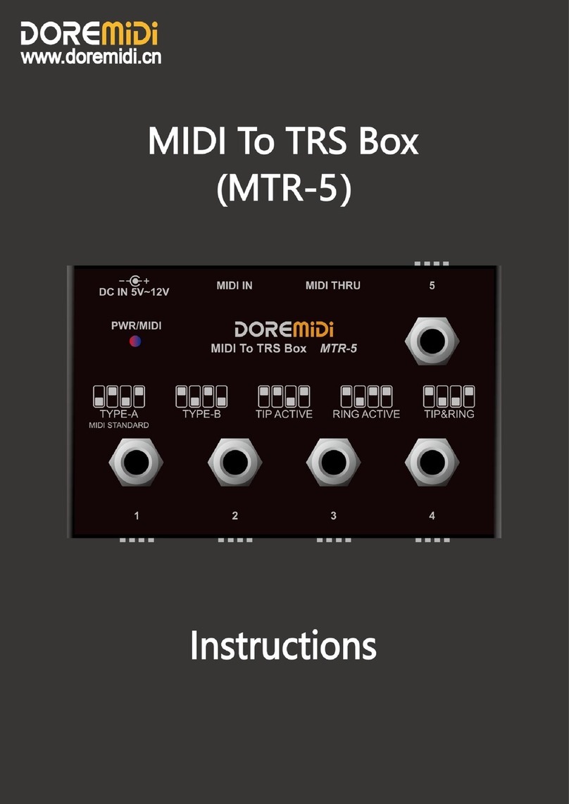
DOREMIDI MIDI To TRS Box User manual

DOREMIDI

DOREMIDI MIDI To TRS Box User manual

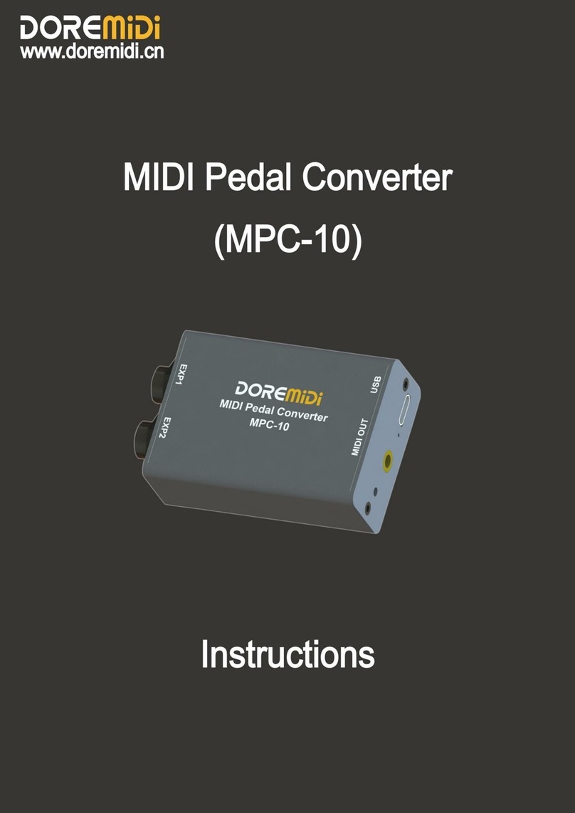
DOREMIDI MPC-10 User manual

DOREMIDI

DOREMIDI MPC-10 User manual

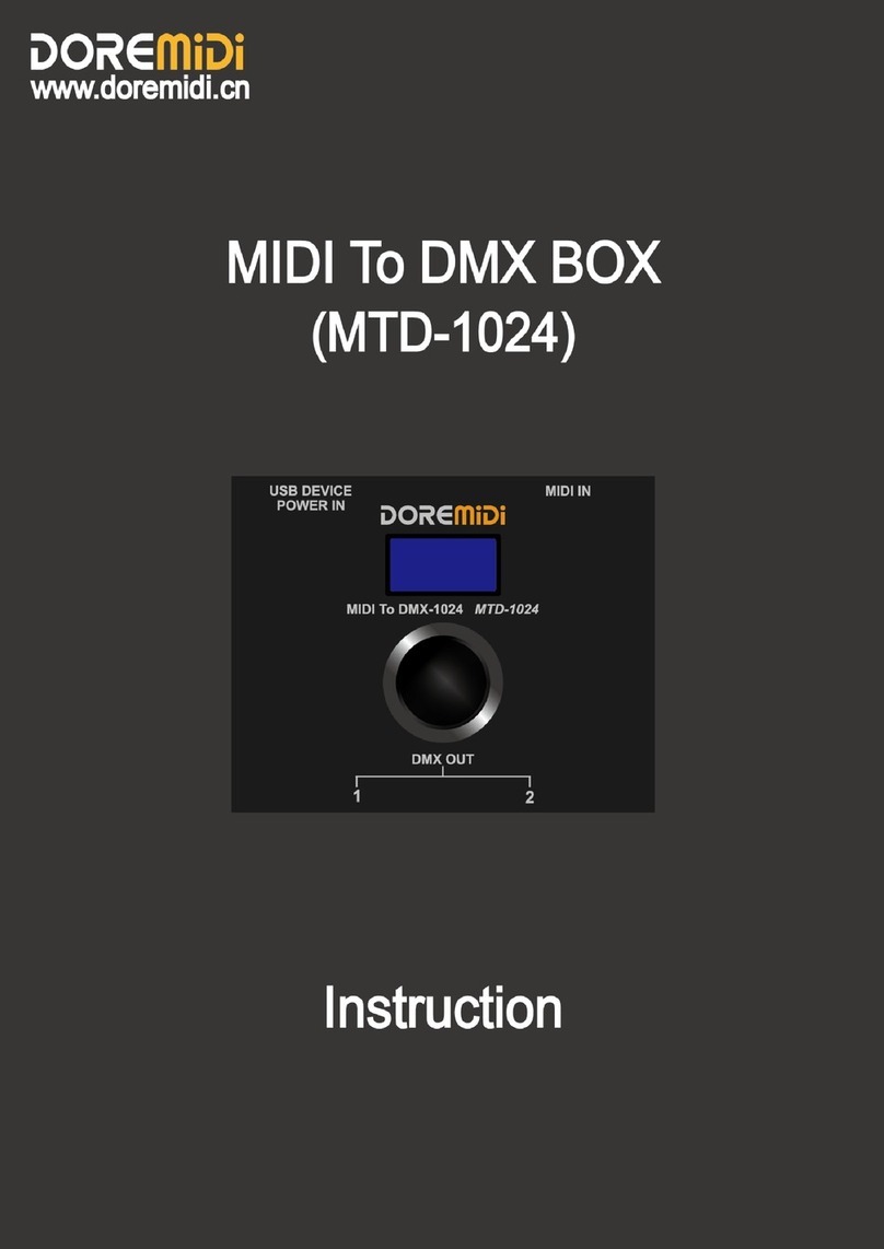
DOREMIDI MTD-1024 User manual

DOREMIDI

DOREMIDI MTD-1024 User manual

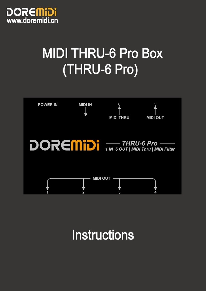
DOREMIDI MIDl THRU-6 Pro Box User manual

DOREMIDI

DOREMIDI MIDl THRU-6 Pro Box User manual

DOREMIDI MPC-10 User manual

DOREMIDI

DOREMIDI MPC-10 User manual

Popular Media Converter manuals by other brands

red lion GCM422 Bulletin

red lion

red lion GCM422 Bulletin

HIK VISION DS-6300DI-JX Series user manual

HIK VISION

HIK VISION DS-6300DI-JX Series user manual

TracoPower TMR 3 Series Application note

TracoPower

TracoPower TMR 3 Series Application note

PureLink PT-C-HDSDI user manual

PureLink

PureLink PT-C-HDSDI user manual

Iron logic Z-397 user manual

Iron logic

Iron logic Z-397 user manual

Black Box LME020A user manual

Black Box

Black Box LME020A user manual

Medel SAMBA 2 GO user manual

Medel

Medel SAMBA 2 GO user manual

Delta VF-MD Short manual

Delta

Delta VF-MD Short manual

Phase Technologies Phase Perfect PT007 Operation & installation manual

Phase Technologies

Phase Technologies Phase Perfect PT007 Operation & installation manual

Black Box VGA-Video Ultimate AC334A quick start guide

Black Box

Black Box VGA-Video Ultimate AC334A quick start guide

Black Box LGC5134A-R3 installation guide

Black Box

Black Box LGC5134A-R3 installation guide

Siemens SINAMICS DCM Compact User Manual

Siemens

Siemens SINAMICS DCM Compact User Manual

Avonic AV-CAP100 user manual

Avonic

Avonic AV-CAP100 user manual

ICP DAS USA ZT-USBC user manual

ICP DAS USA

ICP DAS USA ZT-USBC user manual

APS FC205 Operation manual

APS

APS FC205 Operation manual

CYP CSLUX-300 Operation manual

CYP

CYP CSLUX-300 Operation manual

Cablematic VD047 user manual

Cablematic

Cablematic VD047 user manual

SPL Diamond quick start

SPL

SPL Diamond quick start

manuals.online logo
manuals.online logoBrands
  • About & Mission
  • Contact us
  • Privacy Policy
  • Terms and Conditions

Copyright 2025 Manuals.Online. All Rights Reserved.