INSTALLINSTRUCTIONS:POWERSEATTRACK
924-073
Disclaimer:
Even though every attempt is made to ensure this information is complete and accurate, it is impossible to account for all possible circumstances or situations. Please consult with a qualied auto technician
before attempting to perform any work you are not qualied to do. Automobiles can be hazardous to work on; be sure to take all necessary safety precautions. Failure to do so may result in property damage
or personal injury. Certain motor vehicle standards and performance requirements may apply to your motor vehicle (such as Federal Motor Vehicle Safety Standards by the National Highway Trac Safety
Administration). Be sure that your work is performed in accordance with such standards and that you do not disable any motor vehicle safety feature.
ATTENTION: Refer to the appropriate shop manual for your vehicle to obtain specic service procedures for this part. If you do not have
a service manual or lack the skill to install this part, it is recommended that you seek the services of a qualied technician. Pay special
attention to all cautions and warnings included in the shop manual. Read and follow all instructions carefully.
4
©2012 Dorman Products, Inc.
No reproductions in whole or in part without prior written approval.
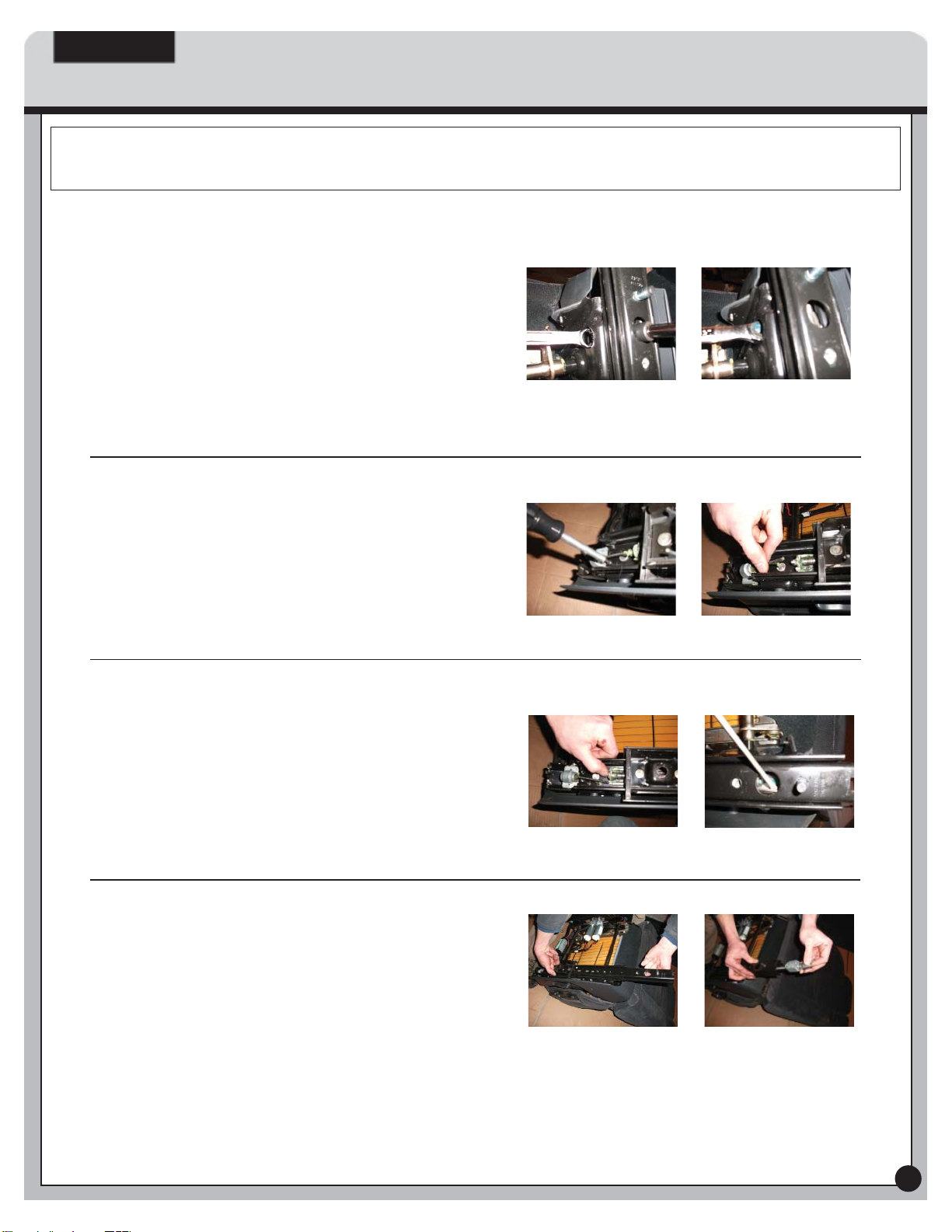
STEP 12: Shown above is the removed screw
and block assembly. You can now see why it was
necessary to have the seat all the way forward so
the block assembly is tight against the end of the
screw assembly to allow perfect alignment upon re-
installing block assembly. Wiggling block assembly
back and forth you should now also be able to see
where that back and forth seat movement was
coming from. The rubber bushing degrades with
time and allows the free movement of the block
assembly. Utilizing this repair kit, the special nylon
will not fail as the original rubber has as shown
above. Thread aluminum block assembly all the way
o of lead screw and then remove remaining rubber
bushing as well as threaded steel block nut, and
clean all parts thoroughly.
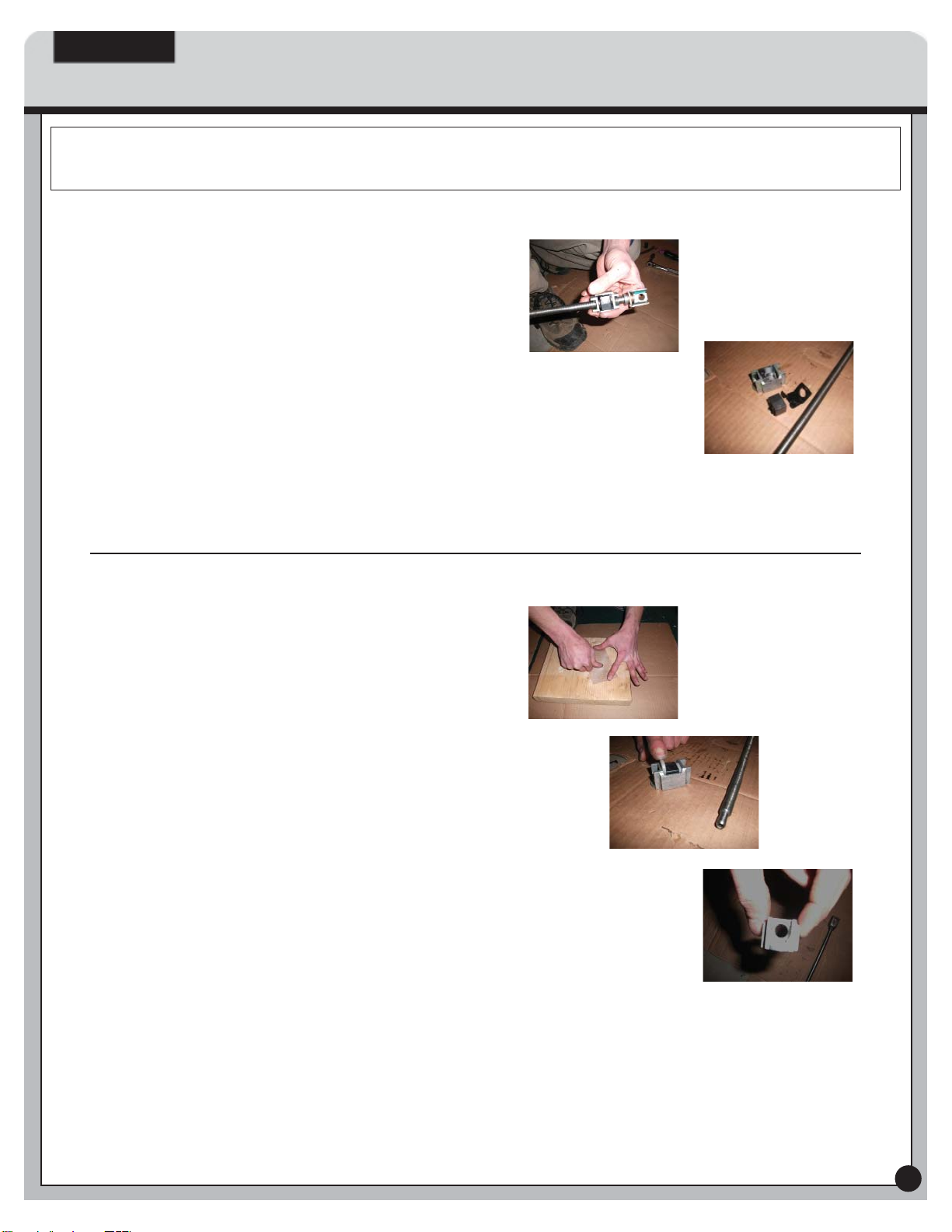
STEP 13: Now take the machined special nylon
washers and insert them in block as shown above
with one at side down and one at side visible (the
only side visible when the washers are installed in
the block, also noting that the “peak“ on the steel
nut should be up and visible). They will be a snug
t, use the screwdriver as a punch and very lightly
tap them in with the hammer if needed, you want
these to have a tight, zero clearance t. If unable
to insert them with light force, sand the face down
slightly with the sandpaper constantly checking
your progress to maintain a zero clearance t
between the steel block nut and aluminum housing
(you shouldn’t have to as they are machined within
.004“). When you get the washers seated in the
block, look through center of block assembly to
ensure the hole through the center of the washers
are aligned with the hole in the threaded steel block
and the top at of the washers are ush or slightly
below the ridge of the aluminum block assembly.
If not, try pushing the washers in further or pulling
them slightly up to align the holes and assure a
ush t with the aluminum block assembly.