Dorner Mfg. Corp. 2 851-728 Rev. A
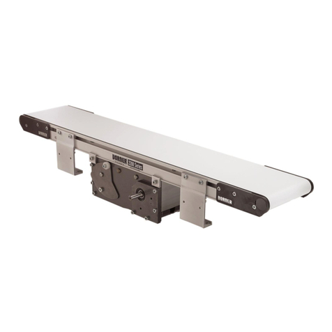
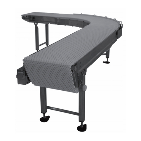
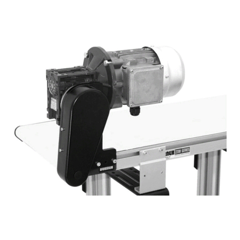
2200 and 2300 Series Modular Belt iDrive Conveyors
Table of Contents
Introduction ......................................................................... 2
Warnings -General Safety ................................................. 3
Product Description ............................................................. 4
Specifications ...................................................................... 4
Models ............................................................................. 4
iDrive Conveyors ......................................................... 4
CE Specifications........................................................... 4
Conveyor Supports: ......................................................... 5
Maximum Distances..................................................... 5
Specifications................................................................... 5
Motor Specifications........................................................ 5
iDrive Load Capacity (lbs) .............................................. 6
Installation ........................................................................... 7
Required Tools................................................................. 7
Recommended Installation Sequence .............................. 7
Conveyors Up to 10 ft (3048 mm)................................... 7
Conveyors Longer Than
10 ft (3048 mm) ............................................................... 7
2200 Series Mounting Brackets....................................... 8
2300 Series Mounting Brackets....................................... 8
Installing Plastic Belt ....................................................... 9
Proper Methods of Attachment
to Side Rails (2300 Series Only).................................... 10
Self-Drilling Screws ................................................... 10
Pre-Drill for Standard Screws .................................... 11
Guiding (2300 Series Only) ........................................... 12
Wiring ............................................................................ 12
Cover Mounted Controls
with 115 volt Power Supply ....................................... 12
Cover Mounted Controls
with Customer Provided Power Supply ..................... 13
Cover Mounted Controls ............................................ 13
Cover Mounted Controls
with Remote Start/Stop Cable .................................... 13
Cover Mounted Controls with Photo Eye Option ...... 14
Customer Wired Controls with Flying Leads ............ 15
Preventive Maintenance and Adjustment .......................... 16
Required Tools............................................................... 16
Standard Tools............................................................ 16
Special Tools .............................................................. 16
Checklist ........................................................................ 16
Lubrication..................................................................... 16
Maintaining Conveyor Belt ........................................... 16
Troubleshooting .......................................................... 16
Cleaning ...................................................................... 16
Conveyor Belt Replacement........................................... 16
Conveyor Belt Replacement Sequence....................... 16
Belt Removal .............................................................. 16
Belt Installation........................................................... 17
Conveyor Belt Tension................................................... 18
Removal of Belt Links ................................................ 18
Pulley and Sprocket Removal ........................................ 19
iDrive Tail................................................................... 19
Bearing Removal & Replacement .................................. 21
Removal ...................................................................... 21
Replacement................................................................ 22
Drive Spindle Installation............................................... 23
Idler End Wear Items ..................................................... 24
A - Standard Idler Tail ................................................ 24
B - Nose Bar Idler Tail ............................................... 25
Upper Wear Strip Replacement...................................... 26
Lower Wear Strip Replacement ..................................... 27
Motor Removal and Replacement .................................. 27
Notes .................................................................................. 29
Service Parts....................................................................... 30
Drive End ....................................................................... 30
Idler End ......................................................................... 32
Nose Bar Idler End ......................................................... 33
2200 Series Frame Assembly ......................................... 34
2300 Series Frame Assembly ......................................... 35
Connecting Assembly without Stand Mounts ................ 36
Connecting Assembly with Mounting Brackets............. 36
Return Wear Strip........................................................... 37
-01 Low Side .................................................................. 38
-04 3” (76 mm) Aluminum Side.................................... 39
-05 1.5” (38 mm) Aluminum Side................................. 40
-09 Low to High Side .................................................... 41
-13 Adjustable Guiding ................................................. 42
-14 Tool-Less Adjustable Guiding ................................ 43
Flared Side Guiding........................................................ 44
Mounting Brackets ......................................................... 45
Mounting Brackets for 2’ (610 mm) Conveyors ............ 45
Photo Eye ....................................................................... 46
Conveyor Belting ........................................................... 46
Belting Per Foot (305 mm) ......................................... 46
Notes .................................................................................. 47
Return Policy...................................................................... 48
Introduction
Upon receipt of shipment:
• Compare shipment with packing slip. Contact factory
regarding discrepancies.
• Inspect packages for shipping damage. Contact carrier
regarding damage.
• Accessories may be shipped loose. See accessory instruc-
tions for installation.
Dorner’s Limited Warranty applies.
Dorner has convenient, pre-configured kits of Key Service
Parts for all conveyor products. These time saving kits are
easy to order, designed for fast installation, and guarantee
you will have what you need when you need it. Key Parts
and Kits are marked in the Service Parts section of this
manual with the Performance Parts Kits logo .
Dorner 2200 & 2300 series conveyors are covered by Patent
Numbers 5,174,435, 6,298,981, 6,422,382 and
corresponding patents and patent applications in other
countries.
Dorner reserves the right to make changes at any time
without notice or obligation.
Some illustrations may show guards
removed. DO NOT operate equipment
without guards.

