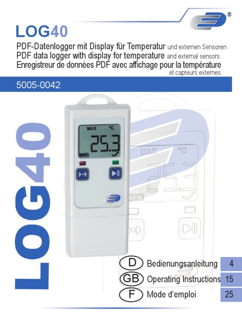
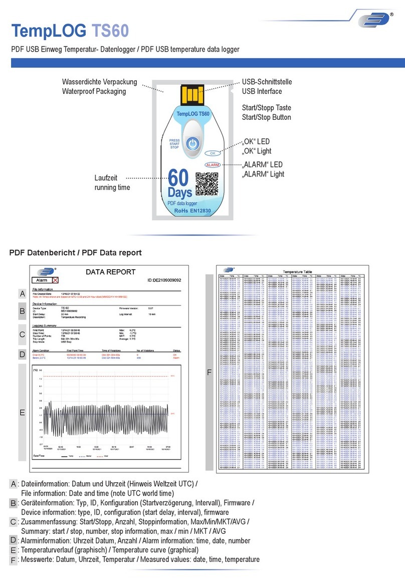
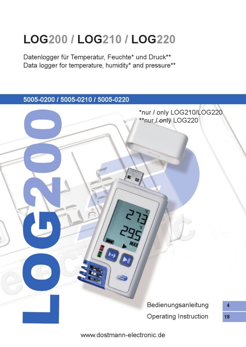
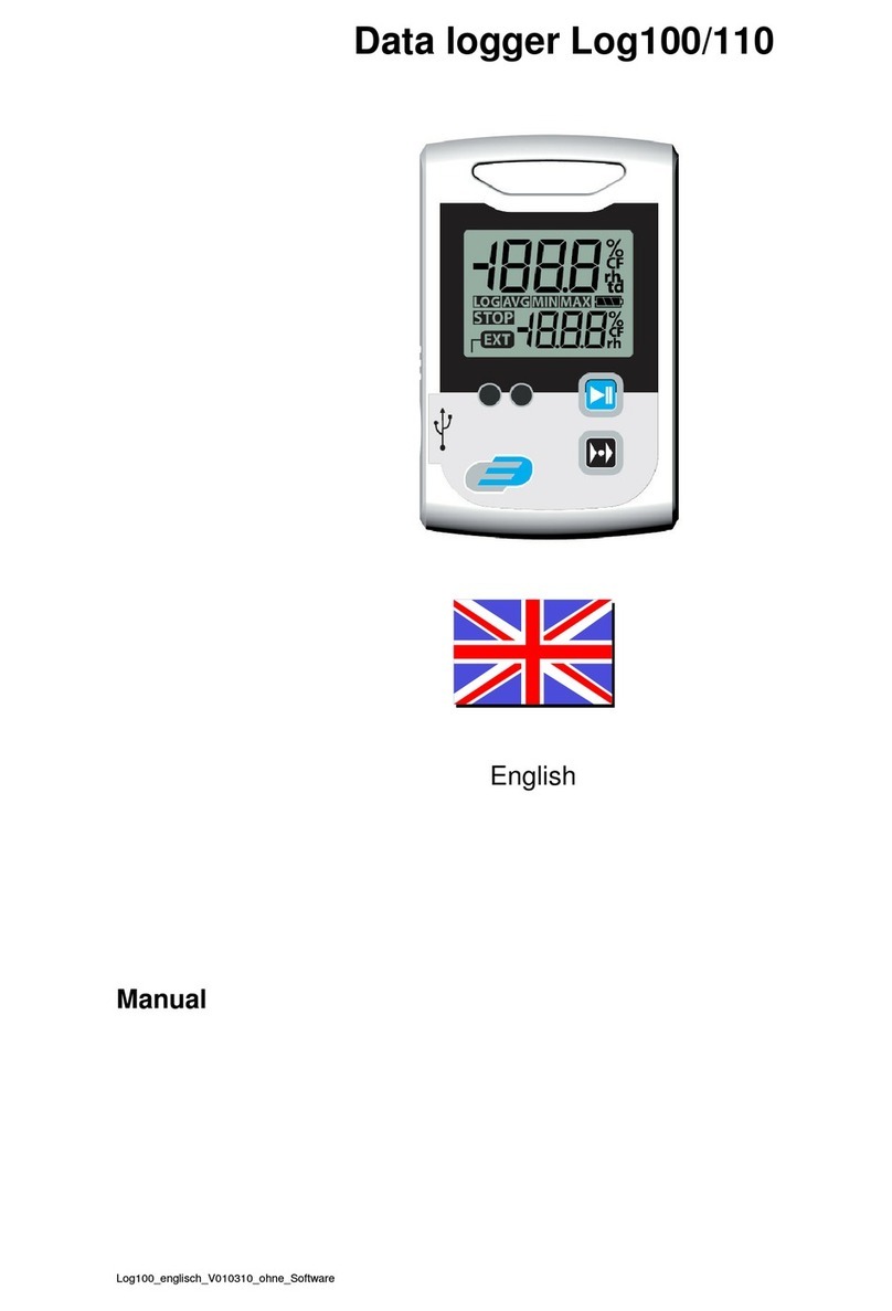
Dostmann Electronic LOG200 Series User manual

LOG 200 / LOG 210 / LOG 220 / LOG 200 TC / LOG 200 / LOG 210 / LOG 220 / LOG 200 TC / LOG 200 / LOG 210 / LOG 220 / LOG 200 TC / LOG 200 / LOG 210 / LOG 220 / LOG 200 TC / LOG 200 / LOG 210 / LOG 220 / LOG 200 TC / LOG 200 / LOG 210 / LOG 220 / LOG 200 TC / LOG 200 / LOG 210 / LOG 220 / LOG 200 TC / LOG 200 / LOG 210 / LOG 220 / LOG 200 TC /
LOG 210 TC / LOG 200 E / LOG 220 ELOG 210 TC / LOG 200 E / LOG 220 ELOG 210 TC / LOG 200 E / LOG 220 ELOG 210 TC / LOG 200 E / LOG 220 ELOG 210 TC / LOG 200 E / LOG 220 ELOG 210 TC / LOG 200 E / LOG 220 E
PDF data logger for temperature, humidity *, pressure ** and CO 2 ***PDF data logger for temperature, humidity *, pressure ** and CO 2 ***
PDF Data logs for temperature, humidity *, pressure ** and CO 2 ***PDF Data logs for temperature, humidity *, pressure ** and CO 2 ***
PDF Registrar of Température, Humidity *, Pressure ** and CO 2 ***PDF Registrar of Température, Humidity *, Pressure ** and CO 2 ***
5005-0200 / 5005-0210 / 5005-0220 / 5005-0204 / 5005-0214 / 5005-0202 / 5005-0222
Operating Instructions 4
Operating Instruction 18
Mode d'emploi 31
*only / only / uniquement LOG210 / LOG220 /
LOG210 TC / LOG220 E
**only / only / unique LOG220 / LOG220 E
*** only / only / unique LOG220 E
www.dostmann-electronic.de

32
FIG. B
2
3
4
5
6
FIG. A
1
3
4
5
8
7
6
9
1
FIG. C
LOG220_16099908_2016-09-27T103123.PDF LOG220 SN 16099908 V 04.00
Test FW 4.00 Beta
20.10.2016
TEST LOG220
Configuration / ConfigurationConfiguration / ConfigurationConfiguration / Configuration
User / Operator User / Operator User / Operator WD
Interval / Interval Interval / Interval Interval / Interval 00:00:30
Start possible / Start possible by Start possible / Start possible by Start possible / Start possible by Taste / ButtonTaste / ButtonTaste / Button
Starting delay / Start delay Starting delay / Start delay Starting delay / Start delay 00:00:00
Stop possible / Stop possible by Stop possible / Stop possible by Stop possible / Stop possible by USB connection / USB connectUSB connection / USB connectUSB connection / USB connect
Alarm delay / Alarm delay Alarm delay / Alarm delay Alarm delay / Alarm delay 00:00:00 Alarm below / Alarm low 00:00:00 Alarm below / Alarm low 00:00:00 Alarm below / Alarm low
Alarm above / Alarm highAlarm above / Alarm highAlarm above / Alarm high
Temperature / Temperature Temperature / Temperature Temperature / Temperature 20.0 ° C 30.0 ° C
Humidity / Humidity Humidity / Humidity Humidity / Humidity 4.0% rH 70.0% rH
Rel. Air pressure / Rel. air pressureRel. Air pressure / Rel. air pressureRel. Air pressure / Rel. air pressure 990.0 hPa 1030.0 hPa
Summary Summary / SummarySummary Summary / SummarySummary Summary / Summary
Start time / Start time Start time / Start time Start time / Start time 27.09.2016 10:31:27 Start by / Start by Start by / Start by Start by / Start by Taste / ButtonTaste / ButtonTaste / Button
Stop time / Stop time Stop time / Stop time Stop time / Stop time 27.09.2016 12:43:27 Stop by / Stop by Stop by / Stop by Stop by / Stop by USB connection / USB connectUSB connection / USB connectUSB connection / USB connect
Data sets / Records Data sets / Records Data sets / Records 265 Duration / Duration Duration / Duration Duration / Duration 02:12:00
Min Avg Max Höhe ü.dN / Altitude ASLHöhe ü.dN / Altitude ASLHöhe ü.dN / Altitude ASL
Dew Point / Dew point Dew Point / Dew point Dew Point / Dew point 13.9 ° C 14.1 ° C 16.2 ° C
Temperature / Temperature Temperature / Temperature Temperature / Temperature 23.6 ° C 25.1 ° C 26.3 ° C
Humidity / Humidity Humidity / Humidity Humidity / Humidity 49.9% rH 50.7% rH 55.9% rH
Rel. Air pressure / Rel. air pressureRel. Air pressure / Rel. air pressureRel. Air pressure / Rel. air pressure 1004.9 hPa 1005.0 hPa 1005.3 hPa 162 m
Count / CountCount / CountCount / Count
Alarm / Alarm Alarm / Alarm Alarm / Alarm 0
Rel. Air pressure / Rel. air pressureRel. Air pressure / Rel. air pressureRel. Air pressure / Rel. air pressure Humidity / Humidity Humidity / Humidity Humidity / Humidity Temperature / TemperatureTemperature / TemperatureTemperature / Temperature
Dew Point / Dew point Dew Point / Dew point Dew Point / Dew point Motion sensor / Move sensor Motion sensor / Move sensor Motion sensor / Move sensor Marking / MarkMarking / MarkMarking / Mark
MOV 0
27.09.2016
10:31:27
27.09.2016
11:01:27
27.09.2016
11:31:27
27.09.2016
12:01:27
27.09.2016
12:31:27
27.09.2016
13:01:27
10.0 ° C
15.0 ° C
20.0 ° C
25.0 ° C
30.0 ° C
47.5% rH
50.0% rH
52.5% rH
55.0% rH
57.5% rH
1004.0 hPa
1004.5 hPa
1005.0 hPa
1005.5 hPa
1006.0 hPa
Signature / SignatureSignature / SignatureSignature / Signature
*
*
* *
*only LOG210 / LOG220
** only LOG220
B
C
D
E
G
H
A
F
2
10
11

54
Table of contents
1. Introduction1. Introduction 5
2. Hints / Safety notes / Please note2. Hints / Safety notes / Please note 5
3. Scope of delivery3. Scope of delivery 5
4. Delivery scope and use4. Delivery scope and use 5
5. Operation of the device5. Operation of the device
5.1 Device description 6
5.2 Operation of the device 7
5.2.1 Default setting on extradition 7
5.2.1.1 Power Save Mode for Display 8
5.2.2 Windows Software for LOG200 Series 8
5.2.2.1 Log Connect Configuration Software 8
5.3 First start & record start 8
5.3.1 Restart Recording 9
5.3.2 Memory used (%), date, time displayed 10
5.4 Stop recording / PDF output 10
5.4.1 Stop recording via key or time point 10
5.5 PDF Statement (Fig. C) 11
5.6 USB connection 11
5.7 Mode key: EXT, AVG, MIN, MAX 12
5.7.1 The Special Function of the Mode Key 12
5.7.1.1 Inserting Markers 12
5.7.1.2 Removing the MAX-MIN display memory 12
5.8 Battery change / battery status indicator 13
5.8.1 Set date / time after battery change by keyboard 14
5.9 Alarm signals 14
6. Technical data 6.1 Safety information 6. Technical data 6.1 Safety information 6. Technical data 6.1 Safety information 15
7. General provisions7. General provisions
Statement of signs 16
8. Disposal8. Disposal 16
9 Labeling9 Labeling 16
10. Storage & cleaning10. Storage & cleaning 16
1. Introduction
Very good customer, very good customer,
heartfelt thanks for buying these products. Before commissioning, please read the operating
instructions carefully. That way, you get valuable information and become familiar with the
measuring device.
2. Note / Please note
•The contents of the packaging can be checked for insecurity and completeness.
•Remove the protective film over the display.
•To clean the instrument, do not use an aggressive cleaning agent, but only with a
dry or damp cloth. There is no liquid in the interior of the dish.
•Store the measuring instrument in a dry and clean place.
•Avoid violent effects such as size or pressure.
•For no correct or incomplete measurements and no consequences, no gun exists.
The liability for consequential consequential damages is excluded.
•Do not use the device in explosion-hazardous areas. Lebensgefahr!
•Do not bring the device in an environment that is hotter than 85 ° C. Lithium Battery
Explosion Hazard!
•Turn off the device with no microwave radiation. Lithium Battery Explosion Hazard!
3. Scope of delivery
• Data loggers
• Wall bracket
4. Scope of delivery and use
The measuring devices of the LOG200 series are for recording, alarm, visualization of
temperature, humidity *, dew point *. Pressure measurement values ** and CO 2 *** (* only LOG210 / temperature, humidity *, dew point *. Pressure measurement values ** and CO 2 *** (* only LOG210 / temperature, humidity *, dew point *. Pressure measurement values ** and CO 2 *** (* only LOG210 /
220, ** only LOG220, *** only LOG220 E) suitable. LOG200 TC and LOG210 TC have 2 external
inputs for thermocouples. LOG200 E and LOG220 E have an external sensor input for
temperature sensors or CO 2+ Humidity sensor (only LOG220 E). Areas of focus are the monitoring temperature sensors or CO 2+ Humidity sensor (only LOG220 E). Areas of focus are the monitoring temperature sensors or CO 2+ Humidity sensor (only LOG220 E). Areas of focus are the monitoring
of storage and transport conditions or other temperature-, humidity- and / or pressure-sensitive
processes. LOG210 TC is additionally suitable for sensing wall molding. The logger has a direct
USB connection and can be connected to any cable on any Windows PC, Apple computer or
tablet (ggfalls with USB adapter).
•Battery 3.6 Volt (prepared individually)
•USB cover, 2x Thermocouple Type K (only TC)
• 2x Screws and Double

76
5. Operation of the device
5.1 Device description
5.2 Installation of the device
NOTICE!
Please note our battery recommendation only: Use only the manufacturer's battery
NOTICE!
Please note our battery recommendation only: Use only the manufacturer's battery
type SAFT LS 14250 3.6 Volt or DYNAMIS Lithium Battery. LI-110 1/2 AA / S respectively. vom
Manufacturer release type Battery type. To commission, remove the logger from its packaging
and remove the display protective film. The logger is ready to be programmed and ready for
delivery. It can be used without software!
Before starting operation, the data logger will indicate for 2 seconds FS (Factory
setting) in motion or key press and then the current measurement values will be
displayed for 2 minutes, then the display will switch off. Moving or key presses the
measuring device again for 2 minutes in the described mode.
The display shows the current measurement values, extremes and average values per
measurement size. In the status bar, information is displayed for battery status, recording mode and
alarms. The green LED flashes during recording every 30 seconds. The red LED serves as an
indicator of border alarms. The logger also had an internal buzzer (beep tone) that supports the
operator's management and is used for alarms.
The product is suitable only for the above described range. Do not use the product
otherwise, as provided in this manual. No proper repair, alteration or modification of
the device is required.
FIG. A ( see page 2)FIG. A ( see page 2)
1. USB protective cap
2. USB connection
3. LCD display see FIG. B
4. LED: red / green
5. Sensor compartment
(Position of Sensors)
6. Battery compartment
7. Fashion key
8. Start / Stop key
9. closable wall mount
10. External connectors (only TC)
11. External connector (only E)
FIG. B ( see page 2)FIG. B ( see page 2)
1. Units in Measurement Value Line 1
2. Measurement value Line 1
3. Units in Measurement Value Line 2
4. Measured value line 2
5. Extreme sail
EXT = external sensor (only TC) AVG =
average value, MIN = minimum value,
MAX = maximum value
(no symbol) = current measurement value
6. Status bar (left to right): Battery
display, USB connection display,
Logger started, Logger configured,
iO, (without ► symbol) and
alarm not found iO (without ►
symbol)
5.2.1 Default setting on extradition
The default parameters are entered as default. With the LogConnect * software you can change the
parameters of your wishes accordingly. Memory Interval:
5 minutes LOG210 / LOG220, / LOG200 TC / LOG210 TC / LOG220 E 15
minutes LOG200 / LOG200 E
Measurement interval: during the data recording, the measurement interval corresponds
to the storage interval (If the logger is not started, the logger
should be measured for 15 minutes at a 6 second rate, then for 24
hours at 15 minute rate, then measured at the hourly rate.
measured in 6-second clock.
Start possible by: Taste
Stop possible by: USB connection
Alarm: out of
Alarm delay: 0 s
Display values in the display: in the
Display Power Save Mode: in the
Should the display (via Software Log Connect) be deactivated, only the battery symbol, the symbol logger
started (►) and / or logger configured (II) will be displayed in the status display.

98
5.3 First Start & Record Start
Key 2 sec. Holds, current date used and time of loggers
as well as signal tone for approx. 2 seconds.
LED illuminates approx. 2 seconds green.
Logger has been started.
To change the configuration, the software LogConnect * is needed.
*Download the free LogConnect Software: www.dostmann / electronic.de -> Downloads -> Software / <Your
Logger> / Software / LogConnect_XXX.zip (Choose the latest version of XXX) Display of displays in
Auto-Mode (In Auto-Mode the switch Display automatically by possible measurement sizes or LOG200:
MAX / MIN values)
5.3.1 Restart Recording
See 5.3 Starting and recording first. In the default setting, the logger is started via the Start /
Stop button at the push of a button and is stopped via USB connection. These values were
automatically graphically represented in PDF.
NOTICE!
When you start again, the existing PDF file will be overwritten.
Important!
Secure the extracted PDF files on your PC. If you open LogConnect when you connect
Important!
Secure the extracted PDF files on your PC. If you open LogConnect when you connect
the loggers to the PC and activate AutoSave (default), this automatically saves the measurement
data.
5.2.2 Windows Software for LOG200 Series
The LOG200 series data loggers are pre-programmed and can be installed without any software!
It still provides a free software that can be downloaded directly from the following website:
See 5.2.2.1 LogConnect configuration software
5.2.2.1 LogConnect Configuration Software
With this software, configuration parameters can be changed or changed. be created. For example:
measurement interval, alarm limit values, start parameters (eg at a fixed time point, set / correct time,
deactivate the display… etc.) One online direct aid in operation! Download the free LogConnect Software:
www.dostmann / electronic.de -> Downloads -> Software / <Your Logger> / Software /
LogConnect_XXX.zip (choose XXX latest version)
5.2.1.1 Power Save Mode for Display
On delivery, the power save mode is activated. The display switches off automatically after 2 minutes.
In the background, the data logger remains active. It will be measured and / or stored according to
condition. The internal clock runs. Moving the loggers will activate the display again.
LOG200 LOG210
LOG220
LED flashes every 30 seconds
Loggers with external inputs
only recorded sensors that
were plugged in at start-up.

1110
5.5 PDF Statement (Fig. C)
Filename: eg
LOG220_16099908_2016-09-27T103123.PDF LOG220:
Dish
16099908: Serial no.
2016-09-27: Begin recording (date)
T103123: Time: HHMMSS
Description: can only be described with the LogConnect *
software.
Configuration: preset parameters
Summary: Overview of knife results
Graphics: Visual representation of the measurement values
PURPLE: Tells when whether Logger is moving
Signature: In case of need to understand PDFs.
: Measurement OK : Measurement is not in order
X
A
B
C
D
E
F
G
H
5.4 Stop recording / erase PDF (default setting)
Connect loggers with USB interface. Signalton
pours for approx. 1Sec.
LED blinks green until the PDF is displayed (can take up to 40
seconds).
The symbol ► in the status bar is not displayed anymore. The
logger has stopped! Signal tone is on and LED lights green.
Logger is displayed as a changeover data carrier LOG200 /
LOG210 / LOG220 / LOG200 TC / LOG210 TC / LOG200 E /
LOG220 E.
Open and secure PDF.
PDF will be overwritten at the next
launch!
NOTICE!
At the logger-start, the Extreme (Max- and Min-Value), as well as the average
NOTICE!
At the logger-start, the Extreme (Max- and Min-Value), as well as the average
value, were reset! 5.6 USB connection
To configure or evaluate the data loggers, the data logger must be connected to the USB
connection of your PCs. For configuration read the corresponding section in the manual
or in the help text of the LogConnect software.
*Download the free LogConnect Software: www.dostmann / electronic.de -> Downloads ->
Software / <Your Logger> / Software / LogConnect_XXX.zip (choose XXX latest version)
5.3.2 Memory used (%), date, time displayed
By briefly pressing the start key (after logger
start), it will be in row 1 MEM and in row 2 in
percent of the previously stored memory for
2 sec. display, then the image changes and
it is displayed for 2 sec. Date and time
displayed.
5.4.1 Stop recording via key or time point
is customizable via Software LogConnect.
In the corresponding setting, the Start key is also the Stop key.

1312
5.7.1 The Special Function of the Mode Key
5.7.1.1 Inserting Markers
At particular events during the recording to hold, the sex
Brands are set. To place a marker (marker) in the graphics of the PDFs, the mode key
must be held for 2.5 seconds (see marker on the PDF image Fig.C). The successful
marking is confirmed by a short signal tone. The marking will then be stored with the next
measurement (note the interval).
5.7.1.2 Removing the MAX-MIN display memory
The logger has a MIN / MAX function for holding the extreme values over a given time frame. Press and
hold the MODE key for 5 seconds until a small tune is reached. Damit is reset to the measurement period.
They can, for example, capture the highest / lowest daytime temperatures. Die MIN / MAX Function works
independently of Log operation.
Please note:
-At the start of recording, the MIN / MAX memory is reset to indicate the MIN / MAX / average
values appropriate for recording.
-During the recording, when setting the MIN / MAX / average values, a single mark
will be set.
5.7 Display modes and mode key: EXT, AVG, MIN, MAX
The first line shows the current measurement value of the main measurement
channels: LOG200: Temperature, LOG210: Humidity, LOG220: Air pressure,
LOG200 TC / LOG210 TC: External temperature 1, LOG200 E: Internal
temperature, LOG220 E: Air pressure
The display of the second row depends on the selected mode. There are two display modes:
1. AUTO MODE ( Preset for LOG200, LOG210, LOG220) - the second line alternates 1. AUTO MODE ( Preset for LOG200, LOG210, LOG220) - the second line alternates
every 3 seconds :: LOG200:
Minimum (MIN) / Maximum (MAX) / Average (AVG) LOG210:
Temperature and Dew Point (Td)
LOG220: Humidity, temperature and dew point LOG200 TC: Internal
temperature and external temperature 2
LOG210 TC: Internal Temperature, Internal Humidity, Internal Dew Point, External Temperature 2 LOG200 E:
Current Temperature / Minimum (MIN) / Maximum (MAX) / Average
(AVG) temperature (external) and minimum (MIN) / maximum (MAX) / average
(AVG) temperature (internal)
LOG220 E: Current measurement values of external connected sensors / current measurement values
internal measurement channels humidity, temperature, dew point You recognize the value in
the physical unit over the measurement value (° C / ° F = temperature, Td + ° C / ° F = dew point,% rH =
humidity, hPa = pressure, ppm = CO 2)humidity, hPa = pressure, ppm = CO 2)
as well as the additional symbols <no symbol> = current measurement value, MIN = minimum, MAX =
maximum, AVG = average, EXT = external channel 2, EXT flashing = external channel 1.
The AUTO mode gives you an overview of the measurement values of all channels in a short
time. By pressing the MODE key (left key) they go from AUTO mode to manual mode:
2. MANUAL Mode ( Preset for LOG200 TC, LOG210 TC) - the MODE key flashes in the 2. MANUAL Mode ( Preset for LOG200 TC, LOG210 TC) - the MODE key flashes in the
second row through all available measurement channels in the order of current
measurement value (no symbol), minimum (MIN), maximum (MAX), average (AVG).
Details:
-For the main mass channel in the upper row, only MIN, MAX, AVG are displayed.
-For LOG200 TC and LOG210 TC, MIN, MAX, AVG are indicated with a flashing EXT for
the external sensor 1 (main channel) and a standing EXT for the external sensor 2.
The manual mode allows the display of an optional measurement channel in addition to the main
measurement channel, for example, the maximum pressure for the current pressure. Press and hold the
MODE key until the display AUtO appears to return to AUTO Mode.

1514
5.9 Alarm signals in boundary overrides
Signal tone caught every 30 seconds. for 1 sec. and the LED
flashes red (3 sec.). Those boundary values were set via
Software LogConnect *. If a limit value is exceeded, an X will
appear in the right, lower display corner. Along with the
corresponding PDF print, the alarm is set-
if described and visible. Only by restarting the loggers will X be removed on display!
Logger not in recording mode
LED flashes every 4 sec. rot. Battery change. LED
blinks many red hardware errors!
*Download the free LogConnect Software: www.dostmann / electronic.de -> Downloads ->
Software / <Your Logger> / Software / LogConnect_XXX.zip (choose XXX latest version)
5.8.1 Set date / time to battery change by keyboard
After a battery change or a power failure, the device automatically goes into a special
mode for date / time / interval.
Can you correct the date? N =
No by pressing the Mode key,
the logger returns to Normal
mode. Or select Y = Yes by
pressing the start key, the
following sequence begins:
Mode key increases the respective value,
Start key confirms and jumps to the next
value. After date-time query, memory interval
(INT) can be changed.
N = No… acquires
setting Y = Yes,
new settings are
stored
→ → → →
...
NOTICE!
After the battery change, please check the clock (internal clock) and correct it if
NOTICE!
After the battery change, please check the clock (internal clock) and correct it if
necessary. See 5.2.2.1 Log Connect configuration software or 5.8.1 Set date / time after
battery change by keyboard
•The empty battery icon says that you have that battery in short
interchangeable mice. They can now about Carry out correct measurements for 10
hours.
•The battery symbol indicates up to 3 segments.
•If the battery symbol on the display is blinking then rich it
Battery charge is no longer available for measurements.
5.8 Battery change / battery status display
NOTICE!
Please note our battery recommendation only: Use only the manufacturer's battery
NOTICE!
Please note our battery recommendation only: Use only the manufacturer's battery
type SAFT LS 14250 3.6 Volt or DYNAMIS Lithium Battery. LI-110 1/2 AA / S respectively.
vom Manufacturer release type Battery type.
Turn the battery cover to the bottom 20 ° to the left, the
battery compartment opens.
Remove empty battery and new
battery was pictured.
Battery change OK: Both LEDs illuminate for approx. 1 sec. on
and one signal tone caught on.

1716
10. Storage & Cleaning
The device is stored at room temperature (10 ... 40 ° C). Cleaning Only use a soft
cotton cloth with water or medical alcohol.
Do not immerse the device in liquids.
8. Disposal
This product will be repaired using more valuable materials and components that can be
recycled and reused. Batteries and rechargeable batteries are not allowed in the garbage!
As a consumer you are
legally obligated, used batteries and rechargeable batteries for environmentally
friendly disposal during trade or appropriate collection according to national or
local regulations. The designations for contained heavy metals are: Cd =
Cadmium, Hg = Mercury, Pb = Lead
This device is in accordance with the EU directive on the disposal of electrical and
electronics devices (WEEE).
This product must not be disposed of with the household garbage. The user is
obliged to submit the Altgerät to the environmentally friendly disposal of a
selected facility for the disposal of electrical and electronics equipment.
9. Labeling only LOG2009. Labeling only LOG200
CE marking, EN 12830, EN 13485, Suitability for storage (S) and transport (T) for food and
distributor (C), accuracy class 1 (-30 .. + 70 ° C). In accordance with EN 13486, we recommend an
annual recalibration.
7. Sign Statement
With this sign, we confirm that the product meets the requirements set out in
the EC guidelines and is to examine the established test procedures.
6. Technical data
Temperature
Area of measurement: -+ 40 ° C
Resolution: 0.1 ° C
Air pressure only LOG220 / LOG220 EAir pressure only LOG220 / LOG220 E
Area of measurement: 300-1100hPa
Resolution: 0.1 hPa
Memory:
LOG200: 150,000 data sets (temperature and motion)
LOG210: 100,000 data sets (temperature, relative humidity, dew point and
motion)
LOG220: 60,000 data sets (temperature, relative humidity, pressure, dew point
and motion)
LOG200 TC: 60,000 data sets
(Temperature + 2 external thermocouples T1, T2 +
movement)
LOG210 TC: 60,000 data sets (humidity + temperature + dew point + 2 external
thermocouples T1, T2 + movement)
LOG200 E: 100,000 data sets (temperature and motion)
LOG220 E: 60,000 data sets (temperature, relative humidity, pressure, CO 260,000 data sets (temperature, relative humidity, pressure, CO 2
Dew Point and Movement)
Interface: USB (integral)
Measurements: 91.5 x 42 x 20 mm
Weight: approx. 83 g incl. Wall bracket
Battery: 1 x 3.6 Volt Lithium ½ AA
6.1 Safety information
•Keep the batteries and devices out of the reach of children.
•Batteries contain harmful acids and can be life-threatening if swallowed. If a battery
is swallowed, this can lead to severe internal damage and to death within 2 hours. If
you suspect a battery could be swallowed or otherwise in the body, seek medical
help immediately.
•Do not fire, short-circuit, recharge, or recharge batteries. Explosions danger!
Rel. Humidity only LOG210 / LOG220 / LOG210 TC / LOG220 ERel. Humidity only LOG210 / LOG220 / LOG210 TC / LOG220 E
Area of measurement: 0..100% rF
Resolution: 0.1% rF
CO 2 only LOG220 ECO 2 only LOG220 ECO 2 only LOG220 E
Area of measurement: 400-10000 ppm
Resolution: 1 ppm
•To avoid running out of batteries, weak batteries should be replaced quickly. Never
use old and new batteries or batteries of different types at the same time.
•Wear chemical-resistant protective gloves and goggles when handling
batteries that have run out!

1918
Index
1. Introduction 19
2. Kindly note / Safety Instructions2. Kindly note / Safety Instructions 19
3. Delivery contents3. Delivery contents 19
4. Equipment and usage4. Equipment and usage 19
5. How to use device5. How to use device
5.1 Device description 20
5.2 Device start-up 21
5.2.1 Factory settings 21
5.2.1.1 Power-Save Mode for Display 22
5.2.2 Windows Software for LOG200 Series 22
5.2.2.1 Log Software Configuration Software 22
5.3 First start / start recording 22
5.3.1 Restart recording 23
5.3.2 Display used memory (%), date and time 24
5.4 Stop recording / create PDF 24
5.4.1 Stop recording by button 24
5.5 Description of PDF result file (Fig. C) 25
5.6 USB Connection 25
5.7 Display Modes and Mode - Button: EXT, AVG, MIN, MAX 26
5.7.1 Special function of Mode Button 27
5.7.1.1. Set marker 27
5.7.1.2 Reset Max-Min Buffer 27
5.8 Battery replacement / Battery status indication 27
5.8.1 Set Date and Time after battery replacement via button 28
5.9 Alerts 28
6. Technical data 6.1 Risk of injury 6. Technical data 6.1 Risk of injury 6. Technical data 6.1 Risk of injury 29
7. Explanation of symbol7. Explanation of symbol 30
8. Waste disposal8. Waste disposal 30
9 Marking 9 Marking 30
10. Storage and cleaning 10. Storage and cleaning 30
1. Introduction
Dear Sir or Madam,
Thank you very much for purchasing one of our products. Before operating the data logger please
read this manual carefully. You will get useful information for understanding all functions.
2. Kindly note / Safety Instructions
• Check if the contents of the package is undamaged and complete.
•Remove the protection foil above the display.
•For cleaning the instrument please do not use an abrasive cleaner only a dry or moist piece of soft
cloth. Do not allow any liquid into the interior of the device.
•Please store the measuring instrument in a dry and clean place.
•Avoid any force like shocks or pressure to the instrument.
•No responsibility is taken for irregular or incomplete measurement values and their results, the liability
for subsequent damages is excluded!
•Do not use the device in explosive areas. Danger of death!
•Do not use the device in an environment hotter than 85 ° C! The lithium
battery may explode!
•Do not expose the unsit to microwave radiantion. The lithium battery may explode!
3. Delivery contents
• Data logging
• Wall holder
4. Equipment and usage
LOG200 / LOG210 / LOG220 series loggers are suitable for recording, alarm tracking and display of
temperature, humidity *, dew point temperature *, barometric ** and CO 2 *** (* only LOG210 / 220, ** temperature, humidity *, dew point temperature *, barometric ** and CO 2 *** (* only LOG210 / 220, ** temperature, humidity *, dew point temperature *, barometric ** and CO 2 *** (* only LOG210 / 220, **
only LOG220, *** only LOG220 E) measurements. LOG200 TC and LOG210 TC feature 2 external
inputs for thermocouples. The LOG200 E and LOG220 E feature one external
input for temperature or
CO 2+ Humidity probes (LOG220 E only). Areas of application include monitoring of storage and CO 2+ Humidity probes (LOG220 E only). Areas of application include monitoring of storage and CO 2+ Humidity probes (LOG220 E only). Areas of application include monitoring of storage and
transport conditions or other temperature, moisture and / or pressure-sensitive processes. LOG210
TC additionally supports wall mold detection. The logger has a built-in USB port and can be
connected without cables to all Windows PCs, Apple computers or tablets (USB adapter may be
required). The USB port is protected by a plastic cap. Beside the actual measurement result, the
display shows MIN-MAX and AVG measurements of each measurement
•Battery 3.6 Volt (already inserted)
•USB protective cap, 2 x thermocouple type K (TC only)
• 2x screws and dowels

2120
channel. The bottom status line shows battery capacity, logger mode and alarm status.
The green LED flashes every 30 seconds during recording.
The red LED is used to display limit alarms or status messages (battery change)
...etc.). The logger also has an internal buzzer that supports the user interface. This product is
exclusively intended for the field of application described above. It should only be used as described
within these instructions. Unauthorized repairs, modifications or changes to the product are prohibited
and void any warranty!
5. How to use device
5.1 Device description Fig. A ( see 5.1 Device description Fig. A ( see
page 2)
1. USB cover
2. USB connector
3. LCD display see Fig. B
4. LED: green / red
5. Sensor compartment
(position of the sensor)
6. Battery case
7. Mode button,
8. Start / Stop button
9. lockable wall holder
10. External probes (TC only)
11. External probe (E only)
If the display has been deactivated (display off via Software LogConnect), the battery symbol and the symbol for
recording (►) or configuration (II) are still active in Line 4 (status line).
FIG. B ( see page 2)FIG. B ( see page 2)
1. Units of measurement line 1
2. Measurement line 1
3. Units of measurement line 2
4. Measurement line 2
5. Line3 for indication and extreme
measurements
EXT * = external probe (only visible when
external probe is connected) * TC * AVG =
average value, Min = minimum value, Max =
maximum value
(no symbol) = current measurement value
5.2 Device start-up
ATTENTION!
Please observe our battery recommendation strictly. Use only battery type LS 14250
ATTENTION!
Please observe our battery recommendation strictly. Use only battery type LS 14250
3.6 volt from manufacturer SAFT or DYNAMIS Lithium Batt. LI-110 1/2 AA / S, respectively, only
batteries authorized by the manufacturer. For operation take out the instrument from the packaging,
remove the display foil. The logger is already preset and ready to start. It can be used immediately
without any software! By pressing any button or moving the instrument before first operation the
instrument displays FS (factory setting) for 2 seconds, afterwards measurements are displayed for 2
minutes. Then the instrument display switches off. Repeated key hit or movement reactivates the
display.
5.2.1 Factory settings
Note the following default settings of the data logger before first use. By using the LogConnect *
software, the setting parameter can easily be changed: Recording Interval:
5 min. LOG210 / LOG220, / LOG200 TC / LOG210 TC / LOG220 E 15
min. LOG200 / LOG200 E
Measuring interval: During recording the measurement interval and recording interval are the
same! If the logger has not started (NOT RECORDING) the measuring
interval is every 6 seconds for 15 minutes, afterwards the measuring interval
is every 15 min. for 24 hours, afterwards the measuring interval is once per
hour. If you press any button or move the device it will start again to measure
every 6 seconds.
Start possible by: Key press
Stop possible by: USB connect
Alarm: off
Alarm delay: 0 s
Show measurements on display: on
Power-Save mode for display: on
6. Line4 status line (from left to right): Battery
indication, USB connection indication,
Data logger is recording, Data logger has
been configured by LogConnect and is
waiting for action, Data logger has been
stopped and OK, (without
► Symbol) Data logger has
been stopped and X NOT OK
(eg Alarm level reached
(without ► Symbol)

2322
5.2.1.1 Power-Save Mode for Display
The Power-Save Modes is activated by default. The display switches off when for 2 minutes no
button has been pressed or the instrument has not moved. The logger is still active, only the display
is switched off. The internal clock runs. Moving the logger will reactivate the display.
5.2.2 Windows Software for Log200 Series
The instruments of series Log200 are already preset and ready for launch. It can be used without any
software! However, there is a Windows Application free for download. Please note the free-to-use link:
see below 5.2.2.1 Log Connect Configuration Software
5.2.2.1 Log Software Configuration Software
With this software, the user can change configuration parameters like measuring interval, start
delay (or other start parameter), creating alarm levels or changing the internal clock time. The
Software Log Connect contains an online help. Download free LogConnect software:
www.dostmann-electronic.de/home.html -> Downloads -> Software / <your logger> / Software /
LogConnect_XXX.zip (XXX choose latest version)
5.3 First start / start recording
Press button for 2 seconds, beeper sounds for 1 second,
the actual date and time will be displayed for 2 further
seconds.
LED lights green for 2 sconds - logging has started!
LED blinks green every 30 sec.
Display in Auto-Mode (Display shows all measurement channel in a 3 second sequence)
By using the LogConnect software, the presets can easily be changed.
*Download free LogConnect software:
www.dostmann-electronic.de/home.html -> Downloads -> Software / <your logger> / Software /
LogConnect_XXX.zip (XXX choose latest version)
5.3.1 Restart recording
See 5.3. First start / start recording. The logger is started by default by button and stopped by USB port
plug-in. The measured values are plotted automatically to the PDF file.
NOTE:
When you restart the existing PDF file is overwritten.
NOTE:
When you restart the existing PDF file is overwritten.
Important!
Always save the generated PDF files to your PC. If LogConnect is open when connecting
Important!
Always save the generated PDF files to your PC. If LogConnect is open when connecting
the loggers and AutoSave is selected in Settings (Default), the log results are copied to a backup
location immediately by default.
LOG 200 LOG 210
LOG 220
Loggers with external inputs only
record the sensors that are already
attached at the start of logging.

2524
5.5 Description of PDF result file (see Fig. C)
Filename: eg
LOG220_16099908_2016-09-27T103123.PDF LOG220:
Device
16099908: Serial
2016-09-27: Start of recording (date)
T103123: hour: HHMMSS
Description: Log run info, edit with LogConnect * software
Configuration: preset parameters
Summary: Overview of measurement results
Graphics: Diagram of measured values
PURPLE: Indicates whether instrument has been moved
(with date and time)
Signature: Sign PDF if required.
: Measurement OK : Measurement failed
X
A
B
C
D
E
F
G
H
5.4 Stop recording / create PDF
Connect logs two to a USB port. Beeper sounds for 1 second. LED
blinks green until result PDF is created (can take up to 40
seconds).
The symbol ► disappears in the status line. Now the logger is
stopped.
The Logger is shown as removable drive LOG200 / LOG210 /
LOG220 / LOG200 TC / LOG210 TC LOG200 E / LOG220 E
View PDF and save. PDF will be overwritten with next log start!
Note:
With the next recording the Extrema (Max and Min value), and the AVG value will be
Note:
With the next recording the Extrema (Max and Min value), and the AVG value will be
reset.
5.3.2 Display used memory (%), date and time
After pressing the start button while the logger is
recording, the first line shows MEM and the second line
(line 2) displays the used memory percentage (%).
Afterwards the logger displays date and time for 2
seconds.
5.4.1 Stop recording by button.
To stop the Logger via button it is necessary to change the configuration by Software LogConnect. If this
setting is done the start button is also the stop button.
*Download free LogConnect software:
www.dostmann-electronic.de/home.html -> Downloads -> Software / <your logger> / Software /
LogConnect_XXX.zip (XXX choose latest version)
5.6 USB Connection
For configuration the instrument has to be connected to the USB port of your Computer. For
configuration please read the chapter and use the online direct help of the LogConnect
software.

2726
5.8 Battery replacement / Battery status indication
ATTENTION!
Please observe our battery recommendation strictly. Use only the LS 14250 3.6 volt
ATTENTION!
Please observe our battery recommendation strictly. Use only the LS 14250 3.6 volt
battery from the manufacturer SAFT or DYNAMIS Lithium Batt. LI-110 1/2 AA / S, respectively, only
batteries authorized by the manufacturer.
To replace the battery, please open the battery cover on the rear
side. Therefore you have to turn the battery cover 20 ° to the left.
Use a coin to open / close the battery lid.
Remove empty battery and insert new battery as shown.
Battery change ok: both LEDs light for 1second, beep sounds.
•The empty battery symbol indicates that the battery needs to be replaced. Device will only
work correctly for 10 more hours.
•The battery symbol indicates the battery status between 0 and 3 segments.
•If battery symbol is flashing, the battery is empty. The instrument does not operate!
5.7.1 Special function of Mode Button
5.7.1.1. Set marker
To mark special events during the record, markers can be set. Hit MODE key for 2.5 seconds until a
short beep sounds (see mark on PDF Fig. C). The marker is stored along with the next measurement
(respect record interval!).
5.7.1.2 Reset MAX-MIN buffer
The logger has a MIN / MAX function to record extreme values for any period. Hit the MODE key for 5
seconds, until a short melody sounds. This restarts the measurement period. One possible use is the
finding of day and night external temperatures. The MIN / MAX function runs independent of data
recording. Please note:
-At the start of record, the MIN / MAX / AVG buffer is also reset to show MIN / MAX / AVG values that fit the
recording
-During recording, resetting the MIN / MAX / AVG buffer will force a marker.
5.7 Display Modes and Mode - Button: EXT, AVG, MIN, MAX
The first line always shows the current measurement value of the main
measurement channel: LOG200: Temperature, LOG210: Humidity, LOG220:
Air pressure, LOG200 TC / LOG210 TC: External temperature 1, LOG200 E:
Internal temperature,
LOG220 E: Internal air pressure. The second line display depends on the selected mode. There are two
display modes:
1. AUTO mode ( default for LOG200, LOG210, LOG220) - the second line shows alternating 1. AUTO mode ( default for LOG200, LOG210, LOG220) - the second line shows alternating
values each 3 seconds: LOG200:
Minimum (MIN), maximum (MAX) / average (AVG) or temperature LOG210:
Temperature and dewpoint
LOG220: Humidity, temperature and dewpoint LOG200 TC: Internal temperature and external
temperature 2 LOG210 TC: Internal temperature, internal humidity, internal dewpoint and external
temperature 2 LOG200 E: current temperature Minimum (MIN), maximum (MAX) / average (AVG) or
temperature (external) and Minimum (MIN), maximum (MAX) / average (AVG) or temperature
(internal)
LOG220 E: current measurements of connected external sensors / current measurements
of internal humidity, temperature and dewpoint.
The displayed measurement channel can be identified by the physical unit (° C / ° F = temperature, Td + ° C
/ ° F = dewpoint,% rH = humidity, hPa = air pressure, ppm = CO 2)/ ° F = dewpoint,% rH = humidity, hPa = air pressure, ppm = CO 2)
along with the extension symbols <no symbol> = current measurement value, MIN = Minimum, MAX =
Maximum, AVG = average.
AUTO mode provides a quick overview of the current measurement values of all channels. Pressing the
MODE key (left key) leaves AUTO mode and enters MANUAL mode:
2. MANUAL mode (default for LOG200 TC, LOG210 TC) - MODE key flips the second line through all available 2. MANUAL mode (default for LOG200 TC, LOG210 TC) - MODE key flips the second line through all available
measurement values, following the sequence current value (no symbol), minimum (MIN), maximum (MAX),
average (AVG). LOG200 TC and LOG210 TC show MIN, MAX and AVG with a blinking EXT for external sensor 1
(main measurement channel) and a steady EXT for external sensor 2.
MANUAL mode is handy to view any meas channel along with the main meas channel. Eg. air pressure maximum
vs. main channel air pressure. Hit MODE key until display shows AutO to resume AUTO mode.

2928
5.9 Alerts
Beeper sounds once every 30 seconds for 1 second,
red LED blinks every 3 seconds - measured values
exceed selected alarm settings (not with default
settings). LogConnect can set alarm levels via
Software.
If an alarm level has occurred an X will be displayed on the display bottom. On the corresponding PDF
report the alarm status will be indicated, too. If the measurement channel is displayed where an alarm
occurred the X on the right bottom of the display is blinking.
The X disappears when the instrument has been restarted for recording!
Red LED blinks once every 4 seconds. Replace
battery.
Blinks twice or more each 4 sconds. Hardware fault!
5.8.1 Set Date and Time after battery replacement via button
After battery replacement or power, the instrument automatically interrupts changes in configuration
mode to set date, time and interval. If no button will be pressed for 20 seconds the unit proceeds with
the last date and time in memory:
Press N =
No change of date and
time, or Press Y = Yes for
changing date and time
Press Mode button to increase the value, press
Start button to jump to the next value.
After date-time request the Interval (INT) can be
changed.
Press N = No to
abort changes, or
Press Y = Yes to
confirm changes
→ → → →
...
*Download free LogConnect software:
www.dostmann-electronic.de/home.html -> Downloads -> Software / <your logger> / Software /
LogConnect_XXX.zip (XXX choose latest version)
6. Technical data
Temperature
Measuring range: -+ 40 ° C
Resolution: 0.1 ° C
Pressure only LOG220 / LOG220 EPressure only LOG220 / LOG220 EPressure only LOG220 / LOG220 E
Measuring range: 300-1100hPa
Resolution: 0.1 hPa
Memory:
LOG200: 150,000 measurements (Temp. + Exercise)
LOG210: 100,000 data set (Temp., Humidity, dewpoint and motion)
LOG220: 60,000 data sets (Temp., Humidity, pressure, dewpoint and
motion)
LOG200 TC: 60,000 measurements (Temp. + 2 external thermocouples T1, T2
+ motion)
LOG210 TC: 60,000 measurements (Temp., Humidity, dewpoint, + 2 external
thermocouples T1, T2 and motion)
LOG200 E: 100,000 measurements (Temp. + Exercise)
LOG220 E: 60,000 measurements (Temp. Humidity, pressure, CO 260,000 measurements (Temp. Humidity, pressure, CO 2
dew point and motion)
Interface: USB (integral)
Dimensions: 91.5 x 42 x 20 mm
Weight: Approx. 83 g, Incl. Wall holder
Battery: 1 x 3.6 Volt Lithium ½ AA
Note!
After replacing the battery please check the correct time and date of the internal clock. For
Note!
After replacing the battery please check the correct time and date of the internal clock. For
setting the time see next chapter or 5.2.2.1 LogConnect configuration software.
6.1 Risk of injury:
•Keep these devices and the batteries out of reach of children.
•Batteries contain harmful acids and may be hazardous if swallowed. If a battery is swallowed, this
can lead to serious internal burns and death within two hours. If you suspect a battery might have
been swallowed or otherwise caught in the body, seek medical help immediately.
Rel. Humidity only LOG210 / LOG220 / LOG210 TC /Rel. Humidity only LOG210 / LOG220 / LOG210 TC /Rel. Humidity only LOG210 / LOG220 / LOG210 TC /
LOG220 E
Measuring range: 0..100% rF
Resolution: 0.1% rF
CO 2 only LOG220 ECO 2 only LOG220 ECO 2 only LOG220 E
Measuring range: 400-10000 ppm
Resolution: 1 ppm

3130
10. Storage and cleaning
It should be stored at room temperature. For cleaning, use only a soft cotton cloth with water or medical
alcohol. Do not submerge any part of the thermometer.
This instrument is labeled in accordance with the EU Waste Electrical and Electronic
Equipment Directive (WEEE). Please do not dispose of this instrument in household waste.
The user is required to take end-of-life devices to a designated collection point for the
disposal of electrical and electronic equipment, in order to ensure environmentally
compatible disposal.
9. Marking only LOG2009. Marking only LOG200
CE conformity, EN 12830, EN 13485, Suitability for storage (S) and transportation (T) for food storage
and distribution (C), Accuracy classification 1 (-30 .. + 70 ° C), according to EN 13486 we recommend
a recalibration once a year.
7. Explanation of symbols
This sign certifies that the product meets the requirements of the EEC directive and has
been tested according to the specified test methods.
8. Waste disposal
This product has been manufactured using high-grade materials and components that can be recycled and reused
Never dispose of empty batteries and rechargeable batteries in household waste.
As a consumer, you are legally required to take them to your retail store or to an appropriate
collection site depending on national or local regulations in order to protect the environment.
The symbols for the heavy metals contained are: Cd = cadmium,
Hg = mercury, Pb = lead
Table des matières
1. Introduction 32
2. Councils / Consignes of Security 32
3. Content 32
4. Distribution a utilization 32
5. Manipulation of the appliance 33
5.1 Description de l'appareil 33
5.2 Function of the appliance 34
5.2.1 Installation standard à la livraison 34
5.2.1.1 Mode of Displaying Power-Save 35
5.2.2 Logical Windows for LOG200 35
5.2.2.1 Logically the Log Connect configuration 35
5.3 Prime debit & debit registration 35
5.3.1 Repeat License Registration 36
5.3.2 Poster of the Lecturer of the Clean Guards (en pour cent) 37
5.4 Arrange the registration / generation of PDF 37
5.4.1 Arrange the registration via le bouton ou la programming 37
5.5 Interpretation of PDF (Fig. C) 38
5.6 Connexion USB 38
5.7 Modes display and touch mode: EXT, AVG, MIN, MAX 39
5.7.1 Features special to bouton Mode 39
5.7.1.1Réglage du marqueur 39
5.7.1.2MAX-MIN Suppress L Register 39
5.8 Battery change /
poster you level de la battery 40
5.8.1 Checking the date / today before changing the pile 42
5.9 Signal the alarm 42
6. Data techniques 6.1 Danger the injury 6. Data techniques 6.1 Danger the injury 43
7. Dispositions general / Legend 44
8. The Maintenance 44
9 Characteristics 44
10. Conservation & netyage 44
•Batteries must not be thrown into a fire, short-circuited, taken apart or recharged. Risk of explosion!
•Low batteries should be changed as soon as possible to prevent damage caused by leaking. Never
use a combination of old and new batteries together, nor batteries of different types.
•Wear chemical-resistant protective gloves and safety glasses when handling leaking batteries.

3332
1. Introduction
Nous vous remercions pour l'achat de notre produit. Avant the utilized l register of the data,
manual and manual ceo. Vous y faithful information about utilities to comprise toutes of
functions.
2. Councils / Consignes of Security
•Verify that the content of the package is complete and unquestionable to the end.
•Provide the protection coupling with the detachment and the LED light.
•Pour nettoyer l'appareil, ne pas utilize the netyant abrasif; utilize unique chiffon doux sec
ou humide.
Ne la laisser enters the liquid dance l'appareil.
•In stock, the measure of endurance is unchanged and et.
•Mettre l'appareil à l'abri de choc et de pression.
•Now, some are not accountable and the measure is irregular or incomplete and
results and educational;
notre responsabilité pour de dégâts consécutifs est exclue!
•N'utilisez pas l'appareil dance of zones explosives. Danger de mort!
•Utilizing the device, dance in an environment of 85 ° C. Let the battery and
lithium toddler explode!
•N'exposez pas l'appareil au rayonnement micro-onde. Let the battery and
lithium toddler explode!
3. Content
•Register the data
•Support mural
4. Distribution a utilization
Read the measurement of the LOG200 series for appropriateness of registration, literacy,
visualization of temperature, humidity of point and value of measurement of air ** (* Exclusivity the
LOG210 / 220, ** and the LOG220). LOG200 TC and LOG210 TC have 2 external entrances for
thermocouples. LOG200 E and LOG220 separate entrance external probe probe temperature CO 2 + humidity thermocouples. LOG200 E and LOG220 separate entrance external probe probe temperature CO 2 + humidity thermocouples. LOG200 E and LOG220 separate entrance external probe probe temperature CO 2 + humidity thermocouples. LOG200 E and LOG220 separate entrance external probe probe temperature CO 2 + humidity
(regulation LOG220 E). The interviewees follow the geographical situation and the conditions of the
transport or the process are sensitive to the temperature,
5. Manipulation of the appliance
5.1 Description de l'appareil
to humidity and / or to pressure. The LOG210 TC is an excellent choice for the formation of
moississures sur les murs. Registering a USB port directly to your PC connects to a PC running on a
Windows system, tablets or Apple's regulators (the case of USB adapter) without any need for cable.
And because of the value of the message on the poster, the poster on the extremes and the average of
the grandeur mesure. Read the information on the level of the battery, the mode of registration and the
detailed sonic posters of the bar. La lumière verte clignote tous les 30 seconds pendant l 'registration.
La lumière rouge cert indiquer le seuil d'alte. The registrar disposes of the Buzzer Internal (Piepton),
which assists with guidance and utilization for alerting.
The product is exclusive design for utilization ci-today decrees. Ne pas utiliser l'appareil autrement
que ce qui est decrit ici. The auto repair, the adaptation or modifications of the device are not
authorized.
FIG. A ( Voir page 2)FIG. A ( Voir page 2)
1. USB protection hood
2. Port USB
3. Display LCD cf. FIG. B
4. LED: rouge / vert
5. Captain's compartment
(Position of captain)
6. Battery compartment
7. Bouton Mode
8. Bouton Disarmament / Arrest
9. Support mural confidential
10. external captain (TC uniquement)
11. external captain (E uniquement)
FIG. B ( Voir page 2)FIG. B ( Voir page 2)
1. Unity of the value measure 1
2. Value mesurée ligne 1
3. Unite the value measure 2
4. Value measurement ligne 2
5. Equation of the extreme EXT = external captain (TC
uniquement) AVG = average, MIN = value
minimum, MAX = value maximum (adjust the
symbol) = value of the current measurement
6. Barre de statute (de la gauche
vers la droite): Battery
compartment, Port USB,
Registrar and marche,
Configurator,
iO, (sense ► Symbols) an alarm
product sense iO (sense ►
Symbol)
Affiliate Displays (via Log Logiel).
•Pile 3.6 volts (inclue)
•Hood protection USB 2 thermocouples, type K
(TC uniquement)
•2 fish enfichables

3534
5.2 Mise en service de l'appareil
Attention!
For added convenience, attention is paid to the use of the battery: Utilize battery exclusivity for
Attention!
For added convenience, attention is paid to the use of the battery: Utilize battery exclusivity for
fabrication of type SAFT LS 14250 3.6 Volts, or DYNAMIS Lithium Batt. LI-110 1/2 AA / S old types of batteries
approved by the manufacturer. Avant the utilization of the l registrar, veuillez le retir de son packaging, and retir
de le film de protection de l'aficheur.
The registrar is the program of the sorting service and is ready for utilization. The
only way to make instant use of logic! Avant the mise en service initial, the store
poster, après l'avoir secué or appuyé sur les boutons pendant 2 seconds, FS
(Factory setting), ensuite poster of the vales de mesure, fin il s'éteint. The
measurement reveals a configuration that is new to the décor and securely
connected to the boutons pendant 2 minutes
5.2.1 Configuration by default at the livraison
The parameters by default (default) see the present commute suit: You can change the parameters of your
guise in the logic logic LogConnect. Intervals of the cleaners:
5 minutes to LOG210 / LOG220, / LOG200 TC / LOG210 TC / LOG220 E 15
minutes to LOG200 / LOG200 E
Plage de mesure: Lors de l'enregistré des données, la plage de mesures correspond to the
intervals of the dairy gardens (lorsque l registrar n'est pas démarré, il prend
des mesures toutes les 6 sec. Pendant 15 minutes, puis toutes les 15 minutes
pendant 24 heures, a nice après chaque une heure.An appuyant sur n'importte
quel bouton ou and secouant l 'registrar, les mesures sont reprises toutes les 6
seconds
Determination possible pair: Bouton
Arrest possible couple: Connexion USB
Alarms: arrêtée
Retarded the alert 0 s
Display of value measurement: a march Mode of
display Power-Save: and a march
5.3 Premier allumage & debit registration
Maintains the bouton appendant pendant 2 seconds, the date and date
of the registrar change; le beep sonore se fait selector entendre
pendant environment 2 seconds.
La lumière verte clignote pendant enviroment 2 seconds,
registrar and march.
5.2.2 Logical Windows for the LOG200 Series
Read the register of the log200 data on the program and its function sans logics!
Cependant, il ya deux products logicians gratuits quon direct direct telecharger on the part of the site:
Voir ci-dessous 5.2.2.1 LOGICIAL CONFIGURATION LogConnect
5.2.2.1 LOGIC THE CONFIGURATION LogConnect
in the live season, the Power-Save mode is the most active. The display of automation and many après
2 minutes. Cependant, the registrar of the data remaining activist and career plan, ie, measures to be
taken on prizes selon le cas et / ou sauvegardées. The watch internal continues the function. Movement
of the registrar permits the reactive display.
5.2.1.1 Mode of Displaying Power-Save
in the live season, the Power-Save mode is the most active. The display of automation and many après 2
minutes. Cependant, the registrar of the last remaining activist and career plan, ie, the measurements
taken at various prices in the case and / or sauvegardées. The watch internal continues the function.
Movement of the registrar permits the reactive display.
La lumiere LED clignote for up to 30 seconds.

3736
Pour modifier configuration, LogConnect logic is important. Téléchargez le logiciel
gratuit LogConnect:
www.dostmann-electronic.de/home.html -> Download -> Software / <voter
enregistrator> /Software/LogConnect_XXX.zip (XXX choice of version)
Presentation of the display and Mode-Auto
(The display of automation and Mode Car, Value Max / Min
5.3.1 Reprint registration
Cf. 5.3 Premier allumage & debit registration. The registrar does not miss a march and an appliance on the
bouton of the detachment or arrestee is in a standard configuration 8.) Arrange via the USB port. Read the
data of the measurement seront automatic representation and graphique
INDICATION:
L cause you need to register, read the existing PDF serant écrasées.L cause you need to register, read the existing PDF serant écrasées.
Important:
Secure two hours of PDF download on your PC. The LogConnect logic is based
Important:
Secure two hours of PDF download on your PC. The LogConnect logic is based
on the connection of the registrar to the coordinator of the personnel and the function
AutoSave and the asset (by default), a automatic guarantee for this data measuring effect.
LOG200 LOG210
LOG220
5.4 Arrange the registration / generation of PDF ( configuration standard)5.4 Arrange the registration / generation of PDF ( configuration standard)
Connect l register to USB interface. Le beep sonor est émis
pendant 2 seconds environ. Une lumière verte clignote jusqu'à
la génération du PDF (which takes just 40 seconds). The
symbols ► no sera plus posters dance to the bar. The
registrar's arrest!
The beep sonor's fact is switching on the LED light. The
registrar's present comme un supportable LOG200 / LOG210 /
LOG220 / LOG200 TC / LOG210 TC / LOG200 E / LOG220 E
before and secure it to PDF The PDF will be renamed and
unpublished
Attention:
By decrement, the extremes (the maximum and minimum values) and the average
Attention:
By decrement, the extremes (the maximum and minimum values) and the average
monthly interest rate!
5.3.2 Display of the utilization of memory and (%),
de la date, de l'ure
An appeals courtesy of the bouton d'allumage
(before the demurrage of the registrar), MEM's
poster for the 1st and the 2nd for the second
time available and for pendant 2 seconds, and
the poster for the change and date it hurts
device pendant for seconds. (Image) Panel MEM + 2. Image de la date / heure
5.4.1 Arrange the registration via le bouton ou la programming
Arranging the registration via the bouton or programming is based on the logic of
LogConnect. A function you type in registration,
le bouton de démarrage est exi celui
the arrest.
Only those who register are externally
admitted, while their officers are
responsible for their registration without
registration.

3938
5.5 Interpretation PDF (Fig. C)
After this: Couple example
LOG220_16099908_2016-09-27T103123.PDF LOG220:
Appareil
16099908: N ° de sawie
2016-09-27: Debit Registration (Date)
T103123: temps: HHMMSS
Description: No need to decipher the logic of LogConnect
logic.
Configuration: Parameter prediction
Recapitulation: Take a look at the results
Graphique: Representation of the graph of the data measured
PURPLE: Montre quand et / ou are registered as a movement
Signature: And then you need the PDF authentication
: Relevant OK : Relevant non ordonné
X
A
B
C
D
E
F
G
H
5.6 Connexion USB
Check out the configuration or utilization of the data recorder of the data, the USB port of the data
recorder of the data will be connected to your PC. Read the configuration guide to read the section
corresponding to manual or text based logic LogConnect.
5.7 Modes display and touch mode: EXT, AVG, MIN, MAX
The premiere is similar to the posters of the value measurement of
the current value of the principal: LOG200: température, LOG210:
humidity, LOG220: pression, LOG200 TC / LOG210 TC: external
temperature 1,
LOG200 E: température internal, LOG220 E: pression L'affiche de la deuxième is similar to the fashion
choice. The following modes of display:
1. Mode AUTO 1. 1. Mode AUTO 1. (Prefill for LOG200, LOG210, LOG220) - the same poster for
up to 3 seconds per roll:
LOG200: minimum (MIN) / maximum (MAX) / average (AVG) LOG210:
température et point de rosée (Td)
LOG220: humidity, température and point de rosée LOG200 TC: température internal and
température external 2 LOG210 TC: température internal, humidity internal, point de rosée
internal,
external temperature 2
LOG200 E: température current / minimum (MIN) / maximum (MAX) / average (AVG) of the
external temperature LOG220 E:
Valuation of current measurement of external sensors / Value of current measurement of
measurement of internal humidity, temperature, point of view Recognition of value posters in the unit of
physical value measurement (° C / ° F = temperature, Td + ° C / ° F = point de rosée,% rH = humidity,
hPa = pressure, ppm = CO 2)hPa = pressure, ppm = CO 2)
ainsi qu'aux symbols supplementary <pass the symbol> = value measurement actualization, MIN =
minimum, MAX = maximum, AVG = average, EXT = channel external 2, EXT clignotant = channel external 1.
The AUTO mode can be found at just below the temps and at the value of the fair to the canoe. An
appliance sur la touche MODE (touche de gauche), which can be used by mode AUTO or mode
manual:
2. Mode MANUAL ( Prefix of the LOG200 TC, LOG210 TC) - The mode MODE permits the 2. Mode MANUAL ( Prefix of the LOG200 TC, LOG210 TC) - The mode MODE permits the
fair defiler to be measured in the measure available in the value order of the value of the
current measurement (only symbol), minimum (MIN), maximum (MAX), average (AVG).
Particularités:
-Pour the canal of the measuring principal of the premiere ligne, seules les values MIN, MAX, AVG s'affichent
and bass.
-Pour LOG200-TC and LOG210-TC, valued at MIN, MAX, AVG, as the official address for
EXT client to external 1 (canal de mesure principal) and to EXT for external 2.
The manual mode permits the posters to import ques canal de mesure en plus du canal de mesure principal,
for example, the value of the maximum de la pression by report à la pression current.
Returns in AUTO mode, applique sur la toche MODE jusqu'à ce que l'affichage AUTO
device.
Other manuals for LOG200 Series
1
This manual suits for next models
7
Table of contents
Other Dostmann Electronic Data Logger manuals

Dostmann Electronic
Dostmann Electronic LOG40 User manual

Dostmann Electronic
Dostmann Electronic 5005-0061 User manual

Dostmann Electronic
Dostmann Electronic TempLOG TS60 User manual

Dostmann Electronic
Dostmann Electronic LOG200 Series User manual

Dostmann Electronic
Dostmann Electronic LOG100 User manual

Dostmann Electronic
Dostmann Electronic LOG10 User manual

Dostmann Electronic
Dostmann Electronic OPUS20E User manual

Dostmann Electronic
Dostmann Electronic LOG100 User manual