DoubleTake MAX 5 User manual

IMPORTANT: Do not fully tighten hardware until instructed.
Read through all instructions before beginning installation.
MAX 5 SEAT INSTALLATION
TABLE OF CONTENTS:
Section 1 - Prepare Car for Installation
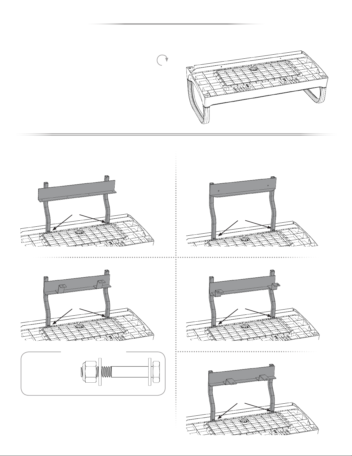
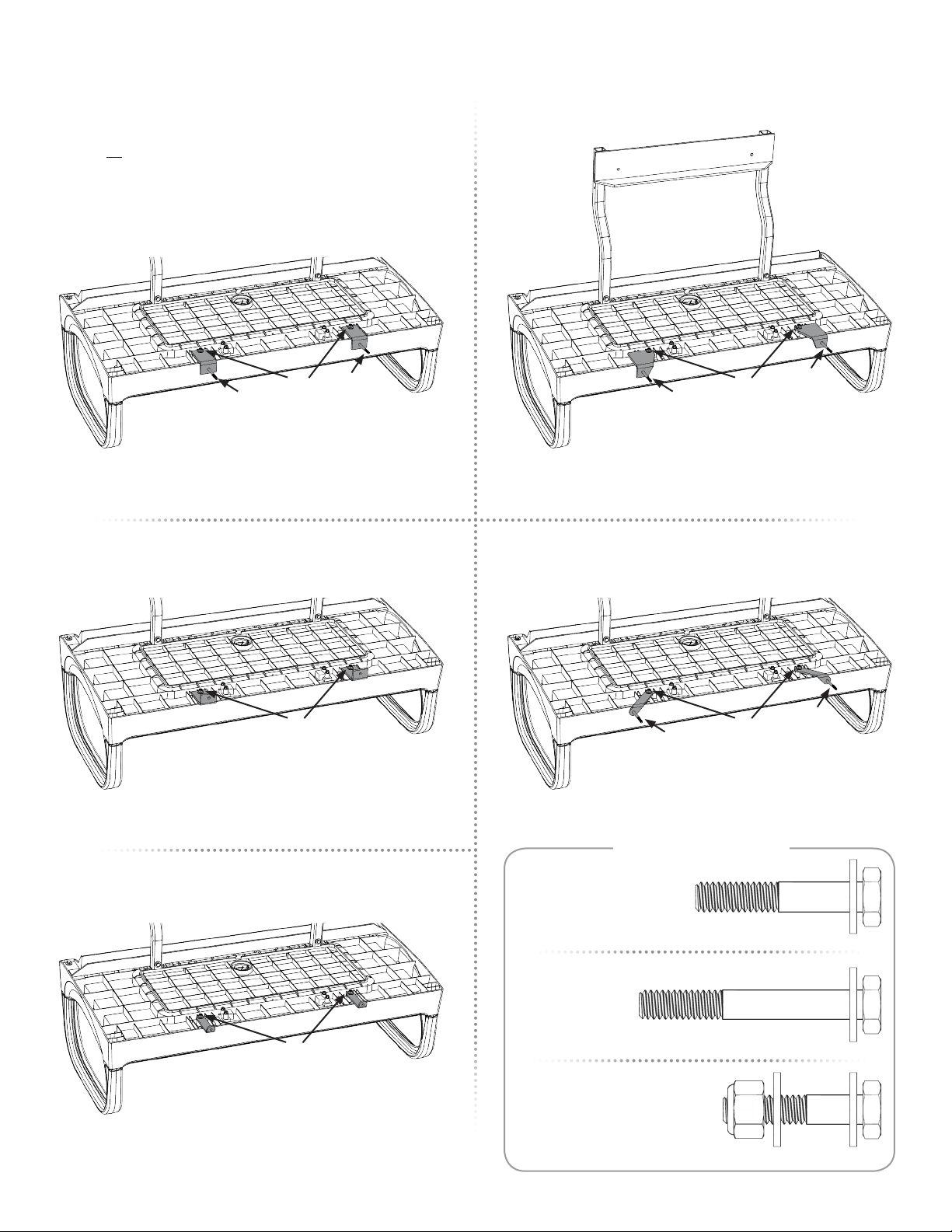
Section 2 - Seat Back Support Installation
Section 3 - Armrest Installation
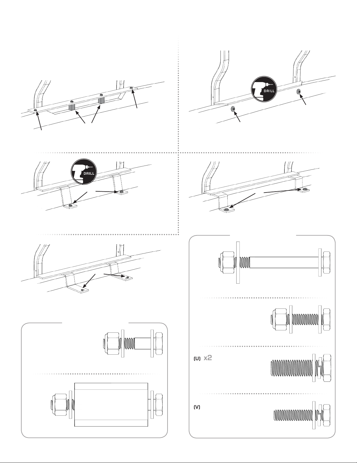
Section 4 - Footrest Supports and Bumper Angle Installation
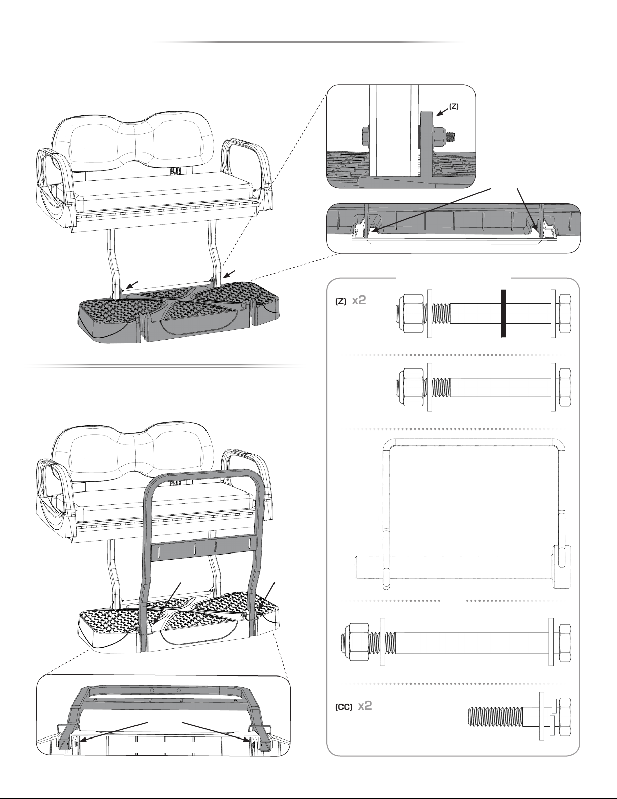
Section 5 - Rear Seat Mounting
Section 6 - Cushion Installation
Section 7 - Footrest, Safety Bar and Cup Holders Installation
Sold Separately
Chair Holder Easy Access Steps Drop-in Cargo Bed Golf Bag Holder Soft Cargo Carrier Storage Bin Trailer Hitch
OPTIONAL MAX 5 ACCESSORIES
PREPARE CAR FOR INSTALLATION
SECTION 1
Remove the following items to prepare the car for Rear Seat Kit Installation:
• Top
• Top Supports/Drain Tubes
• Bench Back Cushion
• Bag Rack Assembly
NOTE: Save and separate factory hardware for later use.
CAR PREPARATION
1:1
CAT-4: Max5 Rear Seat Kit / May 18, 2018 www.DoubleTakeGolfCar.com
MULTI–FUNCTION REAR SEAT
TM
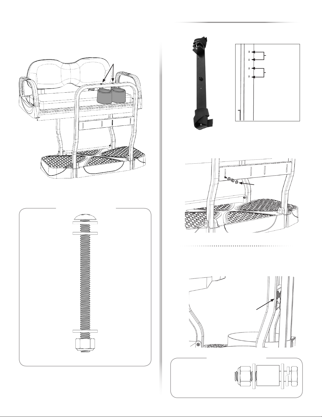
Supplied hardware has been illustrated at a 1:1 scale for the
ability to verify required lengths quickly and easily. Simply place
the hardware on top of the illustration to ensure you are using
the correct item and measurement.
SCALE HARDWARE GUIDE
• If you are installing a Storage Bin and decide to release the Storage Lid from the Seat Base before installing the
Seat Base and Seat Back Cushion onto the Car, do not try to open the Lid past 90°. Doing so may place too much
stress on the Lid Hinge possibly causing failure.
• Once the Seat Base and Seat Back Cushion are installed on the Car, the Seat Back Cushion acts as a stop for the
Lid protecting the Lid Hinge from hyper-extension.
• As a precaution, we recommend installing the Storage Lid Latch only after the Seat is fully installed on the Car.
DO NOT PUSH OR FORCE THE LID PAST 90° BEFORE SEAT BASE & SEAT BACK CUSHION ARE INSTALLED ON THE CAR

Manufactured By Custom Golf Car Supply, Inc.
SEAT BACK SUPPORT INSTALLATION
SECTION 2
POSITION AND INSTALL SEAT BACK SUPPORTS
2:1
NOTE: Fully tighten Bolts.
Front of Car Front of Car
(E)
Front of Car
Front of Car
(D)
E-Z-GO TXT / STAR
HW BAG: RSK SBS HW TXT
TXT - rear holes / Star - front holes
E-Z-GO RXV
FACTORY HW
YAMAHA DRIVE
FACTORY HW
CLUB CAR DS
HW BAG: RSK SBS HW DS
CLUB CAR PRECEDENT
HW BAG: RSK SBS HW PD
Front of Car
HARDWARE - SCALE 1:1
FACTORY HARDWARE
(E) x4
(C) x4
3/8” X 1-1/4” Hex Bolt - 3/8” Lock Washer - 3/8” Flat Washer
(D) x4
1/4” X 1-1/2” Hex Bolt - 1/4” Lock Washer - 1/4” Flat Washer
(A) x4
1/4” X 1-1/2” Hex Bolt - 1/4” Flat Washer (x2) - 1/4” Nyloc Nut
(C)
(B)
(C)
(C)
(B)
(C)
(A)
(A)
(E)
(B) x2
M8 X 40mm Hex Bolt - 1/4” Lock Washer - 1/4” Flat Washer
REUSE FACTORY HARDWARE FROM BAG RACK REMOVAL

CAT-4: Max 5 Rear Seat Kit - 3
ARMREST INSTALLATION
SECTION 3
(F) (F)
(G)
INSERT ARMRESTS IN BASE
3:2
SECURE ARMRESTS
3:3
NOTE: Fully tighten all hardware.
x2
x2
(H)
(I)
1/4” X 1-3/4” Threaded Stud
1/4” Flat Washer - 1/4” Nylock Nut
Square Nut
1/4” X 2-1/2” Hex Bolt - 1/4” Lock Washer - 1/4” Flat Washer
(G) x2
HARDWARE - SCALE 1:1
(F) x4
(I) x2
(H) x2
Insert short end of threaded stud (G) into square end of Armrest.
3:1
ARMREST PREPARATION
HW BAG: MAX5 ARMREST HW

Manufactured By Custom Golf Car Supply, Inc.
FOOTREST SUPPORTS AND BUMPER ANGLE INSTALLATION
SECTION 4
Place bottom side up for assembly.
NOTE: Place Seat on Cardboard or Blanket to prevent from scratching.
4:1
POSITION SEAT BASE
4:2
INSTALL BUMPER ANGLE
(J)
(J)
(J) (J)
(J)
NOTE: Fully tighten Hardware.
1/4” X 1-3/4” Hex Bolt - 1/4” Flat Washer (x2) - 1/4” Nyloc Nut
(J) x2
HARDWARE - SCALE 1:1
CLUB CAR DS
HW BAG: RSK BA HW DS
CLUB CAR PRECEDENT
HW BAG: RSK BA HW PD
E-Z-GO RXV
HW BAG: RSK BA HW RXV
E-Z-GO TXT / STAR
HW BAG: RSK BA HW TXT
YAMAHA DRIVE
HW BAG: RSK BA HW DRV

CAT-4: Max 5 Rear Seat Kit - 5
4:3
INSTALL REAR SEAT KIT BRACKETS
NOTE: Do not fully tighten Bolts until mounted to Seat Back Supports.
(M)
(M)
(M)
(M)
(K)
(L)
(K)
(K)
(L)
(K)
(M)
1/4” X 2” Hex Bolt - 1/4” Flat Washer
1/4” X 1-1/4” Hex Bolt - 1/4” Flat Washer (x2) - 1/4” Nyloc Nut
(L) x2
(M) x2
1/4” X 1-1/2” Hex Bolt - 1/4” Flat Washer
(K) x2
HARDWARE - SCALE 1:1
CLUB CAR DS
HW BAG: MAX5 BKT HW DS
**Insert bolts (K) before attaching brackets**
E-Z-GO TXT / STAR
HW BAG: MAX5 BKT HW TXT
E-Z-GO RXV
HW BAG: MAX5 BKT HW RXV
**Insert bolts (K) before attaching brackets**
YAMAHA DRIVE
HW BAG: MAX5 BKT HW DRV
HW BAG (DRIVE 2): MAX5 BKT HW D17
CLUB CAR PRECEDENT
HW BAG: MAX5 BKT HW PD
**Insert bolts (K) before attaching brackets**

Manufactured By Custom Golf Car Supply, Inc.
HARDWARE - SCALE 1:1
REAR SEAT MOUNTING
SECTION 5
5:1
ATTACH REAR SEAT KIT TO SEAT BACK SUPPORTS
Flip Rear Seat Base over and attach to Seat Back Supports.
NOTE: Do not fully tighten until Bumper Angle is attached in next step.
1/4” Flat Washer - 1/4” Nylock Nut
1/4” X 1-1/2” Hex Bolt - 1/4” Flat Washer (x2) - 1/4” Nylock Nut
1/4” X 1-3/4” Hex Bolt - 1/4” Flat Washer (x2) - 1/4” Nylock Nut
(N) x2
(O) x2
(P) x2
(N)
(N) (N)
(N)
(N)
(N)
(O)
(P)
(P)
(O)
E-Z-GO RXV
HW BAG: MAX5 BKT HW RXV
CLUB CAR DS
HW BAG: MAX5 BKT HW DS
CLUB CAR PRECEDENT
HW BAG: MAX5 BKT HW PD
E-Z-GO TXT / STAR
HW BAG: MAX5 BKT HW TXT
TXT - top holes / Star - bottom holes
YAMAHA DRIVE
HW BAG: MAX5 BKT HW DRV

CAT-4: Max 5 Rear Seat Kit - 7
HARDWARE - SCALE 1:1
1/4” X 1-1/4” Hex Bolt - 1/4” Flat Washer (x2) - 1/4” Nylock Nut
HARDWARE - SCALE 1:1
NOTE: Fully tighten Rear Seat Kit Brackets and Bumper Angle Hardware.
5:2
MOUNT BUMPER ANGLE TO CAR
(S)
(S)
(R)
(Q)
(Q)
(Q) x2
1/4” X 2-1/2” Hex Bolt - 1/4” Flat Washer (x2) - Spacer Square - 1/4” Nylock Nut
(R) x2
(S) x2
5/16” X 1-1/4” Hex Bolt - 5/16” Flat Washer (x2) - 5/16” Nylock Nut
(T) x2
(U) x2
(V) x2
M6 x 30mm Hex Bolt - 1/4” Lock Washer - 1/4” Flat Washer
3/8” X 1-1/4” Hex Bolt - 3/8” Flat Washer
1/4” X 2-1/2” Hex Bolt - 1/4” Flat Washer - 1/4” Fender Washer - 1/4” Nylock Nut
(T) (U)
(V)
CLUB CAR DS
HW BAG: RSK BA HW DS
CLUB CAR PRECEDENT
HW BAG: RSK BA HW PD
Chase drill holes through car bumper
E-Z-GO TXT / STAR
HW BAG: RSK BA HW TXT
Chase drill holes using existing holes in bagwell
E-Z-GO RXV
HW BAG: RSK BA HW RXV
Tabs will align with existing holes in bagwell
YAMAHA DRIVE
HW BAG: RSK BA HW DRV
Tabs will align with existing holes in bagwell

Manufactured By Custom Golf Car Supply, Inc.
6:1
SEAT BOTTOM CUSHION INSTALLATION
Angle Seat Bottom Plastic upright to 90° and insert 2/1 Seat Bottom
Cushion in the top center hole using the Temporary Stud.
Insert Temporary Stud (S) into the 2/1 Seat Bottom Cushion then slip the
2/1 Strap (T) over the Temporary Stud as shown below.
Remove the Temporary Stud.
NOTE: Fully tighten Hardware.
6:2
SEAT BACK CUSHION INSTALLATION
Installation instructions are provided in the Seat Plate Kit Hardware Box,
located in the 2/1 Cushion Box.
CUSHION INSTALLATION
SECTION 6
(W)
Loosely screw in all four corner holes first, then screw in the remaining
vacant holes.
NOTE: Do not fully tighten.
(Y)
(Y)
(Y)
(Y)
(X) Tag
HARDWARE - SCALE 1:1
1/4” X 1-1/4” FHP Screw
Temporary Stud
(W) x1
(Y) x10
2/1 Strap (Not to Scale)
(X) x1
BOTTOM CUSHION
HW BAG: MX5GRDN CSHN HW
HW BAG: MX5GRDN CSHN HW HW BAG: MX5GRDN CSHN HW

CAT-4: Max 5 Rear Seat Kit - 9
(AA)
OPTIONAL
Shown from below
7:2
SAFETY BAR INSTALLATION
7:1
FOOTREST INSTALLATION
NOTE: Fully tighten Hardware.
FOOTREST, SAFETY BAR AND CUP HOLDERS INSTALLATION
SECTION 7
(BB) (BB)
Shown from below
Shown from back
(Z)
(Z)
FOOTREST BOTTOM
(Z)
1/4” X 2-1/4” Hex Bolt - 1/4” Flat Washer (x2) - 1/4” Nyloc Nut
1/4” X 2-1/4” Hex Bolt - 1/4” Plastic Washer - 1/4” Flat Washer (x2) - 1/4” Nyloc Nut
5/16” X 3” Hex Bolt - 5/16” Flat Washer (x2) - 5/16” Nyloc Nut
1/4” X 1-1/4” Hex Bolt - 1/4” Lock Washer - 1/4” Flat Washer
(Z) x2
(AA) x2
(BB1) x2
(CC) x2
HARDWARE - SCALE 1:1
5/16” D-Ring Pin
(BB2) x2
OR
INSTALL FOR FOLDING SAFETY BAR
ONLY INSTALL TO LOCK
FOLDING FOOTREST FUNCTION
ONLY INSTALL TO LOCK
FOLDING SAFETY BAR FUNCTION
INSTALL TO LOCK FOLDING SAFETY BAR
HW BAG: MAX5 FOOTREST HW
HW BAG: MAX5 SAFETY BAR HW
(CC)
OPTIONAL
FOOTREST BOTTOM

Manufactured By Custom Golf Car Supply, Inc.
7:3
CUP HOLDER INSTALLATION
NOTE: Fully tighten Hardware.
(DD)
(DD) x2
HARDWARE - SCALE 1:1
1/4” X 3-1/2” Truss Screw
-
1/4” Flat Washer (x3)
-
1/4” Nylock Nut
Club Car
Precedent Only
All Other
Cars
OPTIONAL ACCESSORY (Sold Separately)
GOLF BAG HOLDER
(EE)
Thread (EE) thru Safety Bar cross brace slot, then into the lowest hole set for
your Car Model.
Follow up with (EE) in the top hole set for your Car Model.
NOTE: Fully tighten Hardware.
STORAGE BIN
HARDWARE - SCALE 1:1
1/4” X 1-1/2” Hex Bolt - 1/4” Lock Washer - 1/4” Flat Washer (x2) - 1/4” Spacer - 1/4” Nyloc Nut
(EE) x2
BOTTOM INSIDE
OF BAG HOLDER
(EE)

CAT-4: Max 5 Rear Seat Kit - 11
OPTIONAL ACCESSORY (Sold Separately)
STORAGE BIN
INSTALL LATCH HANDLE
Remove the two Lid Screws (FF) from under the Seat Base.
Squeeze the two small clips (GG) together to remove the Hole Cap.
NOTE: Fully tighten Hardware.
Pull the Handle up to draw in the catch (HH).
Align the Bottom Latch
Cover and install with provided hardware
(II)
.
NOTE: Fully tighten Hardware.
(FF)
(GG)
(HH)
(II)
(II)
INSTALL BIN
Insert the Bin into the opening, making sure the Notch is facing the Seat Hinge.
OPTIONAL: Using a 13/32” drill bit, add a Drain Hole in the bottom of the
Storage Bin before installation.
NOTE: The provided drain plug is designed to fit a 13/32” hole.
Make sure the Bin rests inside the Bin Ridge in the Seat Base. Install the
self-tapping Screws thru all holes in Bin into the Seat Base.
Drain Hole
Screw Hole
Screw
Bin Ridge
12
SEAT HINGE
SEAT BASE
BIN
TOP VIEW – SEAT HINGE
• If you are installing a Storage Bin and decide to release the Storage Lid from the Seat Base before installing the
Seat Base and Seat Back Cushion onto the Car, do not try to open the Lid past 90°. Doing so may place too much
stress on the Lid Hinge possibly causing failure.
• Once the Seat Base and Seat Back Cushion are installed on the Car, the Seat Back Cushion acts as a stop for the
Lid protecting the Lid Hinge from hyper-extension.
• As a precaution, we recommend installing the Storage Lid Latch only after the Seat is fully installed on the Car.
DO NOT PUSH OR FORCE THE LID PAST 90° BEFORE SEAT BASE & SEAT BACK CUSHION ARE INSTALLED ON THE CAR
NOTCH OPTIONAL DRAIN HOLE
(13/32” Drill Bit)

Manufactured By Custom Golf Car Supply, Inc.
OPTIONAL ACCESSORY (Sold Separately)
TRAILER HITCH
INSTALL HITCH RECEIVER
Remove Nuts and Washers from the Bolts in the center of the Footrest.
Place Hitch Receiver (JJ) over Bolts and reinstall the Washers and Nuts.
NOTE: Fully tighten Hardware.
(JJ)
1
ATTACH HITCH TO RECEIVER
Attach Hitch (KK) to the Hitch Receiver with provided D-Ring Pins (LL).
Install the Hitch Ball size of your choice (not included).
(KK)
(LL)
Hitch Ball Hole
2
Table of contents
Other DoubleTake Automobile Accessories manuals
Popular Automobile Accessories manuals by other brands

Metra Electronics
Metra Electronics 99-5838CH installation instructions

Monster
Monster iCruze MPC FX IC-AUD1 Installation & user guide

SimworX
SimworX PRO Series Setup manual

Arnott
Arnott SK-2806 installation manual

HAUL MASTER
HAUL MASTER 95408 Assembly and operating instructions

KFI
KFI OPEN TRAIL instruction manual

Prorack
Prorack WHISPBAR S53 Fitting Instructions for Basic Carrier

Atera
Atera SIGNO 044 301 installation instructions

Reyco Granning
Reyco Granning IFS 1660S3 owner's manual

Car-Interface
Car-Interface v.LiNK CI-VL2-PC-HSD manual

Discount Car Stereo
Discount Car Stereo A2D-C5FM installation guide

RITE-HITE
RITE-HITE DOK-LOK VBR-600 installation manual