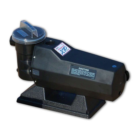
Doughboy 0-1063-020 User manual

Pool Power Pak®I
Timer Models: 0-1063-020, 0-1064-020,
0-1065-020, 0-1066-020 with 25 Ft. Cord
Timer Models: 0-1063-026, 0-1064-026,
0-1065-026, 0-1066-026 with 3 Ft. Cord
Owner's Guide
365-1878

2
PREPARATION
IMPORTANT SAFETY INSTRUCTIONS
FOR ALL MODELS:
When installing and using this electrical equipment,
basic safety precautions should always be fol-
lowed, including the following:
1. READ AND FOLLOW ALL INSTRUCTIONS.
2. WARNING: To reduce the risk of injury, do not
permit children to use this product unless they are
closely supervised at all times.
3. WARNING: Risk of electric shock. Connect only to
a grounding type receptacle protected by a Ground
Fault Interrupter (GFCI).
Contact a qualified electrician if you cannot verify that
the receptacle is protected by a GFCI.
4. Do not bury cord. Locate cord to minimize abuse
from lawn mowers, hedge trimmers, and other equip-
ment.
5. WARNING: To reduce the risk of electric shock,
replace damaged cord immediately.
6. WARNING: To reduce the risk of electric shock, do
not use an extension cord to connect unit to the
electrical supply; provide a properly located outlet.
FOR MODELS 0-1063-020, 0-1064-020, 0-1065-020,
0-1066-020 (25 Ft. Cord)
7. CAUTION: This pump is for use with storable pools
only. Do not use with permanently installed pools. A
storable pool is constructed so it may be readily disas-
sembled for storage and reassembled to its original
integrity. A permanently installed pool is constructed in
or on the ground or in a building such that it cannot be
readily disassembled for storage.
FOR MODELS: 0-1063-026, 0-1064-026, 0-1065-026,
0-1066-026 (3 Ft. Cord)
8. CAUTION: This pump is for use with permanently
installed pools and may also be used with hot tubs and
spas if so marked. Do not use with storable pools. A
permanently installed pool is constructed in or on the
ground or in a building such that it cannot be readily
disassembled for storage. A storable pool is con-
structed so that it may be readily disassembled for
storage and reassembled to its original integrity.
FOR ALL MODELS:
9. SAVE THESE INSTRUCTIONS.
ELECTRICAL SOURCE
FOR MODELS 0-1063-020, 0-1064-020, 0-1065-020,
0-1066-020 (25 Ft. Cord)
Your pump is supplied with a 25 foot, 3-wire electrical
cord and a 3-pronged plug. The pump is double insu-
lated and grounded. The pump electrical cord must be
connected to a grounded, 3-wire, 115 VAC electrical
receptacle.
The pump should be connected to a receptacle on a
dedicated circuit protected by a 20 AMP circuit breaker.
DO NOT use a grounding adaptor.
The receptacle must be protected by a Ground Fault
Circuit Interrupter (GFCI) in accordance with Article 680-
31 of the National Electrical Code (NEC), (Section 68-
204 of the Canadian Electrical Code (CSA) and local
codes or ordinances. For runs greater than 25 feet,
consult your local licensed electrical contractor.
FOR MODELS: 0-1063-026, 0-1064-026, 0-1065-026,
0-1066-026 (3 Ft. Cord)
Your pump is supplied with a 3-foot, 3-wire electrical
cord and a 3-prong flanged, twist-lock plug.
The pump electrical cord must be connected to a single
twist lock, grounding type receptacle that is located a
minimum of 5 feet from the inside pool wall.
A qualified electrical contractor must install this recep-
tacle in accordance with Article 680-6 of the National
Electrical Code (NEC). A Ground Fault Interrupter
(GFCI) must be used. An ON/OFF Switch must be
installed at the receptacle.
Use a Hubbell No. 2310 Receptacle, 20 AMP 125 Volt
A.C. or an equivalent receptacle that meets NEMA
Configuration L5-20R.
This pump is double insulated and grounded. Dead
metal parts are not in contact with pool water.
CAUTION
1. DO NOT install the pump on a deck, it could fall into
the water, causing severe electrical shock. Do not
install on any surface at, above, or slightly below the
top rail of the pool.
2. DO NOT allow children or adults to climb, sit, or
stand on the pump unit. They could easily fall.
Position the filter and pump approximately 4 feet
from the pool wall so they may not be used as steps
by children.
3. Always keep the water level in your pool between the
water level markers on the skimmer face plate. If the
pump is run with water level too low, the pump seal
may overheat and cause permanent damage to the
pump.
4. Your Pool Power Pak must sit either in an optional
filter/pump base, on a patio block, or on any firm
surface that slightly elevates the pump off the
ground. This keeps water away from the motor and
prevents the vents of the Power Pak from becoming
blocked, which could cause the motor to overheat.
STRAINER ASSEMBLY INSTALLATION
Sequel I Plus or Silica I Plus - The Strainer Assembly
is packed with the filter. Refer to your Sequel I Plus or
Silica I Plus Owner’s Guide to learn how to install the
1. Select 6 hours running time with the timer knob.
2. Plug pump in and pump will start.
3. Pump will shut off at the end of six hours (2:00
p.m.).
4. Pump will turn on automatically the following day
(Sunday), 24 hours from the time it was plugged in
(8:00 a.m.).
5. In our example, the pump will start every day at
8:00 a.m., and shut off every day at 2:00 p.m.
MANUAL SETTINGS:
To operate the pump with the manual settings, set the
switch in either the “OFF” or the “CONT” position.
Selecting the “CONT” position allows you to run the
pump continuously for functions such as vacuuming or
extended filtering.
Selecting the “OFF” position cuts power to the motor.
Selecting “OFF” will also reset the “start-time" and
cycle you selected by plugging in the pump.
Example: Using same day and time, the pump has run
from 8:00 a.m. until 10:00 a.m. and has four hours
remaining in the 6 hour cycle:
1. Switch pump “OFF” at 10:00 a.m. and leave it off
until 11:00 a.m. (one hour).
2. Switch pump back to 6 hour setting at 11:00 a.m.
Pump will start and run for 6 hours, then shut off
automatically at 7:00 p.m.
TO CHANGE THE LENGTH OF TIME THE PUMP
WILL RUN:
Turn the timer knob to the new hour selection desired
(you do not need to switch pump off).
Examples:
1. The switch is on a run-time hour setting (4, 6, 8,
10 or 12), but the pump is not running: Any
newly selected time length will take effect the
following day at the regular "start-time".
2. The switch is on a run-time hour setting (4, 6, 8,
10 or 12), and the pump is running: If the new
selected time length is shorter than the current
time length, the pump will shut off according to the
new selection.
3. The switch is on a run-time hour setting (4, 6, 8,
10 or 12), and the pump is running: If the new
selected length of time is longer than the current
length of time indicated, the pump will continue
running and shut off after the new selected length
of time.
TO CHANGE THE TIME THE PUMP WILL START:
There are two methods to reset the start time in auto
mode (switch set to a run-time hour).
3
Strainer Assembly on the Pool Power Pak I - The
male hose adaptor (1) provided with your Power Pak is
not required when a Strainer Assembly is installed on
the pump.
Skim Line Filter - Strainer Assembly is optional. If not
used, then screw the male hose adaptor (1) into the
threaded suction port of the pump volute (3) and tighten
firmly. This adaptor must be installed if no Strainer
Assembly is used.
INITIAL START-UP
1. If you have a Doughboy filtration system, follow the
"Initial Start-Up" instructions in the Doughboy Filter
owner's guide.
2. If this pump has been purchased as a replacement
(and you are not referring to the Doughboy Filter
instructions), the pump will have to be primed after
all hose connections have been made and pool has
been filled to the proper level. To prime the pump,
loosen the pump strainer pot lid to allow air to
escape. Tighten lid when water begins to flow
between strainer pot body and lid. Do not
overtighten.
TIMER OPERATION
To access the timer, lift the timer cover at rear of pump.
AUTO SETTING:
This pump is equipped with an automatic timer which
has three modes of operation: “OFF,” “AUTO” and
“CONT.” In automatic mode, there are five lengths of
run-times to choose from: 4, 6, 8, 10, or 12 hours.
To operate the pump in the automatic mode, select the
run-time (in hours). The timer operates on a 24 hour
cycle which starts when the pump is plugged in ("start-
time").
After plugging in the pump, the pump will run for the
number of hours selected, then shut off automatically.
The pump will automatically start again 24 hours from
the time it was plugged in ("start-time").
Example (the current day and time is Saturday, 8:00
a.m.):
CONTINUOUS
(Manual On)
AUTO MODE
RUN-TIME
HOUR
SETTINGS
TIMER FACE

4
1. To change the time that the pump will start, unplug
the pump. Plug the pump back in at the desired
start time. You must wait a minimum of 30
seconds between unplugging and replugging.
2. Turn the switch to the "OFF" position and then
back to a run-time hour setting. The new run-time
will begin immediately and complete the run-time
cycle.
NOTE: In the event of a power failure, the timer will
act as though it has been unplugged, then replugged
when power is restored. In the auto mode, the pump
will start running its cycle when power is restored.
You will have to reset your “start-time" by unplugging
the pump, then replugging it at your desired “start-
time", or follow method two above.
MAINTENANCE
Make sure the pump is disconnected from the
electrical source before attempting any mainte-
nance work.
LUBRICATION
Periodically lubricate the O-Ring under the strainer
cover with a NON-PETROLEUM lubricant recom-
mended for A.B.S., Noryl and Acrylic plastics. Consult
your pool dealer for lubricant selections.
If you have any questions or require assistance,
contact your Doughboy pool dealer.
SERVICING SAFETY TIPS
1. ALWAYS TURN “OFF” the main power switch and the
Ground Fault Circuit Interrupter (GFCI) breaker switch so
power is completely off before servicing your unit.
2. ALWAYS BE SURE THE GROUND UNDER YOUR FEET
AND YOUR BODY IS DRY before you touch electrical
equipment. Failure to heed this warning may cause
personal injury due to severe electrical shock.
3. ALWAYS have a qualified electrician service your system
if electrical problems occur. This system uses UL listed
components and must be serviced by a qualified electri-
cian to insure that the electrical integrity is maintained.
Failure to do so may cause personal injury due to severe
electrical shock.
4. ALWAYS have a qualified electrician install a Ground
Fault Circuit Interrupter (GFCI) breaker at the electrical
service or supply panel. Follow GFCI manufacturer’s
operating instructions for testing. Failure to do so may
cause personal injury due to severe electrical shock.
CAUTION: To reduce the risk of electrical shock, connect
only to grounding type receptacles. A Ground Fault
Circuit Interrupter (GFCI) must be provided in accor-
dance with local codes or ordinances.
CAUTION: To reduce the risk of electrical shock, use
only Original Equipment Manufactured (OEM) replace-
ment parts when servicing.
1
2
3
4
5
6
7
8
9
10
11
12
13
14
15
1
6
1
1
1
1
1
1
1
1
1
1
1
1
1
2
1
1
1
1
1
1
Male Hose Adaptor
#8 x 1" Phillips Screw
Pump Volute
O-Ring Seal
Impeller Assy. w/seal,
1/3 HP
Impeller Assy. w/seal
1/2 HP
Impeller Assy. w/seal
3/4 HP & 1 HP
5/8" Pump Seal Set
Pump Seal Seat
5/8" Pump Seal
Pump Faceplate Assy.
Motor, 1/3 HP
Motor, 1/2 HP
Motor, 3/4 HP
Motor, 1 HP
Motor Clamp
1/4"-20 Hex Nut
1/4"-20 x 1" Bolt
Insulating Sleeve
1/3 HP Pump Assy.
1/2 HP Pump Assy.
3/4 & 1 HP Pump Assy.
16
17
18
19
20
21
22
23
24
25
26
27
28
29
30
31
32
33
34
35
348-1026
1150-1000
1150-1005
330-1023
1100-1118
1100-1115
303-1104
303-1120
1121-1776
1100-1117
1100-1116
1121-1777
340-1645
308-1106
308-1107
340-2341
340-2344
1100-1690
330-1285
343-1074
327-1036
365-1878
—
2
1
1
10
1
1
1
1
1
1
1
1
1
1
1
1
1
1
1
1
1
1
1
Rubber Strip
Bottom Housing Assy.(-020 Models)
Bottom Housing Assy.(-026 Models)
#8 x 5/8" Screw
Cord Set Assy, 25'(-020 Models)
Cord Set Assy, 3' (-026 Models)
Strain Relief Bushing (-020 Models)
Strain Relief Bushing (-026 Models)
Top Housing/Decal Assembly.
Jumper Wire - Black
Jumper Wire - White
Timer Cover/Decal Assembly
Timer Body
Face Gasket
Body Gasket
Timer Mounting Bracket
Timer Knob
Timer Module Assembly
#8 x 1-1/2 Screw
Switch Hole Cover Plug
#8 Ext. Tooth Lockwasher (not shown)
Owner’s Guide
Warranty Card
ITEM P/N QTY DESCRIPTION ITEM P/N QTY DESCRIPTION
340-1778
330-1016
305-1010
308-1005
1107-1143
1107-1142
1107-1141
1121-1577
308-1263
308-1264
1121-1582
300-1015
300-1016
300-1017
300-1043
385-1152
321-1004
324-1018
341-1123
1121-1583
1121-1584
1121-1585
PARTS LIST

5
POOL POWER PAK I®TIMER MODELS - EXPLODED VIEW
Models With 25 Ft. Cord:
0-1063-020, 0-1064-020, 0-1065-020, 0-1066-020
Models With 3 Ft. Cord:
0-1063-026, 0-1064-026, 0-1065-026, 0-1066-026

DOUGHBOY RECREATIONAL • 10959 Jersey Blvd., • Rancho Cucamonga, CA 91730
Visit our web site at www.doughboy-pools.com
DB11001-018 Made in the United States of America Copyright © 2001
Change of Design: Doughboy Recreational expressly reserves the right to change or modify the
design and construction of any product in due course of our manufacturing procedures, without
incurring any obligation or liability to furnish or install such changes or modifications on products
previously or subsequently sold.
This manual suits for next models
8
Table of contents
Other Doughboy Swimming Pool Pump manuals
Popular Swimming Pool Pump manuals by other brands

Pentair
Pentair Teel 4RJ93 Operating instructions & parts manual

BADU
BADU JET Smart Operating and installation instruction

Intex
Intex Krystal Clear SF15110 Owners manul

Hayward
Hayward HP55BEE Installation and user manual

UK POOL STORE
UK POOL STORE UKPS16 instructions

Pentair
Pentair SWIMMEY Series installation guide