www.doulton.com
7. Position the Filter and Assemble the Filter for each
Housing – see figure 5a to 5d
7.1 Mark the required head position for fixing using the paper template supplied
Figure 5a
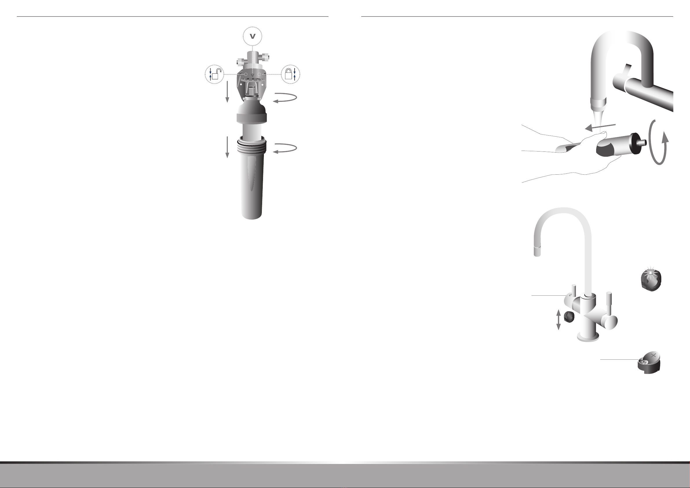
7.2 Grip the grey filter caps (E) and twist to the ‘unlock’ position
7.3 Pull down to disengage the filter caps (E) from the heads (C) and put the
filter caps (E) and filter bodies (F) to one side
7.4 Remove all packaging and fix the mounting plate (B) and filter heads (C) to
the unit or wall with the 6 screws (D) provided
Figure 5b
7.5 Unscrew the filter bodies (F) from the filter caps (E), open the filters and
discard the protective bags from the pre filter (G) of the left hand housing
and the ceramic filter (H) of the right hand housing
Figure 5c
7.6 Screw the threaded pre filter (G) into the grey filter cap (E) of the left hand
housing until washer resistance is felt, repeat for the ceramic filter (H) for
the right hand housing - do not over tighten
7.7 Screw the white filter bodies (F) into the grey filter caps (E) until a positive
stop is felt
Figure 5d
7.8 Align the arrow on the grey filter cap (E) of the assembled pre filter to the
unlock position on the left hand filter head (C) and push the assembled
filter firmly into the head until the clicks into position. Repeat this for the
assembled ceramic filter into the right hand filter head.
7.9 Twist the grey filter cap (E) of the assembled pre filter until the arrow is
aligned with the locked position on the left hand filter head (C). Check that
the arrows align to ensure that the filter is fully locked. Repeat this for the
assembled ceramic filter into the right hand filter head
Note: it is important that pre filter and ceramic filter are fitted in
the correct locations - See figure 6
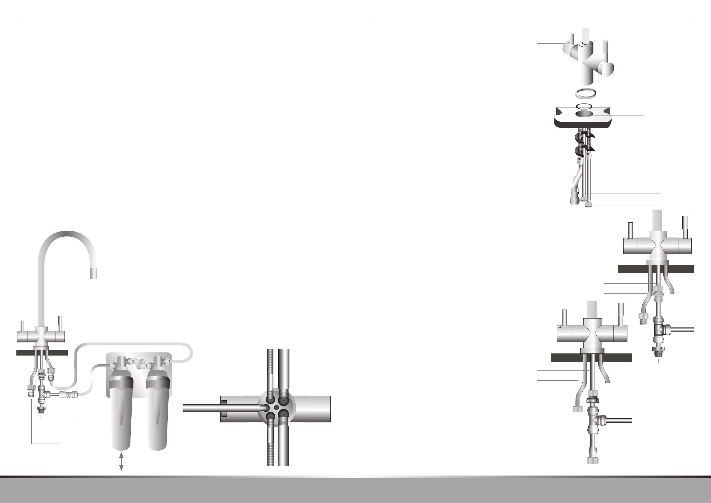
8. Install the pipe work and non return valve – see
figure 6
8.1 Measure and cut the tubing (I) to the length required to connect the inlet
port of left hand filter head (C) to the Tee adaptor (K). The length of the
tubing must be a minimum of 200 mm (8”). Take the cut length of tubing
and cut it in half
8.2 Fit one end of each tube into the non return valve (J)
8.3 Connect the non return valve (J) to the inlet port of the left hand filter head
(C) and the tee adaptor (K) with the tubing (I). Ensure that the flow arrow
on the non return valve (J) is pointing in the direction of the filter head (C)
8.4 Measure and cut the tubing (I) to the length required to connect the
outlet port of the right hand filter head (C) to the 7/16” adaptor (N) on the
filtered water hose on the mixer tap. Connect the tubing to the filter head
outlet port and mixer tap
8.5 Check that the arrows on non return valve (J) and the ports of the left
and right hand filter heads (C) are pointing in the correct direction of flow
towards the mixer tap – see page 1 and figure 7
9. Check the system for leaks
For guidance on identification of system components see page 1 and
figure 1
9.1 With the mixer tap filtered and hot/cold water taps open, slowly turn on the
mains water to allow the system to fill gradually until all of the trapped air
has been expelled from the system
9.2 Check for leaks around the mains supply pipes and adaptors, non return
valve, filter head inlet and outlet ports and filtered water adaptor. Also
check for leaks between the filter head, cap and filter body
9.3 If there are leaks from the adaptors, non return valve or filter head
ports:
• Turnoffthemainswatersupply
• Openthemixertaplteredandhot/coldwatertapstoreleasepressure
from the system
• Pressinonthecollararoundthetubingwhereitenterstheadaptor,see
figure 8
• Pullthetubingtoreleaseitfromtheadaptor
• Checktomakesurethatthetubingiscutsquareandthatthatitisnot
scratched or crimped
• Ifthetubingisunevenlycutorscratched,cutoffthedamagedsection
squarely and re install the tubing
• Withthemixertaplteredandhot/coldwatertapsopen,slowlyturnonthe
mains water to allow the system to fill gradually
• Checkthesystemforleaks
9.4 If there are leaks from the filter head:
• Turnoffthemainswatersupply
• Openthemixertaplteredandhot/coldwatertapstoreleasepressure
from the system
• Removethelterassembly,asdescribedinsection7.2–7.3/gure5a
• ChecktheO-ringsaroundthetopofthegreyltercap(E), ensure that
they are in place and free from dirt and particles, see figure 9
• Re-tthelterassembly,asdescribedinsection7.8–7.9/gure5d
• Withthemixertaplteredandhot/coldwatertapsopen,slowlyturnonthe
mains water to allow the system to fill gradually
• Checkthesystemforleaks
9.5 If there are leaks from the filter cap and filter body:
• Turnoffthemainswatersupply
• Openthemixertaplteredandhot/coldwatertapstoreleasepressure
from the system
• Removethelterassembly,asdescribedinsection7.2–7.3/gure5a
• Unscrewthelterbody (F) from the filter cap (E)
• ChecktheO-ringaroundthetopofthelterbody,ensureitisinplaceand
free from dirt and particles
• Removethelterelementbyunscrewingfromtheltercapandplaceto
one side ensuring that the open ended plastic mount is kept clean to avoid
contamination
• ChecktheinsideoftheltercaponthesurfacewherethebodyO-ring
seals, ensure it is free from dirt and particles, see figure 9
• Retthethreadedlterelementandreassemblethelterasdescribedin
section 7.6 – 7.9/ figures 5c & 5d
• Withthemixertaplteredandhot/coldwatertapsopen,slowlyturnonthe
mains water to allow the system to fill gradually
• Checkthesystemforleaks
9.6 If there are leaks from the mixer tap adaptor:
• Turnoffthemainswatersupply
• Openthemixertaplteredandhot/coldwatertapstoreleasepressure
from the system
• Pressinonthecollararoundthetubingwhereitentersthe7/16”tap
adaptor (N).See figure 8
• Pullthetubingtoreleaseitfromtheadaptorandunscrewtheadaptorfrom
the filtered water flexible supply pipe on the mixer tap
• Checkthattheblacksealingwasheriscorrectlyseatedinthethreaded
hole of the tap adaptor
• Makesuretheblacksealingwasherisundamagedandfreefromdirtand
particles
• Screwthetapadaptor (N) to the filtered water flexible supply pipe on the
mixer tap - do not over tighten
• Ensuresurethatthetubingiscutsquareanditisnotscratchedorcrimped
• Ifthetubingisunevenlycutorscratched,cutoffthedamagedsection
squarely and re install the tubing
• Withthemixertaplteredandhot/coldwatertapsopen,slowlyturnonthe
mains water to allow the system to fill gradually
• Checkthesystemforleaks
10. Prepare the filter for use
10.1 The 3 way mixer tap (Q) has an indicator light to inform the user when the
ceramic filter requires changing. The light flashes ‘blue’ when the filtered
water tap is operated, if the light flashes ‘red’ the ceramic filter requires
changing. Remove the plastic battery protection strip from the underside
of the mixer tap filtered water tap lever to enable the filter replacement
indicator function, see figure 2b
10.2 Open the mixer tap filtered water tap and run the water to waste for
10 minutes (or 15 litres)
10.3 Leave to stand for 24 hours to condition the ceramic filter element, then
run water to waste for a further 10 minutes. The filter is now ready for use
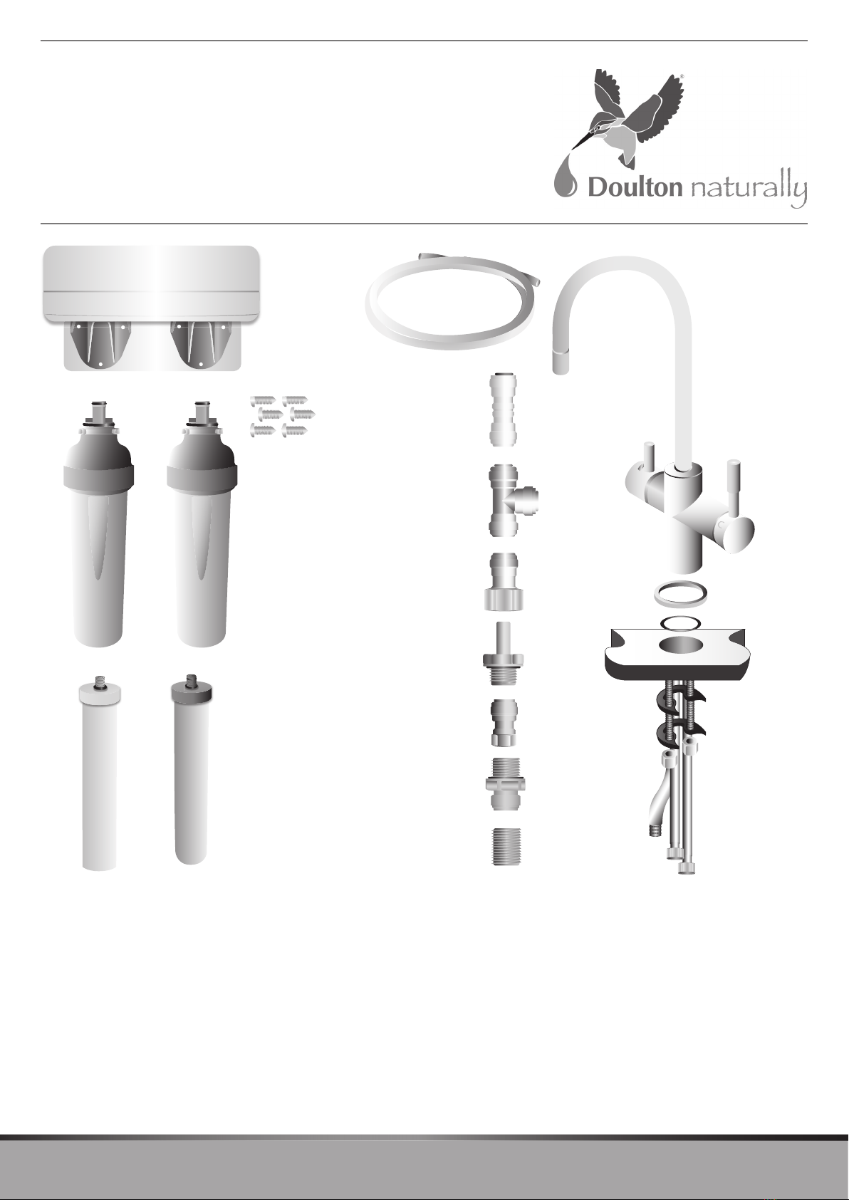
Figure 5a Figure 5b
Figure 5c Figure 5d
C
E
E
G/H
F
C
E
F
Figure 7
Direction of flow
Incoming mains
water
To mixer tap
Bag
F
Push collar
Pull
Tubing Collar Adaptor Body O-ring seal face inside
Figure 8 Figure 9 O-ring
O-ring
Figure 6
N
K
I
M
Mains cold
water supply
Q. 3 way Mixer Tap
J
P
O
I
I
I
E
F
Prefilter Ceramic Filter
G/H