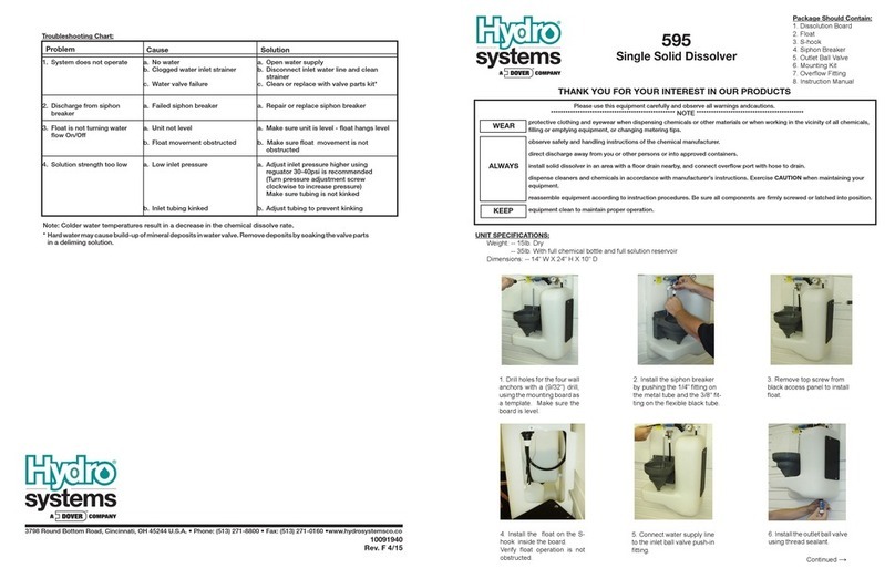
Dover Hydro systems 595MD User manual
Other Dover Dispenser manuals

Dover
Dover HYDRO DM-500 User manual
Dover
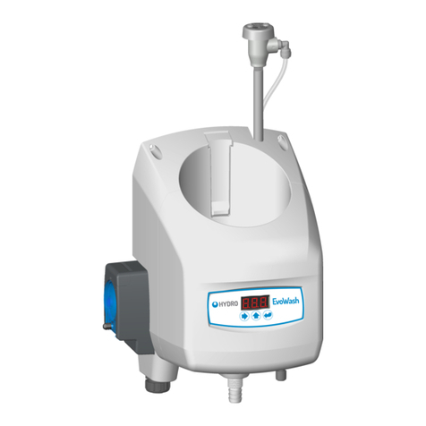
Dover HYDRO EvoWash User manual
Dover
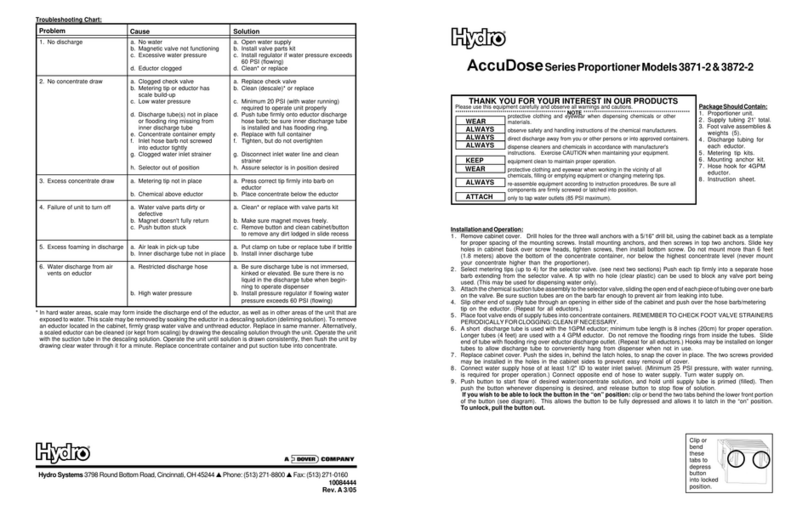
Dover Hydro AccuDose Series User manual
Dover
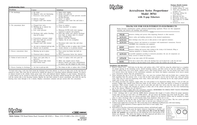
Dover Hydro AccuDose Series User manual
Dover
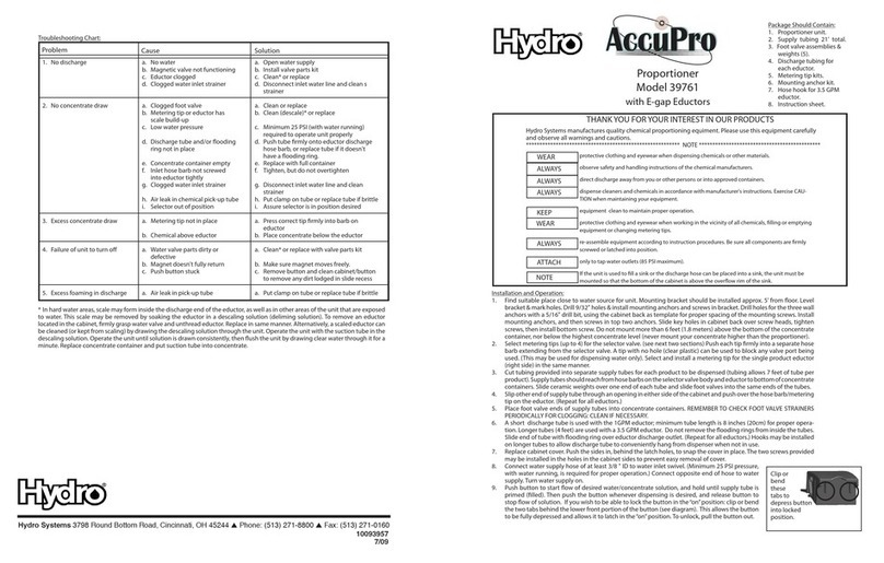
Dover Hydro AccuPro User manual

Dover
Dover Hydro AccuPro User manual

Dover
Dover Hydro AccuDose Series User manual

Dover
Dover Hydro AccuDose Series User manual

Dover
Dover Hydro AccuPro User manual

Dover
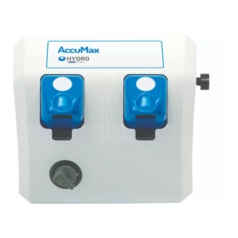
Dover Wayne Helix WM048523 User manual
Dover
Dover Hydro AccuDose Series User manual

Dover
Dover Hydro AccuDose Series User manual

Dover
Dover Hydro AccuDose Series User manual

Dover
Dover Wayne Select S1 Guide

Dover
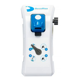
Dover Hydro AccuPro User manual
Dover
Dover Hydro Accumax QDV User manual
Dover
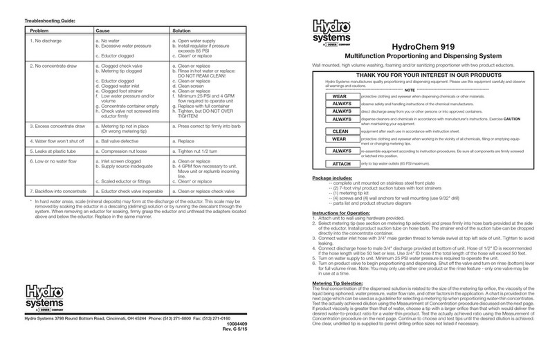
Dover Hydro systems HydroChem 919 User manual
Dover
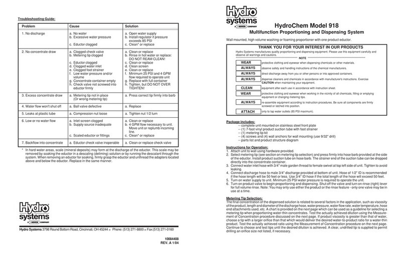
Dover Hydro systems HydroChem 918 User manual
Dover
Dover Hydro systems 595 User manual

Dover
Dover Hydro AccuPro User manual
Popular Dispenser manuals by other brands

Silver King
Silver King Majestic SK12MAJ Technical manual and replacement parts list

Franke
Franke F3Dn Twin Service manual

STIEBEL ELTRON
STIEBEL ELTRON UltraHot Plus Operation and installation instructions

DAN DRYER
DAN DRYER 282 installation guide

Essity
Essity Tork 473208 manual

CBS
CBS SD300BU-88 COMPONENT MAINTENANCE MANUAL WITH ILLUSTRATED PARTS LIST


