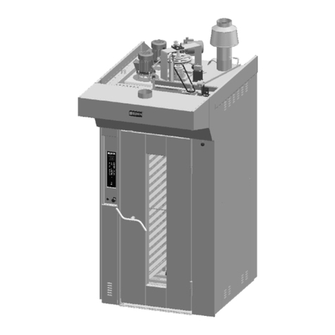
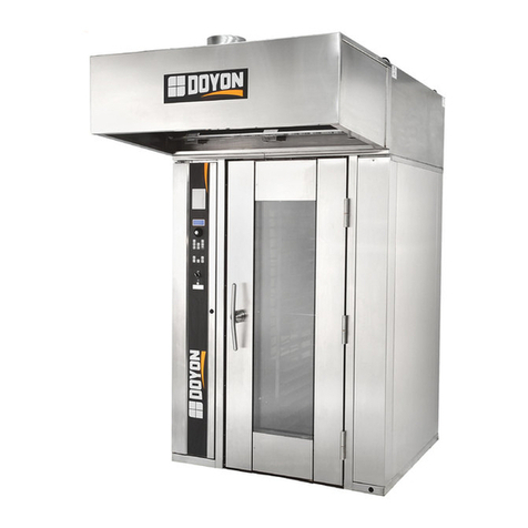
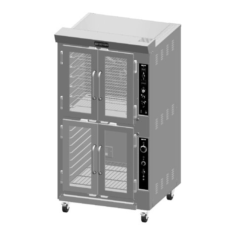
Doyon Artisan User manual

Doyon Artisan
Instruction Manual

MODULRAM DIGITAL | Edition A - Revision 0
Instruction Manual | 2
Table of contents
01. Oven technical information················································································· 3
02. Connections to be made to the oven (control panel ELE.D14) ·············································· 5
2.1 Steam, water, drain and electrical connections ························································ 5
2.2 Cable accessories that come with oven ······························································· 5
03. First time heating process (control panel ELE.D14) ·························································· 6
04. Description of control panel display ELE.D14 ······························································· 7
4.1 Operation of control panel ELE.D14 ··································································· 8
4.2 Additional functions ·················································································· 8
4.3 Programming automatic start-up ····································································· 9
4.4 Suggested temperatures ············································································· 9
4.5 Breakdown warning messages ······································································· 10
4.6 Solutions to problems ················································································ 11
05. Oven maintenance (control panel ELE.D14)································································· 12
5.1 General cleaning of the oven·········································································· 12
5.2 Tightening the springs and door stops ································································ 12
5.3 Maintenance of glass doors ··········································································· 12
5.4 Substituting light bulbs ··············································································· 13
5.5 Changing stone······················································································· 13
5.6 Cleaning the steamers (option)········································································ 13
5.7 Cleaning the solenoid················································································· 14
5.8 Table of maintenance frequency ······································································ 15
06. Description of the front panel of the prover control panel ·················································· 16
6.1 Programming the control panel of the prover ························································· 17
6.2 Maintenance of the prover ············································································ 17
6.3 Possible breakdowns of the prover control panel ······················································ 18

MODULRAM DIGITAL | Edition A - Revision 0
Instruction Manual | 3
1 | Oven technical information
OVEN MANUFACTURER:
Doyon & Nu-Vu
5600 13th Street
Menominee, MI, USA
49858
Tel. 1-800-338-9886
www.Doyon.qc.ca

MODULRAM DIGITAL | Edition A - Revision 0
Instruction Manual | 4
Oven with control panel 9080

MODULRAM DIGITAL | Edition A - Revision 0
Instruction Manual | 5
2 | Connections to be made to the oven (control panel 9080)
2.1 STEAM, WATER, DRAIN AND ELECTRICAL CONNECTIONS
STEAM OUTPUT
To ensure a successful baking process, the steam output
must be independent from the exhaust output.
Install an aluminum tube of 80mm in diameter to separate
the steam output from the exhaust output.
WATER INPUT
The connection of water to the oven should have the follow-
ing characteristics:
- A pressure between 43 and 50 PSI;
· If pressure is below this gure install a water pressure
booster pump.
· If pressure is above this gure, install a pressure regula-
tor.
- It is advisable to apply a water softener before connect-
ing the water to the oven, in order to avoid sedimenta-
tion of limestone in the steam parts, as this will prolong
its life and improve its eectiveness.
DRAIN
Connect the drain to the sewage system. The connection
must be lower than the oven prover bath (when applicable).
ELECTRICAL POWER INPUT
The client should install an individual circuit breaker
that meets the oven power data plate specifications.
Fig. 1.1
Power cable.
Fig. 1.2
Water input.
Fig. 1.3
Drain.

MODULRAM DIGITAL | Edition A - Revision 0
Instruction Manual | 6
3 | First time heating process (control panel 8090)
Ramalhos mode
Ft
rA
Oven Function test
Ramalhos mode
Fh
rA
First heating of the oven.
First heating of the oven
Ramalhos mode
“n” corresponds to the present phase
and“6”is the number of the rst time
heating programme phase
Fh
rA
n-6
TOP temperature
Remaining time of the corresponding
maintenance or resting phase
STONE temperature
100
15
100
First heating of the oven
Ramalhos mode
End of rst heating process
Fh
rA
End
Heating the oven for the rst time is extremely important
to ensure its future proper functioning and avoid structural
problems. The rst heating programme must be executed
in full and only after it has been completed does the con-
trol panel enter normal operation mode. If there is a power
cut, the programme will restart in the last temperature re-
When the oven is turned on for the rst time it will
automatically enter Ramalhos mode and show
the message: Funtion Test and First Heating on
the display of the control panel. You can use the
and , buttons to select one of the operation op-
tions shown alternately on the display:
1) Function Test:
It is used to check the oven is functioning properly after in-
stallation. During this phase the oven temperature will not
surpass 50º C. To initiate the function test press the but-
ton.
corded with a 25ºC margin. To start this programme press
the button.
+
Note
To return to Ramalhos mode, press the button to
turn the oven o and on again.
–
The whole process will be managed automatically by the
control panel.
Throughout the process the display will alternately show dif-
ferent information, namely:
END OF FIRST HEATING PROCESS
Once all stages of the rst heating programme are complet-
ed the control panel will show the following information:
2) First time heating the oven
Note
The rst heating process may take up to 6 hours.
Finally press , you may now start the baking cycle.

MODULRAM DIGITAL | Edition A - Revision 0
Instruction Manual | 7
4 | Description display of control panel 9080
1
2
3
4
5
6
7
8
9
10
11
12
13
14
15
16
TOP DISPLAY
CLOCK DISPLAY
STONE DISPLAY
BUTTON TO INCREASE NUMBERS
BUTTON TO DECREASE NUMBERS
TOP TEMPERATURE BUTTON
STONE TEMPERATURE BUTTON
CLOCK BUTTON
STEAM INJECTION BUTTON
LIGHT BUTTON
EXHAUST BUTTON
ECO BUTTON
BUTTON TO HEAT THE STEAM GENERATOR
CYCLE BUTTON
ON BUTTON
BUTTON FOR FRONTTOP POWER AND
FRONTSTONE

MODULRAM DIGITAL | Edition A - Revision 0
Instruction Manual | 8
4.1 OPERATION OF CONTROL PANEL 9080
The control panel will automatically carry out a series of ac-
tions which ease the baking process. The actions that you
would have to carry out throughout a baking cycle, namely
start the timer, inject steam, change the baking temperature,
are done automatically and you only needs to press the cycle
button on the control panel.
SETTING THE TEMPERATURE
Press the TOP or STONE button to access temperature selec-
tion for TOP and STONE. The correspondent display and but-
ton will ash. Use the and buttons to select the
desired value and validate by pressing the corresponding
ashing button (TOP or STONE).
SETTING THE ELECTRIC POWER FOR FRONT-TOP
AND FRONT-STONE
Lightly press the button to select the electric power
for FRONT-TOP and FRONT-STONE. The value for FRONT-TOP
electric power is seen on the TOP display in % over the TOP
electric power. To validate press the button. Following,
the value for FRONT-STONE is seen on the STONE display in %
over the STONE value.
SETTING THE BAKING TIME
Lightly press the button to select the desired baking
time in minutes. The clock button and display will ash. Fol-
lowing, set the time and conrm by pressing the button
again.
STEAM INJECTION
Press the button for 2-3 seconds to have steam
injection.
STEAM READY
button. When the steam button is flashing it
means that it is not possible to inject steam as the
temperature is still below the required value.
As soon as the button stops flashing, the steam injection
sys-tem is ready to inject steam and the baking cycle can
start.
END OF BAKING WARNING MESSAGE
You can program the duration of the “end of baking” warn-
ing message in seconds. Press the button for two sec-
onds and the pilot light and superior display will ash. The
display will show the actual duration of the warning mes-
sage. Dene the desired duration and save by pressing the
button again.
TEMP
TEMP
When the baking cycle starts, the timer will show the remain-
ing time until 0 is reached. An acoustic signal indicating the
end of the baking cycle will be heard. This signal is activated
intermittently by the relay and is on for the pre-set period of
time. Press any button to cancel the warning.
If the baking cycle is not stopped when the baking time is over,
the timer will continue to add time and the oven will continue
baking.The clock will be intermittent to alert you to this situa-
tion. In the following 2nd, 4th, 6th, 8th and 10th minutes the
control panel will activate a brief intermittent warning sound.
In the 10th minute the control panel ends the baking cycle
automatically.
4.2 ADDITIONAL FUNCTIONS
OVEN LIGHT
Enables one to turn the oven light on and o.
EXHAUST BUTTON
Enables one to turn the oven exhaust system on and o.
ECONOMISER BUTTON
This control panel has a system that reduces instant con-
sumed electric power (Economiser) and ensures that the in-
stant consumed electric power does not surpass 50% of the
electric power installed in the chamber.
To select the desired ECO value, you must press the
button. This button will be lit while it is activated.
The maximum consumption value in Kw is indicated when-
ever the economiser is activated. It indicates a value which
will not surpass the value set in the control panel with regard
to the total value that you can dene.
BUTTON TO HEAT THE STEAM GENERATOR
This button activates the steam generator.
If this function is o the generator is also o and does not
heat steam or enable steam injection to occur. When the
steam generator is activated you will hear an acoustic sound
and the button lights up.
You may see the actual temperature of the steam generator
by pressing the button , for two seconds.

MODULRAM DIGITAL | Edition A - Revision 0
Instruction Manual | 9
The automatic start-up enables the control panel to turn on
the oven automatically after a certain period of time. In this
case there is no need to press the button manually.
The maximum period of time that you can set for the auto-
matic start-up in hours/minutes is 99h59.
To activate the automatic start-up, press the button for
more than 2 seconds.
The display will show the hours and minutes set by you. For
example 12 hours and 0 minutes.
4.3 PROGRAMMING AUTOMATIC STARTUP
Hours display (programmed)
Minutes display (programmed)
12h
0
If the time shown on the display is not changed, the count-
down for the next automatic start-up will start automatically
in 5 seconds.
To change the time of the automatic start-up, press
or button.
Initially you are given the option to change the hours. Press
the button to validate and save your alteration. Next, the
minutes indicator will start ashing. Alter the minutes follow-
ing the same procedure used for the hours..
. The programmed time is saved and will be displayed
whenever you access the automatic start-up feature.
After validating the minutes, the countdown for the auto-
matic start-up begins.
Throughout this process the button and the let-
ter on the hour display will ash.
When the timer reaches 0, the control panel will turn on au-
tomatically.
During the countdown:
· Should you wish to change the remaining time, press
the button for two seconds and follow the previous
indications.
· Press the button lightly to cancel the automatic
start-up and turn the control panel on.
· In the event of a power cut, the automatic start-up will
restart from the moment it took place, i.e.. will continue
on for the amount of time the power cut lasted.
Hours display (countdown)
Minutes display (countdown)
Seconds display (countdown)
11 h
59
59
+–
4.4 SUGGESTED TEMPERATURES
h
BREAD PASTRIES
TOP TOP
FRONT-
TOP FRONT-
TOP
FRONT-
STONE FRONT-
STONE
STONE STONE
500°f 410°f+ 10% + 10%+ 5% + 5%
450°f 375°f

MODULRAM DIGITAL | Edition A - Revision 0
Instruction Manual | 10
---
---
The TOP thermocouple is rup-
tured or reversed.
The STONE thermocouple is
ruptured or reversed.
The STEAM thermocouple is
ruptured or reversed.
The control panel temperature
is set too high.
The oven temperature is set
too high.
TOP display
STONE display
TOP display
TOP display
TOP display
Call for technical assistance.
Check if the temperature of the control panel is too
high or call for technical assistance.
Call for technical assistance.
Problem SolutionCode / Message
E1
E2
E3
E10
E11
-H-
Htd
Hto
Some breakdowns will activate a warning message that shows up on some displays. The warning relay will also be activated until
the breakdown is acknowledged and a button is pressed. The warning relay will then be deactivated but the warning message
will continue showing on the display until the problem is solved. Breakdowns deactivate all heating outputs of the control panel.
Following is a list of possible breakdowns:
4.5 BREAKDOWN WARNING MESSAGES

MODULRAM DIGITAL | Edition A - Revision 0
Instruction Manual | 11
4.6 SOLUTIONS TO PROBLEMS
· The light in one of the
chambers does not turn on
· None of the lights in any of
the chambers turn on
· The oven is on and the
heating temperature has
been selected but the oven
will not heat up
· The bread is baked on the
inside but not on the outside
· The bread is well baked but
does not rise as it should
· There are sprinkles of water
visible on the oven stones
· There is not enough steam
output
· The baking throughout the
oven is not uniform
· The chamber has no bath.
· The chamber panel does not
turn on
· “PAR” rupture: top, stone or
steam
1. Light bulbs are burnt out.
1. Light and transformer pro-
tection breakers are o.
2. Light bulbs are burnt out.
1. Oven’s internal breakers are
o.
1. Oven is too hot
.
1. Oven is not hot enough.
1. Water pressure is greater
than 3.5 kg.
1. Water pressure is less than
3.0 kg.
1. Phase is missing.
1. Breaker is o.
2. Solenoid is jammed.
3. Resistance is damaged.
1. Unplugged.
2. Panel is damaged.
1. Top, stone or steam probe is
damaged.
1. Substitute the burnt out light bulbs.
1. Call for technical assistance.
1. Reduce the oven temperature a little.
1. Increase the oven temperature a little.
1. Try to ensure that the water pressure is less than
3.5 kg. (If necessary, install a pressure regulator).
1. Increase pressure so that it is equal to or greater
than 3.0 kg. (If necessary apply a water pump).
1. Check that the 3 phases are well inserted or request
technical assistance.
1. Call for technical assistance.
1. Substitute probe that is 1.0 m from the top or stone.
If it is the steam probe it is at a distance of 2.5 m.
Problem SolutionBreakdowns
Note
If following the instructions in the solutions provided above does not solve your problem, or if a dierent problem emerges,
request technical assistance from Ramalhos.

MODULRAM DIGITAL | Edition A - Revision 0
Instruction Manual | 12
5 | Oven Maintenance (control panel 9080)
5.3 MAINTENANCE OF GLASS DOORS
5.2 TIGHTENING THE SPRINGS AND DOOR STOPS
5.1 GENERAL CLEANING OF THE OVEN
CLEANING THE GLASS DOORS
With time the glass doors build up sediments.Therefore, they
must be cleaned on a regular basis.
Use warm water (between 30-40ºC) to clean the glass. It
should not be cleaned with cold water as the temperature
dierential may cause the glass to break. A suitable detergent
may also be used.
REPLACING THE GLASS OF THE DOORS
Proceed as follows to replace the glass of the doors:
1. Remove the glass by unscrewing the screws (see g. 3)
2. Place the new glass in the right position.
3. Tighten the screws (to prevent the glass from breaking,
the screws should not be too tight).
Follow the same procedure to replace the inner glass. Use a
high temperature silicone to seal the inner glass.
The oven must be cleaned on a regular basis and whenever
needed to prevent the formation of crusts that cannot be ea-
sily removed.
Cleaning must be done as follows:
1. Never soak the oven electrical or electronic parts in
water. Do not use abrasive products (sandpaper, etc) as
they may scratch the oven.
2. Use an appropriate cleaning product to clean stainless
steel surfaces.
3. Use a damp cloth to clean the external surfaces (except
for the control panel).
Adjust compensation springs on the doors. Follow instruc-
tions below.
Fig. 2.1
Loosen the screws on the left side
panel.
Fig. 2.3
…until the springs and door stop
are showing.
Fig. 2.5
Tighten door stop.
Fig. 2.2
Remove protection isolation.
Fig. 2.4
Tighten springs.
Fig. 3
Loosen the screws to substitute glass.
Note
Do not use water jets to clean the oven.

MODULRAM DIGITAL | Edition A - Revision 0
Instruction Manual | 13
5.4 SUBSTITUTING LIGHT BULBS 5.6 CLEANING THE STEAMERS (OPTION)
5.5 CHANGING STONE
Light bulbs can only be substituted with bulbs that are 12
Volts; 20 Watts, if not, the lighting system can be damaged
By putting the lter back in its original position, it is neces-
sary to check the connecter and if it is damaged it must be
replaced.
Fig. 4.1
Loosen the screws on the right
panel.
Fig. 6.1
Loosen the back steam output.
Fig. 6.3
Loosen the water input tube.
Fig. 6.5
Remove the lter and clean the
limestone from all of the openings.
Fig. 6.2
Loosen the back panel.
Fig. 6.4
Loosen the oval ange.
Fig. 4.3
Remover the socket.
Fig. 4.2
Loosen the light bulb socket
holder.
Fig. 4.4
Substitute light bulb.
Fig. 5.1
Loosen lower frame screws.
Fig. 5.3
Remove stone.
Fig. 5.2
Remove frame.
Importante note
Warning
Important
Before starting to substitute the light bulbs, unplug the
oven from the electric socket.
Do not look directly at the light bulbs when they are tur-
ned on.
This should be done biannually.

MODULRAM DIGITAL | Edition A - Revision 0
Instruction Manual | 14
5.7 CLEANING THE SOLENOID
When the solenoid allows water to pass it is necessary to clean
its interior.
Fig. 7.1
Loosen the nut (remove it).
Fig. 7.3
Loosen the nut against the
solenoid.
Fig. 7.2
Remove the coil.
Fig. 7.4
Carefully remove the piston.
Fig. 7.5
Check if the piston is damaged or
dirty, clean or substitute it. Reas-
semble the solenoid and open the
water valve.
Note
Water source connected to the oven should always be
shut o when cleaning the solenoids.
It is also possible that the seal is damaged (g. 7.5). In this case, it
is necessary to substitute the part.

MODULRAM DIGITAL | Edition A - Revision 0
Instruction Manual | 15
5.8 TABLE OF MAINTENANCE FREQUENCY
· Steamers
· Stones
· Chambers
· Cleaning the outside of the
oven
· Glass and doors
Biannually
Daily
Weekly
Weekly
Monthly
See page 13 (cleaning steamers).
Vacuum all of the stones.
Should be heated up to baking temperature espe-
cially when they have been stopped for a long time
in order to avoid oxidation.
Use warm water (30ºC to 40ºC) and avoid using abra-
sive products. On electronic panels avoid using water
and any type of liquid. Do not use water jets.
Clean with warm water and cleaning products when
removed from door. Avoid using iron llings or san-
dpaper to keep glass from getting scratched.
Frequency How to do itMaintenance
MAINTENANCE WARNINGS
Notwithstanding the fullment of the aforementioned dead-
lines, the oven has a system that warns the operator of the
need to carry out periodic maintenance. This warning is a gen-
eral preventative warning. For such, the shorter term mainte-
nance tasks must be carried out regardless of there being a
warning signal.
This warning shows up with the message on the dis-
play. This message will be shown on the display as long as the
condition that triggered the warning persists.
After the maintenance process has been concluded, the warn-
ing must be cancelled as it will reappear in a programmed
manner.
In order to do so, proceed as follows:
1. Press the button for 3 seconds to access the param-
eter .
2. Press the button for 3 seconds to reset the number
of hours remaining until the next maintenance warning
appears.
3. Press the button to validate and exit the menu.
+
+
dr
tch

MODULRAM DIGITAL | Edition A - Revision 0
Instruction Manual | 16
6 | Description of the front panel of the proofer control panel
3 1 2 4
5 6 7 8
TEMPERATURE DISPLAY
Digital display for viewing prover temperature.
HUMIDITY DISPLAY
Digital display for viewing prover humidity.
PROVER HEATING PILOT LIGHT
Turns on the resistances to heat the prover to the desired
temperature.
HUMIDITY PILOT LIGHT
Activates the production of humidity to reach the desired
level of humidity inside the prover.
TEMPERATURE BUTTON
This button has two functions. Pressing once allows for
the editing of the temperature inside the prover. A pro-
longed pressing will turn the heating ON or OFF. If the led
button is lit, the heating is turned on.
1
2
3
4
5
HUMIDITY BUTTON
This button has two functions. Pressing once allows for
the editing of the humidity level inside the prover. A pro-
longed pressing will turn the production of humidity ON
or OFF. If the led button is lit, humidity is being produced.
INCREASE VALUE AND LIGHT BUTTON
This button has two functions. The button when
pressed after the buttons or , will increase the
value shown on the display.
The button pressed without previously pressing
these buttons will turn on the prover light. If the button is
lit, it means the light has been turned on.
DECREASE VALUE AND OFF BUTTON
The button when pressed after the buttons
or , will decrease the value shown on the dis-
play.
If you press the button for more than 2 seconds, the con-
trol panel will be turned ON or OFF. If the led button is lit,
it means the control panel has been turned o.
6
7
8

MODULRAM DIGITAL | Edition A - Revision 0
Instruction Manual | 17
6.1 PROGRAMMING THE CONTROL PANEL OF THE PROVER
6.2 MAINTENANCE OF THE PROVER
With the control panel ON, select the desired temperature
and humidity levels. The control panel will maintain these pa-
rameters until they have been changed by the user.
· ON: If the control panel is turned o (OFF), press the
button for 2 seconds or more to turn it on. It will
assume the previously programmed temperature and
humidity levels.
· INCREASE OR DECREASE value: To modify the param-
eters for humidity or temperature, briey press the
corresponding button and the value will appear on
the display. In order to alter this value use the buttons
or to increase or decrease the respective val-
ue. To validate the selected value, briey press the but-
ton corresponding to the value that was altered once
again.
· REGULATING THE PROVER TEMPERATURE: To turn
the temperature regulator ON or OFF, press the but-
ton for 2 seconds. If the led light is on, the tempera-
ture regulator is turned on.
· REGULATING THE HUMIDITY: The humidity can only be
regulated when the led light of the button is turned
on. To turn the humidity control panel ON or OFF, press
this button for 2 seconds.
· OFF: When the button is pressed for 2 seconds or
more, the control panel goes from ON to OFF. When OFF,
the led light of the button remains on. In this situation,
the displays, outputs and buttons are turned o with the
exception of the light that can be turned on to allow for
its cleaning.
Remove the water from the container on a monthly basis.
CLEANING THE SEPTIC BOX

MODULRAM DIGITAL | Edition A - Revision 0
Instruction Manual | 18
6.3 POSSIBLE BREAKDOWNS OF THE PROVER CONTROL PANEL
Temperature probe.
Humidity sensor.
Lack of water.
Water temperature sensor.
Call for technical assistance.
Turn the prove o and on again.
Call for technical assistance.
Causes SolutionError message
bPt
bHr
bnl
bAg
If a breakdown is detected, the error will appear on the temperature screen. The table below shows the solutions to the dierent
breakdowns
Table of contents
Other Doyon Oven manuals

Doyon
Doyon ARTISAN 1T series User manual

Doyon
Doyon SRO1G User manual

Doyon
Doyon ARTISAN 1T series User manual

Doyon
Doyon TLOI User manual

Doyon
Doyon FC18G User manual

Doyon
Doyon E2330PA User manual

Doyon
Doyon E1420 User manual

Doyon
Doyon JAOP3 User manual

Doyon
Doyon JA8 User manual

Doyon
Doyon TLOIG User manual