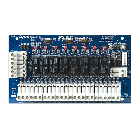
D+H TMA-1-D4-D12 User manual

TMA-1-D4-D12
X1
X6
X2
X5
X4
X3
99.827.69 1.0/05/18
Intended use
Functions:
• Module for connecting trigger peripheral devices
• Two independent lines for connecting a max. of 10 SHEV buttons and
30 re detectors per line (only detectors approved by D+H may be
used)
• Cables are monitored by the EM-L01 terminal module
• The SCS software can be used to congure the lines also as
user-programmable digital inputs and outputs
• Integrated LEDs to indicate a fault (yellow) and alarm (red)
• Connection using removable spring-type terminals
• Conductor cross-sections max. 1.5 mm² Flexible
• Dimensions WxHxD: 26x130x125 mm
• Installation on a 35 mm top hat rail in combination with an expansion
module socket
WARNING
This document is an extract from the instructions for use of the
CPS-M1 smoke and heat vent control panel and is only for informa-
tion purposes when retrotting.
For complete information on installation and opera-
tion, the CPS-M1 user manual (99.827.31) is available at
www.dh-partner.com or from your D+H partner.
Read all the safety information, instructions, images and technical data
provided with this product.
Failure to observe the following instructions can result in electric shock,
re and/or serious injury.
Keep all the safety information and instructions in a safe place for future
reference.
Safety information
• Only an authorised, electrically skilled person is allowed to connect the power
• Keep children away from the controller
• Only use in dry spaces
• Only intended for installation indoors
• Only use unaltered D+H original parts
Bestimmungsgemäße Verwendung
Funktionen:
• Modul zum Anschluss von Auslöseperipherie
• 2 unabhängige Linien (jeweils RM und RT) zum Anschluss von jeweils
max. 10 RWA-Tastern und 30 Brandmeldern (es dürfen nur von D+H
zugelassene Melder verwendet werden)
• Leitungsüberwachung erfolgt über das Endmodul EM-L01
• Die Linien können mit der SCS Software auch als frei programmierbare
digitale Ein und Ausgänge konguriert werden
• Integrierte LEDs für Störung (gelb) und Alarm (rot)
• Anschluss über abnehmbare Federzugklemmen
• Anschlussquerschnitte max. 1,5 mm² Flexibel
• Abmessungen BxHxT: 26x130x125 mm
• Montage auf 35 mm Hutschiene in Verbindung mit Erweiterungsmodul-
träger
WARNUNG
Dieses Dokument ist eine Auszug aus der Gebrauchsanleitung der
CPS-M1 RWA-Zentrale und dient nur zur Information bei Nachrüs-
tungen.
Für vollständige Informationen zur Installation und Betrieb
ist die Gebrauchsanleitung der CPS-M1 (99.827.25) unter
www.dh-partner.com oder bei Ihrem D+H Partner erhältlich.
Lesen Sie alle Sicherheitshinweise, Anweisungen, Bebilderungen und
technischen Daten, mit denen dieses Produkt versehen ist.
Versäumnisse bei der Einhaltung der nachfolgenden Anweisungen
können elektrischen Schlag, Brand und/oder schwere Verletzungen
verursachen.
Bewahren Sie alle Sicherheitshinweise und Anweisungen für die Zu-
kunft auf.
Sicherheitshinweise
• Anschluss darf nur durch eine autorisierte Elektrofachkraft erfolgen
• Kinder von der Steuerung fernhalten
• Nur in trockenen Räumen verwenden
• Nur für die Innenmontage geeignet
• Nur unveränderte D+H-Originalteile verwenden
Piktogrammerklärung
Zentrale O.K.
Störung
RWA - Alarm
Pictogram explanation
Control panel O.K.
Fault
SHEV alarm
EM-L01
Endmodule /
Terminal module

2/4 TMA-1-D4-D12 Deutsch / English 99.827.69 1.0/05/18Deutsch / English 99.827.69 1.0/05/18
Connection – TMAAnschluss – TMA
No. Name Description (as RM/RT lines)
X1.1 DO 2.3 No function
RT line 1
X1.2 DO 2.2 No function
X1.3 - Reference potential (do not connect to P-)
X1.4 DO 1.3 (S) Fault output (RT line 1), max. 50 mA
X1.5 DO 1.2 (A) Alarm output (RT line 1), max. 50 mA
X2.1 DO 1.1 (K) Monitoring output (RT line 1), max. 50 mA
X2.2 DI 1.1 (Z) Reset input (RT line 1)
X2.3 - Reference potential (do not connect to P-)
X2.4 LINIE 1 (T) RT line 1, max. 50 mA
X2.5 FE Functional earth
X3.1 DO 2.1 No function
RM line 1
X3.2 DI 2.1 No function / Reset input re alarm system
X3.3 - Reference potential (do not connect to P-)
X3.4 LINIE 2 (R) RM line 1, max. 50 mA
X3.5 FE Functional earth
X4.5 FE Functional earth
RM line 2
X4.4 LINIE 3 (R) RM line 2, max. 50 mA
X4.3 - Reference potential (do not connect to P-)
X4.2 DI 3.1 No function
X4.1 DO 3.1 No function
X5.5 FE Functional earth
RT line 2
X5.4 LINIE 4 (T) RT Line 2
X5.3 - Reference potential (do not connect to P-)
X5.2 DI 4.1 (Z) Reset input (RT line 2)
X5.1 DO 4.1 (K) Monitoring output (RT line 2), max. 50 mA
X6.5 DO 3.2 (A) Alarm output (RT line 2), max. 50 mA
X6.4 DO 3.3 (S) Fault output (RT line 2), max. 50 mA
X6.3 - Reference potential (do not connect to P-)
X6.2 DO 4.2 No function
X6.1 DO 4.3 No function
Nr. Name Beschreibung (als RM/RT-Linien)
X1.1 DO 2.3 keine Funktion
RT-Linie 1
X1.2 DO 2.2 keine Funktion
X1.3 - Bezugspotential (nicht mit P- verbinden)
X1.4 DO 1.3 (S) Störungsausgang (RT-Linie 1), max. 50 mA
X1.5 DO 1.2 (A) Alarmausgang (RT-Linie 1), max. 50 mA
X2.1 DO 1.1 (K) Kontrollausgang (RT-Linie 1), max. 50 mA
X2.2 DI 1.1 (Z) Reset-Eingang (RT-Linie 1)
X2.3 - Bezugspotential (nicht mit P- verbinden)
X2.4 LINIE 1 (T) RT-Linie 1, max. 50 mA
X2.5 FE Funktionserde
X3.1 DO 2.1 keine Funktion
RM-Linie 1
X3.2 DI 2.1 keine Funktion / Reset-Eingang BMA/BMZ
X3.3 - Bezugspotential (nicht mit P- verbinden)
X3.4 LINIE 2 (R) RM-Linie 1, max. 50 mA
X3.5 FE Funktionserde
X4.5 FE Funktionserde
RM-Linie 2
X4.4 LINIE 3 (R) RM-Linie 2, max. 50 mA
X4.3 - Bezugspotential (nicht mit P- verbinden)
X4.2 DI 3.1 keine Funktion
X4.1 DO 3.1 keine Funktion
X5.5 FE Funktionserde
RT-Linie 2
X5.4 LINIE 4 (T) RT-Linie 2
X5.3 - Bezugspotential (nicht mit P- verbinden)
X5.2 DI 4.1 (Z) Reset-Eingang (RT-Linie 2)
X5.1 DO 4.1 (K) Kontrollausgang (RT-Linie 2), max. 50 mA
X6.5 DO 3.2 (A) Alarmausgang (RT-Linie 2), max. 50 mA
X6.4 DO 3.3 (S) Störungsausgang (RT-Linie 2), max. 50 mA
X6.3 - Bezugspotential (nicht mit P- verbinden)
X6.2 DO 4.2 keine Funktion
X6.1 DO 4.3 keine Funktion
No. Name Description (as digital inputs/outputs)
X1.1 DO 2.3 Freely congurable digital output 2.3, max. 50 mA
X1.2 DO 2.2 Freely congurable digital output 2.2, max. 50 mA
X1.3 -Reference potential (do not connect to P-)
X1.4 DO 1.3 (S) Freely congurable digital output 1.3, max. 50 mA
X1.5 DO 1.2 (A) Freely congurable digital output 1.2, max. 50 mA
X2.1 DO 1.1 (K) Freely congurable digital output 1.1, max. 50 mA
X2.2 DI 1.1 (Z) Freely congurable digital input 1.1, 0 to 28 V, active - or +
X2.3 -Reference potential (do not connect to P-)
X2.4 LINIE 1 (T) No function
X2.5 FE Functional earth
X3.1 DO 2.1 Freely congurable digital output 2.1, max. 50 mA
X3.2 DI 2.1 Freely congurable digital input 2.1, 0 to 28 V, active - or +
X3.3 -Reference potential (do not connect to P-)
X3.4 LINIE 2 (R) No function
X3.5 FE Functional earth
X4.5 FE Functional earth
X4.4 LINIE 3 (R) No function
X4.3 -Reference potential (do not connect to P-)
X4.2 DI 3.1 Freely congurable digital input 3.1, 0 to 28 V, active - or +
X4.1 DO 3.1 Freely congurable digital output 3.1, max. 50 mA
X5.5 FE Functional earth
X5.4 LINIE 4 (T) No function
X5.3 -Reference potential (do not connect to P-)
X5.2 DI 4.1 (Z) Freely congurable digital input 4.1, 0 to 28 V, active - or +
X5.1 DO 4.1 (K) Freely congurable digital output 4.1, max. 50 mA
X6.5 DO 3.2 (A) Freely congurable digital output 3.2, max. 50 mA
X6.4 DO 3.3 (S) Freely congurable digital output 3.3, max. 50 mA
X6.3 -Reference potential (do not connect to P-)
X6.2 DO 4.2 Freely congurable digital output 4.2, max. 50 mA
X6.1 DO 4.3 Freely congurable digital output 4.3, max. 50 mA
Nr. Name
Beschreibung (als digitale Ein- bzw. Ausgänge)
X1.1 DO 2.3
frei kongurierbarer digitaler Ausgang 2.3, max. 50 mA
X1.2 DO 2.2
frei kongurierbarer digitaler Ausgang 2.2, max. 50 mA
X1.3 -
Bezugspotential (nicht mit P- verbinden)
X1.4 DO 1.3 (S)
frei kongurierbarer digitaler Ausgang 1.3, max. 50 mA
X1.5 DO 1.2 (A)
frei kongurierbarer digitaler Ausgang 1.2, max. 50 mA
X2.1 DO 1.1 (K)
frei kongurierbarer digitaler Ausgang 1.1, max. 50 mA
X2.2 DI 1.1 (Z)
frei kongurierbarer digitaler Eingang 1.1, 0 ... 28 V, - o. + aktiv
X2.3 -
Bezugspotential (nicht mit P- verbinden)
X2.4 LINIE 1 (T)
keine Funktion
X2.5 FE
Funktionserde
X3.1 DO 2.1
frei kongurierbarer digitaler Ausgang 2.1, max. 50 mA
X3.2 DI 2.1
frei kongurierbarer digitaler Eingang 2.1, 0 ... 28 V, - o. + aktiv
X3.3 -
Bezugspotential (nicht mit P- verbinden)
X3.4 LINIE 2 (R)
keine Funktion
X3.5 FE
Funktionserde
X4.5 FE
Funktionserde
X4.4 LINIE 3 (R)
keine Funktion
X4.3 -
Bezugspotential (nicht mit P- verbinden)
X4.2 DI 3.1
frei kongurierbarer digitaler Eingang 3.1, 0 ... 28 V, - o. + aktiv
X4.1 DO 3.1
frei kongurierbarer digitaler Ausgang 3.1, max. 50 mA
X5.5 FE
Funktionserde
X5.4 LINIE 4 (T)
keine Funktion
X5.3 -
Bezugspotential (nicht mit P- verbinden)
X5.2 DI 4.1 (Z)
frei kongurierbarer digitaler Eingang 4.1, 0 ... 28 V, - o. + aktiv
X5.1 DO 4.1 (K)
frei kongurierbarer digitaler Ausgang 4.1, max. 50 mA
X6.5 DO 3.2 (A)
frei kongurierbarer digitaler Ausgang 3.2, max. 50 mA
X6.4 DO 3.3 (S)
frei kongurierbarer digitaler Ausgang 3.3, max. 50 mA
X6.3 -
Bezugspotential (nicht mit P- verbinden)
X6.2 DO 4.2
frei kongurierbarer digitaler Ausgang 4.2, max. 50 mA
X6.1 DO 4.3
frei kongurierbarer digitaler Ausgang 4.3, max. 50 mA

3/4TMA-1-D4-D12
5432
1
5432
1
TMA-1-D4-D12
5
5
5
4
4
4
3
3
3
2 1
2 1
2 1
X1 X2 X3
X6 X5 X4
5432
1
–
A
S
n.c.
n.c.
–
T
K
FE
Z
R
–
FE
n.c.
n.c.
–
S
n.c.
n.c.
A
–
T
Z
K
FE
–
R
n.c.
n.c.
FE
–
R
23
5
–
R
23
5
23
5
T
–
4
Z
7
S
8
6
A
1
K
4
Z
7
S
6
A
1
K
23
5
T
–
8
5
–
R
23
bu rd
EM-L01
5
–
R
23
bu rd
EM-L01
283
5
–
T
n.c.
4
Z
7
S
6
A
1
K
OK
RT 45
4
Z
7
S
6
A
1
K
OK
283
5
–
T
n.c.
RT 45
OK
RT 45
OK
SD-O 371 / FD-T 271
SD-O 371 / FD-T 271
rdbu
EM-L01
rdbu
EM-L01
X1.1 X1.5
X2.1 X2.5
X3.1 X3.5
X4.5 X4.1
X5.5 X5.1
X6.5 X6.1
Deutsch / English99.827.69 1.0/05/18 Deutsch / English99.827.69 1.0/05/18
Anschluss – TMA (2 Linien) / Connection – TMA (2 lines)
RT-Linie 1 /
RT Line 1
RM-Linie 1 /
RM line 1
RT-Linie 2 /
RT Line 2
erster bis vorletzter Brandmelder /
First to second-last re detector
RM-Linie 2 /
RM line 2
letzter Brandmelder /
Last re detector

D+H Mechatronic AG
Georg-Sasse-Str. 28-32
22949 Ammersbek, Germany
Tel.: +4940-605 65 239
Fax: +4940-605 65 254
E-Mail: info@dh-partner.com
www.dh-partner.com
© 2018 D+H Mechatronic AG, Ammersbek
1
2
3
5432
1
5432
1
TMA-1-D4-D12
5
5
5
4
4
4
3
3
3
2 1
2 1
2 1
X1 X2 X3
X6 X5 X4
5432
1
–
A
S
n.c.
n.c.
–
T
K
FE
Z
R
–
FE
n.c.
n.c.
–
S
n.c.
n.c.
A
–
T
Z
K
FE
–
R
n.c.
n.c.
FE
283
5
–
T
n.c.
283
5
–
T
n.c.
4
Z
7
S
6
A
1
K
OK
23
5
RT 45
T
–
8
23
5
RT 45
T
–
4
Z
7
S
8
6
A
1
K
RT 45RT 45
OK
4
4
Z
Z
7
7
S
S
6
6
A
A
1
1
K
K
OK
rdbu
EM-L01
X1.1 X1.5
X2.1 X2.5
X3.1 X3.5
Technische Änderungen vorbehalten. /
Subject to technical modications. 99.827.69 1.0/05/18
General instructions for connection
• The connections, particularly the earth connections, may be connect-
ed to the respective associated PSM supply module and components
only.
• System voltage 24 V!
• Do not route cables together with high-voltage cables!
• When cables have a protective earth (green/ yellow) this must not be
used!
• No cross-ow of current may occur.
• Shields and additional cables must be connected separately.
• Mark cables and terminal boxes.
Einbau der Modulträger / Installation of the module sockets
Allgemeine Hinweise zum Anschluss
• Die Anschlüsse, insbesondere die Masseanschlüsse, dürfen nur mit
dem jeweiligen zugehörigen PSM-Versorgungsmodul und Kompo-
nenten verbunden werden.
• Systemspannung 24 V!
• Leitungen nicht mit Starkstromleitungen zusammen verlegen!
• Bei einer Leitung mit Schutzleiter (grün/ gelb) darf dieser nicht
verwendet werden!
• Es dürfen keine Querströme auftreten.
• Schirme und zusätzliche Leitungen sind separat anzuschließen.
• Kabel und Klemmdosen kennzeichnen.
Anschluss – TMA Parallelanaschluss RT / Connection – TMA parallel connection RT
RT-Linie /
RT line
Other D+H Control Unit manuals
Popular Control Unit manuals by other brands
Automation Controls Group
Automation Controls Group UniDrive SCC-3 Installation and troubleshooting guide
Eaton
Eaton DXE-EXT-SET Instruction leaflet
ICP DAS USA
ICP DAS USA CAN-8123 user manual
Quectel
Quectel BG772A-GL Hardware design
Afag
Afag SE-Power FSM 2.0 MOV Short description
axing
axing SKF 40-00 Operation instructions

