Dr.Meter IR-60 User manual

Dr. meter Non-Contact Infrared Thermometer
Model: IR-60
User Manual
Safety Information
Please read this user manual carefully before using the thermometer.
Do not clean the thermometer with any solvents.
Safety symbols:
Important notices against hazards
Compliant with European CE safety directive
This thermometer complies with the standards provided below:
EN61326-1
EN60825-1
Warning!
Do not point the thermometer’s laser at anyone’s eyes, or let the beam strike the eyes from
any reflective surface.
Important Notices
When introducing the thermometer to a new environment, allow the unit 30 minutes to
adjust to temperature changes before usage. Temperature measurement can only resume
when the meter’s temperature is consistent with the new environment temperature.
Keep the unit away from EMF (electro-magnetic fields) and induction heaters.
Do not point the unit’s laser directly at eyes.
Do not leave the unit on or near objects with high temperatures.
Do not use this unit in areas where explosive gas, steam, dust and smog are present to
ensure uninterrupted measurement results.
Keep the thermometer’s lens cone free from frost, oil and dirt to ensure accurate
temperature readings.
Product Illustration

1Alarm indicator
2LCD Display
3Laser /numeric decrease button
4Mode button
5Backlight/numeric increase button
6Infrared sensor
7Laser indicator
8Backlight
9Trigger button
10 Battery cover
1Primary display panel: displays measured temperature.
2Functional indication: displays Max, HAL(high alarm level), LAL(low alarm level),
E(emissivity)
3Secondary display panel
4Fahrenheit unit
5Celsius unit
6Low battery indicator
7Temperature measurement indicator
8Data hold
9Laser on indicator (indicates that the laser is on)

Operating the Themometer
1. Set the upper/lower limit values for alarms
Hold the trigger and mode button simultaneously to adjust the upper/lower limits set
for the alarm. The functional indication display will show the HAL/LAL options, and
the secondary display will show the upper/lower limits for the alarm. Press ▲/▼key
to increase or decrease the alarm value. A long hold on the ▲/▼key will speed up
the increase or decrease functions for the set value.
The default upper limit alarm value for this instrument is 5℃, and the default lower
limit value is -5℃.
2. Set the emissivity
Press the trigger button to power up the device. The functional indication area will
display the Esymbol. Press the mode button to set the emissivity for the instrument.
The functional indication area will display the symbol. Press the ▲/▼buttons to
increase or decrease the emissivity value. A long hold on the ▲/▼key will speed up
the increase or decrease functions in the set value.
3. Set the temperature scale unit
Press the mode button for 2s to switch the temperature scale unit between Fahrenheit
and Celsius.

4. Enable/disable laser
Press the button to enable or disable laser. The instrument will display the
symbol on the display panel to indicate whether the laser is switched on or off
5. Turn on/off backlight
Press the button to turn on or off the display screen’s backlight.
6. Non-contact temperature measurement
Direct the thermometer at an object and hold the trigger button to carry out continuous
temperature measurement. After the temperature reading has stabilized, release the
trigger button to hold a temperature reading.
Upon pressing the trigger button,, the instrument's secondary display panel will first
show the set emissivity, and then display the maximum temperature measured .
When the measured value is greater than the ambient temperature + HAL value,or
the measured value is less than the ambient temperature + LAL value, the red LED
indicator of the instrument will turn on. Otherwise, the green indicator will turn on.
7. Proportion between the distance from probe to object and the
diameter of the object to be measured (D:S)
The thermometer has a specific field of view, as shown in the diagram below:

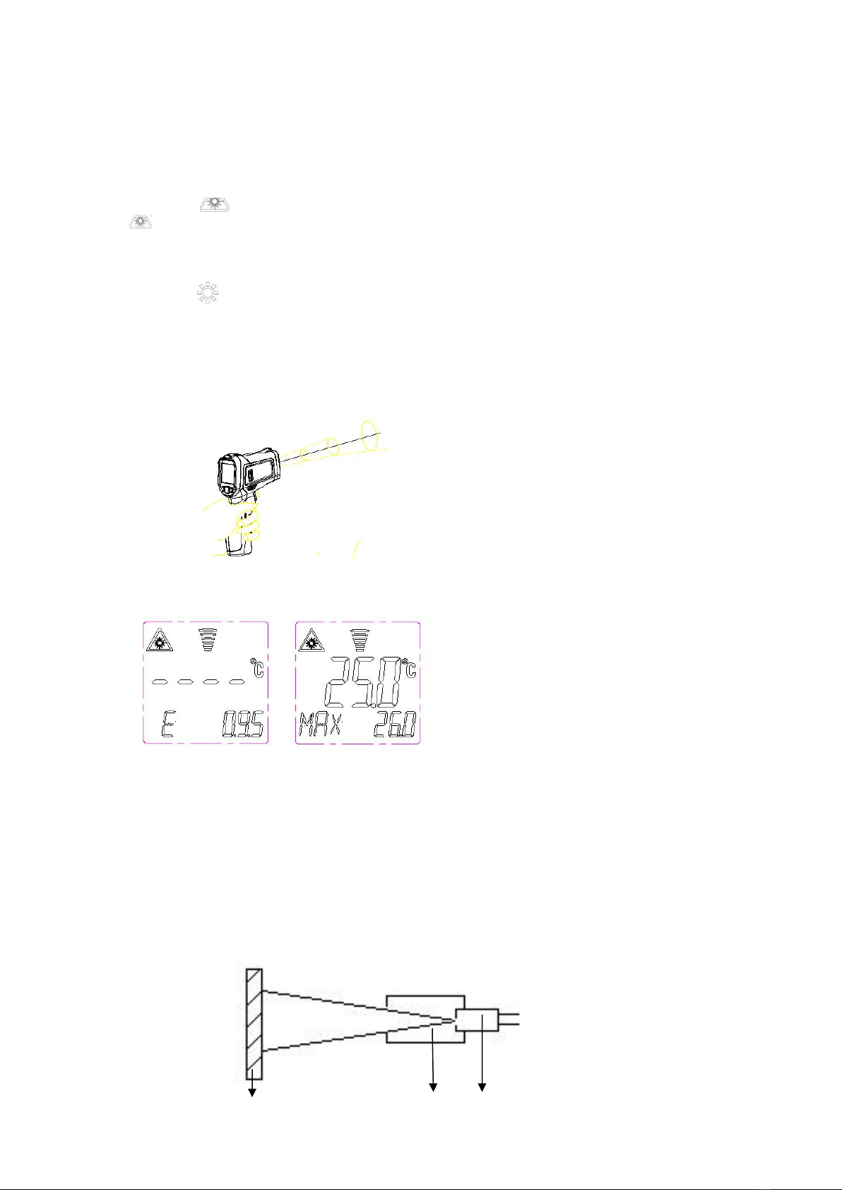
Ensure that the object to be measured is placed within the field of view to get an
accurate temperature reading. If the object is located outside the field, the
thermometer will not be able to detect the object’s temperature. The size of the object
is proportionate to the distance required – the bigger the object is in size, the further it
has to be placed away from the thermometer. Inversely, the smaller the object is in
size, the nearer it has to be placed to the thermometer for accurate measurement. As
the distance (D) from the object increases, the spot size (S) of the area measured by
the unit increases, and has a ratio of 12:1, as shown in the diagram below:
When the laser mode is on, the thermometer will project a circle of infrared dots on the target
surface. The temperature reading displayed on the thermometer is read from the area inside
the circle. While measuring an object, the instrument will emit an indicative ring. The
measured temperature of the surface is the internal temperature of the ring.
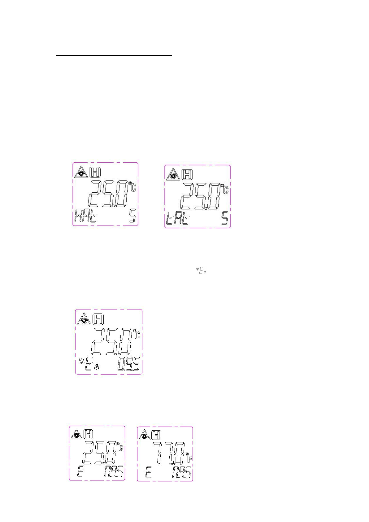
8. Emissivity
Emissivity refers to the ability of an object to emit infrared energy. Emissivity is
determined by the object’s composition and surface area. The emissivity of most
organic materials or oxidized surfaces of metals falls within the range of 0.85~0.98.
The default emissivity of this thermometer is 0.95. The thermometer’s emissivity
should be set to be consistent with that of the object to be measured..
The diagram provided below is a reference table for the emissivity of various surfaces:
Surface measured
Emissivity
Aluminum Metal
Oxidized
0.2~0.4
A3003 Alloy
Oxidized
0.3
A3003 Alloy Rough
0.1~0.3
Brass
Polished
0.3
Oxidized
0.5
Copper
Oxidized
0.4~0.8
Electronic terminal
Board
0.6
Hastelloy
0.3~0.8
Chromium-Nickel-Iron Alloy
Oxidized
0.7~0.95
Sandblast
0.3~0.6
The object to
be measured
photosensitive
element
Lens
cone

Electro-Polished
0.15
Iron
Oxidized
0.5~0.9
Rusted
0.5~0.7
Iron(Cast)
Oxidized
0.6~0.95
Non-oxidized
0.2
Melt & cast
0.2~0.3
Iron(Forged) Passivated
0.9
Lead
Rough
0.4
Oxidized
0.2~0.6
Mo Oxidized
0.2~0.6
Nickel Oxidized
0.2~0.5
Platinum Black
0.9
Steel
Cold rolled
0.7~0.9
Polished plate
0.4~0.6
Polished plate
0.1
Zinc
Oxidized
0.1
Asbestos
0.95
Asphalt
0.95
Basalt stone
0.7
Carbon
0.8~0.9
Non-oxidized
0.7~0.8
Graphite
0.9
Silicon Carbide
0.95
Clay
0.95
Concrete
0.95
Fabric
0.95
Glass plate
0.85
Sand-gravel
0.95
Gypsum
0.8~0.95
Ice
0.98
Limestone
0.98
Paper
0.95
plastic
0.95
Soil
0.9~0.98
Water
0.93
Wood (natural)
0.9~0.95
9. Battery replacement
When the battery's power is low, the top right corner will display .
To replace the battery, open the battery cover and replace the old battery with a new
9V battery as shown in the illustration below:

Specifications
Temperature range
-50℃~ 550℃(-58℉~ 1022℉)
Accuracy
0℃~550℃(32℉~1022℉): ±(1.5% reading + 2℃)
-50℃~0℃(-58℉~32℉): ±3℃
LCD
Color LCD
D:S
12:1
Spectral response
8-14 um
Laser
<1mW /630-670nm Level 2
Response time
<0.5S
Automatic shutdown
15S
Operating temperature
0℃~40℃
Storage temperature
-10℃~ 60℃
Power
9V 6F22 battery
Table of contents