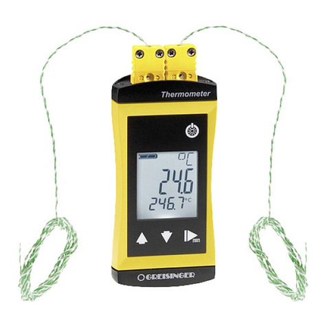
Chino IR-FA Series User manual

INST.No.INE-378-P9CE
IR-FA Series
Fiber Type Radiation
Thermometer
Model : IR-FAI,IR-FAS,IR-FAQH,
IR-FAQI,IR-FAQS
Always keep this instruction manual with the
unit.
Please be sure to deliver this instruction manual
with the unit to the end user.

INST.No.INE-378-P9CE
- C1 -
Request and Notices
◆Request to the operator of the thermometer
This instruction manual describes the maintenance of the thermometer, too.
Keep this instruction manual with the thermometer.
If you have unclear points or need technical assistance, please contact your sales agent of
CHINO Corporation.
Notices
1. The information in this manual is subject to change without notice and does not
represent a commitment on the part of CHINO Corporation.
2. No part of this manual may be reproduced or transmitted in any form or by any means,
electronic or mechanical, including photocopying and recording, for any purpose other
than the purchaser's personal use without permission of CHINO Corporation.
3. CHINO Corporation shall not be liable for any operation results.
Please read this instruction manual for using the thermometer
correctly and safely.

INST.No.INE-378-P9CE
- C2 -
Preface
To use the thermometer correctly and safely, please keep the following safety measures for the operation
and storage of the thermometer.
1. Working conditions and environment
∙The working temperature range of the thermometer is 0 to 50 °C. (No dew condensation)
∙Do not use the thermometer in dusty places, etc. Remove the dust after using it.
∙Be careful not to give vibration or impact to the thermometer. Install the thermometer as far as possible
from an inductive oscillator or electric power line.
∙The fiber optics is consisted of the single-core quartz fiber and the sheath. Two kinds of the sheath are
available.
∙The maximum working temperature of the fiber optic assembly is 150ºC.
2. Storage
∙Do not store the thermometer in hot and humid places.
∙Two types of the fiber optics are available, one is the single-core quarts optical fiber covered by a
heat-resistant sheath with glass wool over braided, and the other is the single-core quarts optical fiber
covered by a heat-resistant material with the glass wool over braided and, and further covered by
flexible metal tube sheath. For the storage of the fiber optics, keep it with the bending radius larger than
the allowable value (R: about 100mm).
∙Make sure to connects the optical connectors of the fiber optics to the optical connectors of the
thermometer and the lens assembly with the proper key slit position. Don’t crack the fiber optics sheath
or make it dirty. (Ref. [4.3 Cautions on installation/maintenance of fiber optics])
∙For failures of the thermometer, don’t overhaul it by yourself, and contact your sales agent of CHINO
Corporation.
3. Symbols in this instruction manual
The symbols shown below are used depending on important degrees for using the thermometer safely and
avoiding unexpected situations.
Important
degree Symbols Contents
1This symbol is attached to a title for the sentence with .
2For avoiding dangerous accidents (may cause death or serious injury) like
as electrical shock, fires, or troubles/damages of the thermometer.
3For avoiding injury or in physical damage to the thermometer.
4Information that we suggest to read carefully.
5Information that you can use as a reference.
Warning
Remarks
Caution
Warning
The thermometer has been calibrated with a fiber optic assembly consisted of a fiber optics and a lens
assembly. Connect the correct fiber optic assembly to the thermometer.
(Ref. [3.1.1 Thermometer view] and [3.3 Fiber optics])
The fiber optics has a direction of the thermometer side and the lens assembly side, and the
thermometer has been calibrated with the correct directional fiber optics. If you connect the fiber optics
with the opposite direction to the thermometer, you will have an indication error.
(Ref. [3.3 Fiber optics])
!
Reference
!

INST.No.INE-378-P9CE
- C3 -
Warnings and Cautions
◆Please use the thermometer correctly by keeping the following items.
In addition, please read this instruction manual carefully and keep it at the place where
you can access easily.
The mark indicates prohibited operations.
Warning (May cause death or serious injury)
Don’t use the fiber optic assembly in places over 150 ºC.
Don’t operate the thermometer in places where combustible or volatile gas is existed.
It is extremely dangerous to use the thermometer in such environment.
When connecting power to the power terminals, make sure that all mains is turned off to
prevent an electric shock.
Don’t use the thermometer if it was broken, smoking or nasty smelling.
These may cause fire. For such abnormal condition, turn off the power switch at once
and contact your sales agent of CHINO Corporation.
Laser may damage your eyes. Don’t stare into a laser beam. Make sure to target the laser
when you want the decide the center of the measuring object only and to go off it after
the center of the measuring object is decided.
Never take the thermometer apart or convert it.
These may cause trouble and danger.
Caution (May cause injury or physical damage)
The thermometer has been calibrated with the fiber optic assembly. When you use several
thermometers, make sure that the combination of the thermometer and the fiber optic
assembly is correct. (Ref. [3.1.1 Thermometer view] and [3.3 Fiber optics]
The maximum working temperature of the fiber optic assembly is 150ºC. Use it under this
maximum working temperature. (Ref. [3.2 Fiber optics assembly])
Be careful not to give vibration or impact to the thermometer. Install the thermometer by
keeping it as far as possible from an inductive oscillator or electric power line.
Avoid the unnecessary detachment and attachment of the fiber optics.
Make sure not to tension the fiber optics or bend its joint to the optical connector.
(Strong tension or too bending the fiber optics may cause damage of the optical fiber.)
The fiber optics can be bent but make sure to use it with the bending radius larger than its
allowable value (R: about 100mm). (Ref to [4.3 Cautions on installation/maintenance of fiber
optics])
When connecting the optical connectors of the fiber optics to the optical connectors of the
thermometer and the lens assembly, make sure to turn them with your hand. (Don’t turn them
by using a tool like as pliers.)
Don’t overhaul or modify the thermometer. These may cause trouble and danger.
Read the entire contents in this instruction manual to have the thermometer function perfectly.
!
!
!
!
!
!
!
!
!
!
!
!
!
!
!
!
!

INST.No.INE-378-P9CE
- C4 -
CONTENTS
1. Introduction.................................................... 1
1.1 General..................................................... 1
2. Model ............................................................ 2
2.1 Model........................................................ 2
2.2 Standard temperature range ..................... 3
2.3 System configuration................................. 3
3. Names and functions of component parts...... 4
3.1 Thermometer............................................ 4
3.1.1 Thermometer view.................................... 4
3.1.2 Function key and digital display................ 5
3.1.3 Functions keys*1...................................... 5
3.1.4 Markers .................................................... 5
3.2 Fiber optics assembly ............................... 6
3.2.1 General-purpose type lens assembly........ 6
3.2.2 Lens assembly with air purge case........... 6
3.3 Fiber optics............................................... 7
4. Installation..................................................... 8
4.1 Installation of thermometer........................ 8
4.1.1 Using DIN rail ........................................... 8
4.1.2 Using mounting plate................................ 8
4.1.3 Installation/removal................................... 9
4.1.3-1 Installation............................................. 9
4.1.3-2 Removal................................................ 9
4.2 Installation of lens assembly ................... 10
4.2.1 General-purpose type lens assembly...... 10
4.2.2 Lens assembly with air purge case......... 10
4.2.3 Spot size and measuring distance
(General-purpose type lens assembly,
Lens assembly with air purge case).....11
4.3 Cautions on installation
/maintenance of fiber optics...... 12
4.4 Confirmation of view field........................... 12
5. Connections and wirings.............................. 13
5.1 Connections and wirings......................... 13
5.1.1 Connections of
fiber optics assembly to thermometer..... 13
5.1.2 Wirings to power terminals...................... 14
5.1.3 Wirings to ground terminals.................... 14
5.1.4 Wirings to receiving instruments............. 14
6. Operation .................................................... 15
6.1 Digital display.......................................... 15
6.2 Parameter programming
/selection (Operating mode)........ 15
6.3 Parameter programming
/selection (Engineering mode) .... 16
6.4 Operating Mode ...................................... 17
6.4.1 Emissivity programming.......................... 17
6.4.2 Automatic emissivity calculation.............. 17
6.4.2-1 Automatic emissivity calculation(Internal )
:Input of reference temperature...... 17
6.4.2-2 Automatic emissivity calculation
(External : IR-FA5 only)
: Selection of external programming.... 18
6.4.3 Signal modulation mode selection........... 18
6.4.4 Modulation degree programming ............ 19
6.4.4-1 Modulation time
constant programming ....... 19
6.4.4-2 Damping degree selection................... 19
6.4.5Alarm programming ................................ 20
6.4.5-1 Alarm type selection............................. 20
6.4.5-2 Alarm set-point..................................... 20
6.5 Engineering mode................................... 21
6.5.1 Analog output scaling programming........ 21
6.5.1-1 Analog output minimum value
programming…"OutL" ....... 21
6.5.1-2 Analog output minimum value
programming…"OutH"....... 21
6.5.2 Analog dummy output programming ....... 22
6.5.3 Hold functions
(Hold disable, sample hold, peak hold)
selection ........ 23
6.5.3-1 Hold function type selection................. 23
6.5.3-2 Peak hold reset type selection............. 24
6.5.3-3 Peak hold reset time programming...... 25
6.5.4 Measurement unit selection.................... 25
6.5.5 Contact output item selection.................. 26
6.5.6 Automatic emissivity calculation
type selection.......... 27
6.5.7 Zero/span adjustments ........................... 28
6.5.7-1 Zero / span adjustments
executive choice.............. 28
6.5.7-2 “Zero” side adjustment
…Adjustment by furnace temperature
at zero side...... 28
6.5.7-3 “Span” side adjustment
…Adjustment by furnace temperature
at span side ... 29
!
!
!

INST.No.INE-378-P9CE
- C5 -
6.5.8 Analog output correction programming ... 30
6.5.8-1 Programming of number
of analog output correction data
(number of knee-point)........ 30
6.5.8-2 Programming of analog output
correction data No...... 30
6.5.8-3 Entering of data before analog
output correction........ 31
6.5.8-4 Entering of data after analog
output correction........ 31
6.5.8-5 Selection of analog output
correction for programming item ......... 32
6.5.9 Analog input programming
(for IR-FA5 with option analog input)... 32
6.5.9-1 Selection of analog input items............ 33
6.5.9-2 Emissivity scaling for remote
emissivity programming............ 34
6.5.9-3 Temperature scaling for automatic
emissivity calculation................ 35
6.5.10 Communications programming
(for IR-FAS with optional
communications) ........... 36
6.5.10-1 Address programming ....................... 36
6.5.10-2 Communication speed selection........ 36
6.6 Key lock.................................................. 37
6.7 Laser targeting(Option)....................... 38
6.8 Self-diagnostic function........................... 39
6.9 Overflow/underflow................................. 40
6.10 Under flow display for two-color type
radiation thermometer only: “CLP” ........ 40
7. Maintenance and check............................... 41
7.1 Periodical checking ................................. 41
7.2 Trouble shooting...................................... 41
7.2.1 Measuring value not displayed
or displayed lower............ 41
7.2.2 Measuring value displayed higher........... 41
7.2.3 Display fluctuated ................................... 42
8. Reference.................................................... 43
8.1 Emissivity table ....................................... 43
8.1.1 Emissivity table (= 0.65µm).................. 43
8.1.2 Emissivity table (= 0.9µm)..................... 44
8.1.3 Emissivity table (= 1.55µm)................... 44
9. General Specifications................................. 45
9.1 Thermometer .......................................... 45
9.2 Lens assembly........................................ 46
9.3 Fiber optics ............................................. 46
9.4 Standard temperature range.................... 46
10. List of starting up modes............................ 47
10.1 Starting up modes ................................. 47
10.2 Screens................................................. 47
10.3 Parameter programming/selection......... 48
10.3.1 Parameter programming
/selection (operating mode) ........ 48
10.3.2 Parameter programming
/selection (engineering mode).... 49
Laser Safety
This Model is certified as a class laser product under the U.S. Department of Health and
Human Services (DHHS) Radiation Performance standard according to the Radiation
Control for Health and Safety Act of 1968. This means that this Model does not produce
hazardous laser radiation.
CDRH Regulation
The Center for Devices and Radiological Health (CDRH) for the U.S. Food and Drug
Administration implement regulations for laser products August 2, 1976. These regulations
apply to laser products manufactures from August 1, 1976. Compliance is mandatory for
products marketed in the United States.
Note: Make sure to read the items with the mark of the articles of are included.
Warning
CONTENT
S
!
!

INST.No.INE-378-P9CE
- 1 -
1. Introduction
1.1 General
In the IR-FA series fiber optic radiation thermometers, four kinds of models, single color type Models
IR-FAI and IR-FAS and two-color type model IR-FAQ and IR-FAQI, and IR-FAQH, and IR-FAQS are
available.
The thermometer, the fiber optics, and the lens assembly are connected through optical connectors. The
radiation energy collected through the lens is transmitted to the element through the optical fiber and is
converted into an electrical signal. The element output is digitally converted and processed through
emissivity compensation, linearizer, and modulation. The standardized final output is 4 to 20mA DC.
Functional keys make programming or selection of emissivity, signal modulation and alarm function easy.
Two types of the lens assembly are available, a universal type, and the lens assembly with a viewfinder.
An air purge case is available for the universal type lens assembly.

INST.No.INE-378-P9CE
- 2 -
●Two-colors type thermometer *2
IR-FAQ Element
QH: 2-colors hybrid element
QI : 2-colors InGaAs/InGaAs
QS : 2-colors Si *1
External input/output(option).
N : None
S : Communications
inter face RS-485
5 : External analog input
(4 to 20 mA)
Laser targeting (Optional).
N : Not provided
L : Laser built-in *3
2. Model
2.1 Model
●Single-color type thermometer *2
IR-FA Element
I : InGaAs
S : Si
External input/output. (option)
N : None
S : Communications inter face RS-485
5 : External analog input
(4 to 20 m A)
Laser targeting (Option).
N : Not provided
L : Laser built-in *3
High-sensitivity type (Option)
N : Standard type
U : High sensitivity type *1
*1: Out of CE marking.
*2: Cable length is less than 30m in room.
*3: When the lens assembly with a viewfinder is used, the laser spotting unit or the laser targeting
function on the main unit can not be used along with it.
●General-purpose type lens assembly
IR-FL Spot size/measuring distance
0: 1mm/100mm
1: 12mm/1000mm
2: 5mm/500mm
3: 2mm/200mm
4: 4mm/200mm
5: 5mm/150mm
6: 20mm/600mm
8: 8mm/1000mm
Air purge case
N: None
A: Provided
Fiber sheath
H: Without metal protective tube.
N: With metal protective tube.
Fiber length: Length (m) to be specified.
(Standard length: 2m,
up to 50m up on requests.)
●Lens assembly with a viewfinder
IR-FF1 (5at500) IR-FF2 (φ4at370)
Measuring
distance Measuring
diameter Measuring
distance Measuring
diameter
L1: 400 D1:
7L1: 270 D1:
7
L2: 500 D2:
5L2: 370 D2:
4
L3: 600 D3:
9L3: 470 D3:
9
IR-FF3(φ10at1000)
Measuring
distance Measuring
diameter
L1:800 D1:11
L1:1000 D1:10
L3:1200 D1:15
(Ref [9.3 Fiber optics])
EN61326-1 ClassA
-marking

INST.No.INE-378-P9CE
- 3 -
IR-FA
SERIES
SEL ENT
IR-FAQHSL V2 .40 700 *2000 ℃ FA00 6Q002
IR-FL8NN04 00291-04
OUT
P- S+ S - D O DI COM
24V DC
P
+
Digital indicator
Recorder
Controller
4 to 20mA
DC
Main unit
Contact output
Power supply
24VDC
Beam-condensing
assembly
General-purpose type
beam-condensing assembly
Beam-condensing assembly
with air purge
2.2 Standard temperature range
●Single-color type ●Two-colors type
Model Measuring range Lens assembly
IR-FAI
150 to 450°C*
200 to 700°C
250 to 1000°C
300 to 1300°C
IR-FL5
IR-FL6
250 to 1000°C
300 to 1300°C
350 to 1600°C
IR-FL0,IR-FL1
IR-FL2,IR-FL3
IR-FL4,IR-FL8
IR-FAS
400 to 900°C*
500 to 1200°C
600 to 1800°C
700 to 2400°C
IR-FL5
IR-FL6
600 to 1800°C
700 to 2400°C
800 to 3000°C
IR-FL0,IR-FL1
IR-FL2,IR-FL3
IR-FL4,IR-FL8
*Mark is for model IR-FA□NU only.
(Optional laser targeting is not available.)
2.3 System configuration
*Mark is excluded from CE marking
Model Measuring range Lens assembly
IR-FAQH
600 to 1500°C
700 to 2000°C
800 to 2400°C
1000 to 3000°C
IR-FL0,IR-FL1
IR-FL2,IR-FL3
IR-FL4,IR-FL5
IR-FL6,IR-FL8
IR-FAQI
300 to 1200°C
400 to 1500°C IR-FL5
IR-FL6
400 to 1500°C IR-FL0,IR-FL1
IR-FL2,IR-FL3
IR-FL4
450 to 1500°C IR-FL8
IR-FAQS
800~1600°C
1000~2000°C
IR-FL0,IR-FL1
IR-FL2,IR-FL3
IR-FL4,IR-FL5,
IR-FL6
850~1600°C
1000~2000°C IR-FL8
Fiber optic assembly Thermometer Instruments
Caution
Please do so that laser is lighted only at the time of the confirmation of the measurement position.
Caution
*
*
Caution
In illumination condition ( ) of the laser light is irradiated from the place. Please never look it.
Caution
*

INST.No.INE-378-P9CE
- 4 -
3. Names and functions of component parts
3.1 Thermometer
The thermometer consists of a (1) Digital display, (2) Function keys, (3) Optical connector,
(4) Input/Output terminals, and (5) DIN rail stopper.
The output signal from the thermometer is 4mA to 20mA DC and isolated.
Error alarm higher or lower is available by a contact output.
You can reset “peak hold” or “sample hold” by a contact input.
The emissivity is set by the function keys and displayed digitally.
The emissivity remote setting and the automatic emissivity processing are available by an optional
function of "with external analog input".
3.1.1 Thermometer view
(1)Digital
display
Main display:4-digit LCD.
Sub display: 4-digit LCD.
Status markers: Alarm display.
Sub markers: Status display.
Temperature unit: ºC or ºF
Ref. to [3.1.2 Function key and
Digital display.],
[3.1.4 Markers.]
(2)Function
keys These five keys are used for the program of
parameters.
Ref. to [3.1.3 Function keys]
Ref. to [6.Operation]
(3)Optical
connector The optical connector is for the connection
with the optic assembly. Ref. [5.1.1 Connection of fiber
optic assembly to thermometer.]
(4)Input-Output
terminal 10P
The input/output terminals are for wiring 24V
DC power supply, ground, output signal,
contact input/output, and options. Ref. [5.1 Connections and wirings]
(5)DIN rail
stopper
DIN rail stopper is used to mount the
thermometer to a DIN rail or to mount the
thermometer by a mounting plate. Ref. [4.1.3 Installation/removal.]
(3)Optic
al
connector
(4)Input
-
Output
terminal 10P
IR-FA SERIES
SEL ENT
IR-FAINNL V2.40 300*1300℃ FA019I006
IR-FL6AN07 01686-07
24V DC OUT
P+ P - S + S- DO DI COM
(1)Digital display
(2)Function
Keys
(5)DIN rail stopper
IR-FAINNL V□. □□ 300*1300℃FA052I002
IR-FL6AN07 01686-07(*)
Fiber model Fiber Serial No.
For model
IR-FALand
IR
-
FAQ
L
Alarm label
[*Serial No. Label for thermometer]
Model
Software
version
Temperature
range
Serial No.
SEL ENT
* This label indicates the serial number of the fiber optic assembly to be combined.
Use the fiber optic assembly with the same serial number. (Ref. [3.3 Fiber optics])
Caution

INST.No.INE-378-P9CE
- 5 -
3.1.2 Function key and digital display
3.1.3 Functions keys*1
Keys Functions Indications
(1): Select key Used to select a parameter menu in the operating mode or the
engineering mode.
(2): Next key Used to select a parameter in the parameter selection mode or to
shift a digit for numeric entries to the right in the parameters
programming mode.
(3): Up key
(4): Down key Used to select a parameter in the parameter selection mode or to
scroll numeric characters in the parameters programming mode.
(5): Entry key Used to store the selected or programmed parameter.
3.1.4 Markers
Main display*2 :Displays the measured value in the measurement mode, or a parameter in the parameter
selection or programming mode.
Sub display*3 :Displays the parameter menu selected by SEL key in the measurement mode, or a
parameter menu in the parameter selection or programming mode.
Names Markers Major functions Indications
(6) Main marker
Tb Not used “Tb”
CONT Not used “CONT”
MEM Not used “MEM”
PEAK Not used “PEAK”
(7) Status marker AL Will light when the low alarm is activated. “AL”
AH Will light when the high alarm is activated. “AH”
(8) Temperature
unit
CWill light when a temperature is displayed in
Celsius. “C”
FWill light when a temperature is displayed in
Fahrenheit. “F”
(9) Sub marker (r)
Will light when the sub display shows an
emissivity (emissivity ratio).
(emissivity) is for single-color type and
r(emissivity ratio) is for two colors type.
“”or “r”
SEL
ENT
Tb CONT MEM PEAK
AL AH
C
F
ε
SEL
ENT
Function keys *1
(1) (2) (3) (4) (5)
Sub display *3
Main display *2
(6)Main marker
(7)Status marker
(9)Sub marker
(8)Temperature
unit

INST.No.INE-378-P9CE
- 6 -
L1 57.5
10
(2)Mounting screw (1)Optical connector
7.5
Ø
3.2 Fiber optics assembly
3.2.1 General-purpose type lens assembly (Model :IR- FL□N□□□)
(1) Optical connector: Used to connect the fiber optics.
(2) Mounting screw: Used to directly mount the lens assembly to an air purge case or other units.
Lens assembly type 0,1,2,3 4 5 6 8
L1 35 15 10 10.5 45
3.2.2 Lens assembly with air purge case (Model :IR- FL□A□□□)
(1) Optical connector: Used to connect with the fiber optics.
(2) Air purge coupler: Used to purge dust particles in front of the lens by air.
(3) Mounting hole (ø4.5mm): Used to fix the case by using 2 pieces of M4 screws.
Lens assembly type 0,1,2,3 4 5 6 8
L2 10 30 35 34.5 0
(1) Optical connector
(2) Air purge coupler
(3) Mounting hole (ø4.5mm)
L2
Caution
For mounting the lens assembly with the air purge case, connect the fiber optics after
mounting the air purge case.
For removing, disconnect the fiber optics and then remove the air purge case.
If the air purge case being connected with the fiber optics is mounted or removed, the
fiber optics may be damaged by the weight of the air purge case.
The maximum working temperature of the fiber optics assembly is 150ºC.
Don’t use it in places higher than 150ºC.
Warning
!

INST.No.INE-378-P9CE
- 7 -
3.3 Fiber optics
The fiber optics is consisted of the single-core quartz fiber and two optical connectors at both ends. Two
types of the sheath are available (Ref. [9.3 Fiber optics] in [9. General specifications])
1) Fiber optics covered by heat-resistive material with glass wool over braided. The maximum working
temperature is 150°C.
(Model: IR-FLH)
2) Fiber optics covered by heat-resistive material with glass wool over braided, and further covered by
metal flexible tube sheath. The maximum working temperature is 150°C.
(Model: IR-FLN)
[Labels and direction of fiber optics]
CHINO label side: Connect to the lens assembly
Fiber optics serial no. label side: Connect to the thermometer
Caution
The maximum working temperature of the fiber optic assembly is 150ºC.
Don’t use it in places higher than 150ºC.
When adding strong power to the neighborhood of an arrow mark, fiber optics is
damaged. Don’t add the strong power of 40 N over.
Caution
01686-07
02686-01
CHINO
*
*
CHINO
[
IR
-
FL
H
: Without metal protective tube]
Connect to lens assembly
CHINO’s label
Optical connector
Fib
er (Quats fiber)
Fiber
’
s serial no. label
CHINO’s label
Connect to thermometer
[
IR
-
FL
N
: Without metal protective tube]
Optical connector
Fiber (Quats fiber)
Connect to lens assembly
C
onnect to thermometer
Fiber
’
s serial no. la
bel
Notice
Notice
!
Warning
The fiber optics has a direction of the thermometer side and the lens assembly side,
and the thermometer has been calibrated with the correct directional fiber optics.
If you connect the fiber optics with the opposite direction to the thermometer, you
will have an indication error.
By referring to the [Labels and direction of fiber optics] shown below, connect the
fiber optics with the proper direction.
Reference

INST.No.INE-378-P9CE
- 8 -
4. Installation
4.1 Installation of thermometer
Install the thermometer to place the fiber optics downward.
However, the installation is optional on the performance of the thermometer.
4.1.1 Using DIN rail
4.1.2 Using mounting plate
Fix the main unit securely by using two M4 screws.
49.6
82
66.7
2-
±0.2
4
7.3
24 7
1.5
35
1.5
66.7
45.0 10.5
2-M4
Ø
5.0
ENT
SEL
IR-FA
SERIES
P+ P- S + S- D O DI CO M
24VDC O U T
90
IR-FAQHSL V2.40 700 *2000 ℃ FA00 6Q002
IR-FL8NN04 002 91-04
90
Input/output
terminals (10P) Fiber optics
DIN rail
DIN rail stopper
60
45

INST.No.INE-378-P9CE
- 9 -
4.1.3 Installation/removal
4.1.3-1 Installation
1) Fix a DIN rail or the mounting plate on the wall.
(Fix the mounting plate with the protruding part upward.)
2) Pull the DIN rail stopper downward.
3) Hook the ○
A of the thermometer to the upper side of
the DIN rail, and push the thermometer toward to ○
B .
4) Raise the DIN rail stopper upward with minus driver to
complete the installation of the thermometer.
4.1.3-2 Removal
1) Remove the thermometer by pulling the DIN rail stopper
downward with plugging the minus driver into the ○
C .
DIN rail stopper
C
DIN rail (35mm width)
or mounting plate
DIN rail stopper
B
A
Thermometer Wall etc
Protruding part
(For mounting plate)
Don’t use the thermometer in the following places.
1) Dusty place or a corrosive gas atmosphere.
2) Places where noisy and static electric are existed.
3) Places where the ambient temperature is higher than 50°C or lower than 0°C.
4) Places where the ambient temperature changes abruptly, or high humid places.
5) Places where an inductive oscillator or electric power line are existed near side.
6) Places where there are mechanical vibrations and impacts.
7) Places where combustible or volatile gas is existed.
Caution

INST.No.INE-378-P9CE
- 10 -
4.2 Installation of lens assembly
4.2.1 General-purpose type lens assembly
The lens assembly is a screw mounting type. For its easy installation, adjust its view field to an object
(Ref. [4.2.3 Spot size and measuring distance] and then make a screw hole (M9, P=1) on an equipment to
be installed.
4.2.2 Lens assembly with air purge case
For the installation of the air purge case, adjust its view field to an object (Ref. [4.2.3 Spot size and
measuring distance] and then fix it to an equipment to be installed or a suitable mounting angle firmly by
using two M4 screws. A coupler consisted of a socket and a cap nut is attached with the air purge case.
An air hose coupler is attached with the air purge case. Mounting an inner sleeve to the air hose of 6mm
outside diameter and 4mm inside diameter. Insert the air hose to the coupler. Use clean air of 1 to 5 Nl/min
for the purge air.
M9 P=1 [Fiber optics]
Caution
For mounting the lens assembly with the air purge case, connect the fiber optics after
mounting the air purge case. For removing, disconnect the fiber optics and then
remove the air purge case. If the air purge case being connected with the fiber optics is
mounted or removed, the fiber optics may be damaged by the weight of the air purge
case.
Mounting hole ø4.5
Flow of air
Screw in it fully clockwise
Coupler
Fiber optics
General - purpose type
lens assembly
Air inlet
Air hoseInner sleeve

INST.No.INE-378-P9CE
- 11 -
4.2.3 Spot size and measuring distance
(General-purpose type lens assembly, Lens assembly with air purge case)
Thermometer Lens
assembly Spot size and measuring distance
IR- FAI
IR- FAS
IR-FAQH
IR-FAQI
IR-FAQS
IR-FL0
IR-FL1
IR-FL2
IR-FL3
IR-FL4
IR-FL5
IR-FL6
IR-FL8
200
Φ
7
Φ
1
100 0
Φ
5
Φ
5
0
Φ
12
Φ
21
1500 1000
Φ
5
0
Φ
5
500
Φ
11
800
Φ
2
200
Φ
5
0
Φ
14
500
Φ
5
0
Φ
4
200
500
Φ
18
Φ
5
0
Φ
5
150
Φ
29
500
Φ
5
Φ
20
600 0
Φ
37
1000
Φ
15
Φ
5
0
1500
Φ
8
1000

INST.No.INE-378-P9CE
- 12 -
4.3 Cautions on installation/maintenance of fiber optics
4.4 Confirmation of view field
The lens assembly has no viewfinder. If an object is small, there is a possibility of the lack of the view
field. Therefore it is necessary to confirm the view field to avoid the measurement error.
E N T
S E L
I R - FA S E R I ES
P+ P- S+ S- DO DI COM
24VDC O U T
CHINOCHINO
IR-FAQHSL V2.4 0 700*2000℃ FA006Q002
IR-FL8NN04 0029 1-04
[Notice] there is the fear that damages,if adding strong
power to the neighbor the of arrow and .
:Fix the potical fiber how many places department halfway
Notice
Notice
Don’t use the fiber optics through water or oil.
Caution
When connecting the optical connectors of the fiber optics to the optical connectors of the
thermometer and the lens assembly, make sure to connect them by turning with your hand.
Don’t turn them by using a tool like as pliers to prevent their damage.
Caution
The allowable bending radius of the fiber optics is about 100mm.
The optical fiber may be damaged if it is bent smaller than the radius of 100mm. Especially,
be careful that its joint part to the lens assembly or the thermometer may be easily bent.
Caution
For connecting the fiber assembly to the thermometer, align the pin of the optical connector of
the fiber optic assembly with the key slit of the optical connector of the thermometer, and then
push the fiber optic assembly. Confirm that the pin is placed in the key slit by lightly turning
the metal part of the fiber optic assembly and them fix the fiber optic assembly to the optical
connector of the thermometer by turning the hexagon cap nut by hand.
(Ref.[5.1 Connections/Wirings].)
Don’t damage the fiber optics edge face or make it dirty.
Caution
!
Be careful that the maximum working temperature of the fiber optics assembly is 150°C.
Warning
Laser may damage your eyes. Don’t stare into a laser beam.
Warning
Confirmation method of view field
(1) With the object heated up, move the lens assembly in all directions slightly to confirm
the indicated temperature value will not change largely. (On the condition that the view
field is lacked, the indicated temperature value will change largely if the view field is
slightly moved. However, for Model IR-FAQH with two-color processing, this method
cannot be applied because the indicated temperature value may not change largely.
(2) Confirm the view field by using a laser targeting function (option).
As the laser is targeted to an object through the fiber optics assembly, it is very easy to
confirm the view field.
R e ma r k s
!

INST.No.INE-378-P9CE
- 13 -
1 2 3 4 5 6 7 8 9 10
Wiring
Driver
(1
)
(2
)
(3
)
(4
)
(2
)
Lead wire
Wiring
insertion
Ground power
24V DC +~Contact
Signal
External
Input/output
Fiber optics
Key
slit
Guide number
24V DC OUT
P
+
P
-
S
+
S
-
DO
DI
COM
+
-
4 to 20mA DC
Optical connector
5. Connections and wirings
5.1 Connections and wirings
(1) Insert a driver to the concave part at the upper side of the terminal board.
(2) Lift the driver shank up and push up the metal hook with the tip of the driver.
(3) Insert a lead wire to the opening of the lower side of the terminal board.
(4) The lead wire is fixed by removing the driver.
5.1.1 Connections of fiber optics assembly to thermometer
Cramp type terminals are used for wirings of power, ground and input/output terminals. Insert a 3mm
minus driver to the concave part at the upper side of the terminal board as shown above, and lift the driver
up like as a lever to open the wiring part. Insert a lead wire to the opening wiring part.
Caution
When connecting the optical connector of the fiber optics assembly to the optical connector of
the thermometer, make sure to turn it with your hand.
(Don’t turn it by using a tool like as pliers.)
Caution
The thermometer has been calibrated with the fiber optic assembly. Connect the correct fiber
optics assembly to the thermometer (Ref. [3.1.1 Thermometer view] and [3.3 Fiber optics])
If you want to use the different combination of the thermometer and the fiber optics assembly,
you are requested to return them for re-calibration.
Caution
For mounting the lens assembly with the air purge case, connect the fiber optics after mounting
the air purge case. For removing, disconnect the fiber optics and then remove the air purge
case. If the air purge case being connected with the fiber optics is mounted or removed, the
fiber optics may be damaged by the weight of the air purge case.
Caution
Make sure to turn the optical connector of the fiber optic assembly with your hand for its
connection. Don’t turn it by using a tool like as pliers to prevent it.
*Note For Models IR-FA□S□□ and IR-FAQ□S (Reference to the separate instruction manual).
[Communications interface for IR-FA].
*Note

INST.No.INE-378-P9CE
- 14 -
5.1.2 Wirings to power terminals
5.1.3 Wirings to ground terminals
5.1.4 Wirings to receiving instruments
When connecting power to the power terminals, make sure that all mains power is turned off to
prevent an electric shock.
Warning
The current output is 4 to 20mA DC and isolated.
The contact output is the open collector output (photo-coupler).
Use a receiving instrument under the ratings (30V, 50mA).
Reference
Caution
Provide a low impedance earth ground (lower than 100Ω) connection to the ground terminal.
The use of the power unit IR-ZFEP is recommended. Use a Class 2 power supply (24V DC)
when you don’t use the IR-ZFEP and use cords of 0.14 to 24mm2 for wiring.
Caution
!
Other manuals for IR-FA Series
1
This manual suits for next models
5
Table of contents
Other Chino Thermometer manuals

Chino
Chino IR-SA Series User manual

Chino
Chino IR-CZ Series User manual

Chino
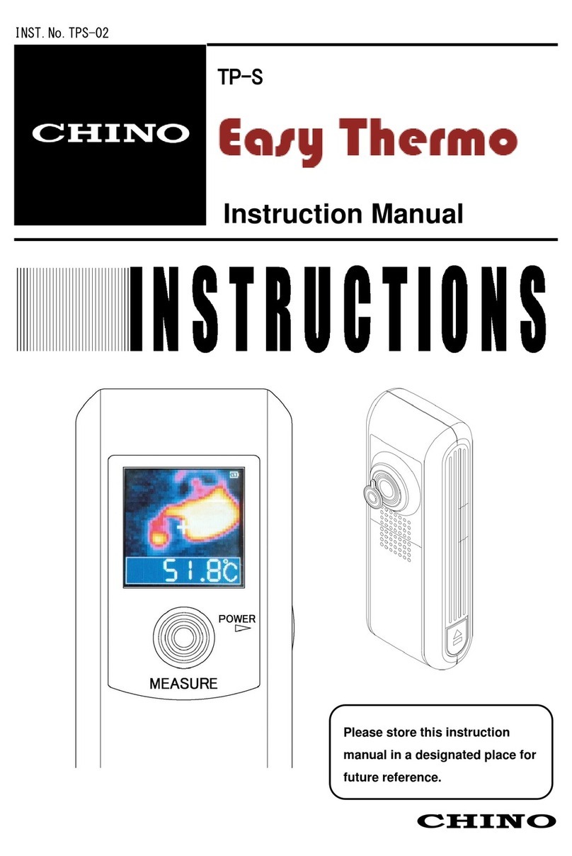
Chino TP-S Easy Thermo User manual

Chino
Chino IR-E Series User manual

Chino
Chino IR-H Series User manual

Chino
Chino IR-AH Series User manual

Chino
Chino IR-CAK User manual

Chino
Chino IR-BAT Series User manual

Chino
Chino IR-CA series User manual

Chino
Chino IR-BZ Series User manual