DRAKE ND-24-IP User manual

937-746-4556
www.rldrake.com
ND-24-IP
Network Decoder with HD-SDI, HDMI and Component Outputs
INSTRUCTION MANUAL
Model Item # Description
ND-24-IP 1002643 Network Decoder with SDI, HDMI and Component output
ND-RP-2 1002653 Rack Panel ND-24-IP
ND-24-Zixi-LIC 1002654 Zixi Link License Required for Point-to-Point Links
Rev: 042219 / 651246700D© 2019 R.L. Drake Holdings, LLC.

2800-523-6049 | www.rldrake.com
We recommend that you write the following information in the spaces provided below.
This product incorporates copyright protection technology that is protected by U.S. patents and other intellectual property
rights. Reverse engineering or disassembly is prohibited.
Purchase Location Name:
Purchase Location Telephone Number:
ND-24-IP Serial Number
Product Documentation:
Download the latest User Manual (PDF) by visiting our website. Navigate to the product page by entering the full
Model Name or Stock Number in the search field. Upon reaching the product page, the "User Manual" and other
downloads are made available beneath the product image.
Cross-Reference & Hyperlinking Usage:
This guide makes use of hyperlinks for the Table of Contents, some cross-reference linking between sections, and
external hyperlinking to web addresses. This has been done to assist the reader in finding the information they are
seeking in a much quicker way. In addition to hyperlinking, the Table of Contents also makes use of the bookmarking
feature present in the Adobe Reader application.
Firmware Updates:
For more information regarding the latest product firmware releases, please visit our website at www.rldrake.com. The
Firmware Updates page is available under the "Support" menu option within the main navigation. General instructions
for the FTP site, as well as updating your firmware, are provided on this page. For further assistance, you may also

3
800-523-6049 | www.rldrake.com
Table of Contents
GENERAL & SAFETY INSTRUCTIONS
IMPORTANT SAFETY INSTRUCTIONS......................................................................................................4
GENERAL DESCRIPTION & FEATURES .....................................................................................................6
SPECIFICATIONS.......................................................................................................................................7
FRONT AND REAR PANEL OPERATION ....................................................................................................8
INSTALLATION & SETUP
INSTALLATION & POWER-UP ...................................................................................................................9
FRONT-PANEL CONFIGURATION .............................................................................................................. 9
LOGIN SETUP ...........................................................................................................................................14
UNIT CONFIGURATION
PLAYER CONTROL....................................................................................................................................15
PLAYER CONTROL: UDP UNICAST................................................................................................................... 16
PLAYER CONTROL: UDP MULTICAST ..............................................................................................................17
PLAYER CONTROL: RTSP.................................................................................................................................. 18
PLAYER CONTROL: RTP WITH SDP ................................................................................................................. 19
PLAYER CONTROL: ZIXI PUSH ......................................................................................................................... 20
VIDEO SETTINGS......................................................................................................................................21
SYSTEM INFORMATION...........................................................................................................................22
SYSTEM LOG ............................................................................................................................................24
ADMINISTRATION PANEL
ADMIN PAGE.............................................................................................................................................25
FIRMWARE UPDATES
UPDATE.....................................................................................................................................................26
SERVICE & WARRANTY
SERVICE....................................................................................................................................................30
LIMITED WARRANTY................................................................................................................................31

4800-523-6049 | www.rldrake.com
Important Safety Instructions
1. Read Instrucons—All the safety and operang instrucons should be read before the
product is operated.
2. Retain Instrucons—The safety and operang instrucons should be retained for future
reference.
3. Heed Warnings—All warnings on the product and in the operang instrucons should be
adhered to.
4. Follow Instrucons—All operang and use instrucons should be followed.
5. Cleaning—Unplug this product from the wall outlet before cleaning. Do not use liquid
cleaners or aerosol cleansers. Use a damp cloth for cleaning.
6. Aachments—Do not use aachments that are not recommended by the product manu-
facturer as they may cause hazards.
7. Water and Moisture—Do not use this product near water—for example, near a bathtub,
wash bowl, kitchen sink or laundry tub; in a wet basement; or near a swimming pool; and
the like.
8. Accessories—Do not place this product on an unstable cart, stand, tripod, bracket, or
table. The product may fall, causing serious injury to a child or adult, and serious damage
to the product. Use only with a cart, stand, tripod, bracket, or table recommended by the
manufacturer, or sold with the product. Any mounng of the product should follow the
manufacturer’s instrucons, and should use a mounng accessory recommended by the
manufacturer.
9. A product and cart combinaon should be moved with care. Quick stops, excessive force,
and uneven surfaces may cause the product and cart combinaon to overturn.
10. Venlaon—Slots and openings in the cabinet are provided for venlaon and to ensure
reliable operaon of the product and to protect it from overheang, and these openings
must not be blocked or covered. The openings should never be blocked by placing the
product on a bed, sofa, rug, or similar surface. This product should not be placed in a built-in
installaon such as bookcase or rack unless proper venlaon is provided or the manufac-
turer’s instrucons have been adhered to.
11. Power Sources—This product should be operated only from the type of power source
indicated on the marking label. If you are not sure of the type of power supplied to your
home, consult your product dealer or local power company. For products intended to oper-
ate from baery power, or other sources, refer to the operang instrucons.
12. Grounding or Polarizaon—This product may be equipped with a polarized alternat-
ingcurrent line plug (a plug having one blade wider than the other). This plug will t into
the power outlet only one way. This is a safety feature. If you are unable to insert the plug
fully into the outlet, try reversing the plug. If the plug should sll fail to t, contact your
electrician to replace your obsolete outlet. Do not defeat the safety purpose of the polarized
plug. Alternate Warnings—If this product is equipped with a three-wire grounding-type
plug, a plug having a third (grounding) pin, the plug will only t into a grounding-type power
outlet. This is a safety feature. If you are unable to insert the plug into the outlet, contact
your electrician to replace your obsolete outlet. Do not defeat the safety purpose of the
grounding-type plug.
13. Power-Cord Protecon—Power-supply cords should be routed so that they are not
likely to be walked on or pinched by items placed upon or against them, paying parcular
aenon to cords at plugs, convenience receptacles, and the point where they exit from the
product.
14. Outdoor Antenna Grounding—If an outside antenna or cable system is connected to the
product, be sure the antenna or cable system is grounded so as to provide some protecon
against voltage surges and built-up stac charges. Arcle 810 of the Naonal Electrical Code,
ANSI/NFPA 70, provides informaon with regard to proper grounding of the mast and sup-
porng structure, grounding of the lead-in wire to an antenna discharge unit, size of ground-
ing conductors, locaon of antenna-discharge unit, connecon to grounding electrodes, and
requirements for the grounding electrode. See Figure A.
15. Lightning—For added protecon for this product during a lightning storm, or when it
is le unaended and unused for long periods of me, unplug it from the wall outlet and
disconnect the antenna or cable system. This will prevent damage to the product due to
lightning and power-line surges.
16. Power Lines—An outside antenna system should not be located in the vicinity of over-
head power lines, other electric light or power circuits, where it can fall into such power lines
or circuits.
17. Overloading—Do not overload wall outlets, extension cords, or integral convenience
receptacles as this can result in a risk of re or electric shock.
18. Object and Liquid Entry—Never push objects of any kind into this product through open-
ings as they may touch dangerous voltage points or short-out parts that could result in a re
or electric shock. Never spill liquid of any kind on the product.
19. Servicing—Do not aempt to service this product yourself as opening or removing cov-
ers may expose you to dangerous voltage or other hazards. Refer all servicing to qualied
service personnel.
20. Damage Requiring Service—Unplug this product from the wall outlet and refer servicing
to qualied service personnel under the following condions:
a. When the power-supply cord or plug is damaged,
b. If liquid has been spilled, or objects have fallen into the product,
c. If the product has been exposed to rain or water,
d. If the product does not operate normally by following the operang instrucons. Adjust
only those controls that are covered by the operang instrucons as an improper adjust-
ment of other controls may result in damage and will oen require extensive work by a
qualied technician to restore the product to its normal operaon,
e. If the product has been dropped or damaged in any way, and
f. When the product exhibits a disnct change in performance—this indicates a need for
service.
21. Replacement Parts—When replacement parts are required, be sure the service techni-
cian has used replacement parts specied by the manufacturer or have the same characteris-
cs as the original part. Unauthorized substutes may result in re, electric shock or other
hazards.
22. Safety Check—Upon compleon of any service or repairs to this product, ask the service
technician to perform safety checks to determine that the product is in proper operang
condion.
23. Wall or Ceiling Mounng—The product should be mounted to a wall or ceiling only as
recommended by the manufacturer.
24. Heat—The product should be situated away from heat sources such as radiators, heat
registers, stoves, or other products (including ampliers) that produce heat.
NOTE TO CATV SYSTEM INSTALLERS:
THIS REMINDER IS PROVIDED TO CALL THE CATV
SYSTEM INSTALLER’S ATTENTION TO ARTICLE 820 - 40
OF THE NEC WHICH PROVIDES GUIDELINES FOR PROPER
GROUNDING AND, IN PARTICULAR, SPECIFIES THAT
THE CABLE GROUND SHALL BE CONNECTED TO THE
GROUNDING SYSTEM OF THE BUILDING, AS CLOSE TO
THE POINT OF CABLE ENTRY AS PRACTICAL.
FIGURE A
Example of antenna grounding as per Naonal Electrical Code, ANSI/NFPA 70
ANTENNA
LEAD IN
WIRE
ANTENNA
DISCHARGE UNIT
(NEC SECTION 810-20)
GROUNDING
CONDUCTORS
(NEC SECTION 810-21)
POWER SERVICE GROUNDING ELECTRODE
SYSTEM (NEC ART 250, PART H)
ELECTRIC
SERVICE
EQUIPMENT
GROUND CLAMPS
GROUND CLAMP
NEC - NATIONAL ELECTRIC CODE
WARNING: TO PREVENT FIRE OR
ELECTRICAL SHOCK DO NOT
EXPOSE TO RAIN OR MOISTURE
RISK OF ELECTRIC SHOCK
DO NOT OPEN
WARNING: TO REDUCE THE RISK OF ELECTRIC SHOCK, DO NOT
REMOVE POWER SUPPLY COVERS
NO USER-SERVICEABLE PARTS INSIDE
REFER SERVICING TO QUALIFIED PERSONNEL
! CAUTION !
CAUTION STATEMENT
An appliance and cart combinaon should be moved with care. Quick stops, excessive
force and uneven surfaces may cause the appliance and cart combinaon to overturn.
The exclamaon point within an equilateral triangle is intended to alert the user to
the presence of important operang and maintenance (servicing) instrucons in the
literature accompanying the appliance.
The lightning ash with arrow head symbol, within an equilateral triangle, is intended to
alert the user to the presence of uninsulated “dangerous voltage” within the product’s
enclosure that may be of sucient magnitude to constute a risk of electric shock to
persons.
WARNING: TO REDUCE THE RISK OF FIRE OR ELECTRIC SHOCK, DO NOT EXPOSE THIS
APPLIANCE TO RAIN OR MOISTURE. DO NOT OPEN THE CABINET, REFER
SERVICING TO QUALIFIED PERSONNEL ONLY.
CAUTION: TO PREVENT ELECTRIC SHOCK, DO NOT USE THIS (POLARIZED) PLUG WITH AN
EXTENSION CORD RECEPTACLE OR OTHER OUTLET UNLESS THE BLADES CAN
BE FULLY INSERTED TO PREVENT BLADE EXPOSURE.
General & Safety Instructions

5
800-523-6049 | www.rldrake.com
Importantes De Sécurité
1. Lire les direcves—Toutes les direcves de sécurité et d’ulisaon devraient être lues
avant de mere l’appareil en opéraon.
2. Conserver les direcves—Les direcves de sécurité et d’ulisaon devraient être con-
servées pour consultaon future.
3. Tenir compte des averssements—Tous les averssements apparaissant sur l’appareil et
dans les consignes d’ulisaon devraient être respectés.
4. Suivre les direcves—Toutes les direcves d’opéraon et d’ulisaon devraient être
suivies.
5. Neoyage—Débrancher l’appareil de la prise électrique murale avant le neoyage. Ne pas
uliser de neoyants liquides ou aérosols. Employer un linge humide pour le neoyage.
6. Fixaon—Ne pas uliser d’autres xaons que celles recommandées par le manufacturier;
elles pourraient être source de dangers.
7. Eau et humidité—Ne pas uliser cet appareil près de l’eau. Par exemple, près d’une
baignoire, d’un bac de lavage, d’un évier de cuisine ou d’une cuvee de lessivage; dans un
sous-sol humide; ou à proximité d’une piscine; et autres environnements similaires.
8. Accessoires—Ne pas installer cet appareil sur un chariot, un socle, un trépied, un support
ou une table instables. L’appareil pourrait tomber, entraînant des blessures graves à un
enfant ou à un adulte, et des dommages importants à l’appareil. Employer seulement avec
un chariot, un socle, un trépied, un support, ou une table recommandés par le fabricant ou
vendu avec l’appareil. Toute installaon de l’appareil devrait être conforme aux direcves du
manufacturier et devrait uliser des accessoires d’installaon recommandés par celui-ci.
9. Un chariot supportant l’appareil devrait être déplacé avec précauon. Les arrêts brusques,
la force excessive et les surfaces inégales peuvent renverser le chariot.
10. Venlaon—Des fentes et ouvertures dans le châssis sont prévues pour la venlaon
de l’appareil, pour en assurer la abilité d’opéraon et le protéger contre la surchaue.
Ces ouvertures ne doivent pas être bloquées ou recouvertes. Ces ouvertures ne devraient
jamais être bloquées en plaçant l’appareil sur un lit, un sofa, une couverture, ou une surface
semblable. Cet appareil ne devrait pas être installé dans un meuble encastré comme une bib-
liothèque ou une étagère à moins de lui fournir une venlaon adéquate ou que l’installaon
soit conforme aux direcves du manufacturier.
11. Sources d’alimentaon électrique—Cet appareil devrait être ulisé seulement avec
le type d’alimentaon électrique inscrite sur l’équee. Si vous n’êtes pas certain du type
d’alimentaon électrique fourni à votre maison, consultez le vendeur de l’appareil ou
l’entreprises d’énergie locale. Pour des appareils alimentés par une baerie ou d’autres
sources, se référer aux consignes d’ulisaon.
12. Mise à la terre ou Polarisaon—Cet appareil est équipé avec un cordon d’alimentaon
à trois ls. Il est a brancher sur une prise ayant un connecteur a la terre. Assurez-vous que la
connecon a la terre ne manque pas.
13. Protecon du cordon d’alimentaon—Les cordons d’alimentaon devraient être dispo-
sés de façon à ce qu’on ne puisse marcher dessus ou qu’ils soient suscepbles d’être coincés
par des arcles placés sur ou contre eux. Une aenon parculière doit être portée aux
ches, prises de courant, et aux points où ils sortent de l’appareil.
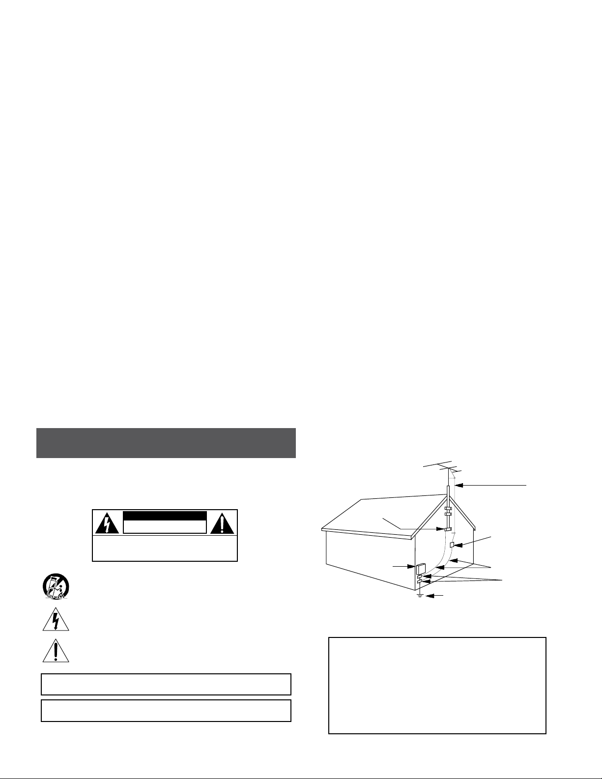
14. Mise à la terre de l’antenne extérieure—Si un système extérieur d’antenne ou de câble
est relié à l’appareil, s’assurer que le système d’antenne ou de câble est muni d’une mise à la
terre an de fournir une certaine protecon contre les surtensions et les charges d’électricité
staque. L’arcle 810 du code électrique naonal, ANSI/NFPA 70, fournit l’informaon néces-
saire en ce qui concerne la mise à la terre appropriée du mât et de la structure porteuse,
la mise à la terre du câble de connexion à une unité de décharge d’antenne, le calibre des
conducteurs de mise à la terre, la locaon de l’unité de décharge d’antenne, le raccordement
aux électrodes de mise à la terre et les spécicaons pour les électrodes de mise à la terre.
Voir la gure A.
15. Foudre—Pour une protecon supplémentaire de cet appareil pendant un orage élec-
trique, ou quand il est laissé sans surveillance et inulisé pendant de longues périodes, le
débrancher de la prise électrique murale et déconnecter le système d’antenne ou de câble.
Ceci préviendra les dommages à l’appareil dus à la foudre et aux surtensions.
16. Lignes électriques—Un système d’antenne extérieur ne devrait pas être situé à proximité
de lignes électriques aériennes ou de tout autre circuit électrique, où il pourrait tomber sur
de tels circuits ou lignes électriques. Lors de l’installaon d’un système d’antenne extérieur,
d’extrêmes précauons devraient être prises an de prévenir tout contact avec des lignes ou
circuits électriques. Entrer en contact avec de tels circuits ou lignes électriques pourrait être
fatal.
17. Surcharge—Ne pas surcharger les prises de courant murales, les rallonges électriques ou
les prises de courant intégrées. Un risque d’incendie ou de choc électrique pourrait résulter
d’une telle surcharge.
18. Inseron d’objet ou de liquide—Ne jamais insérer d’objet par les ouvertures de cet
appareil. Il pourrait toucher des points de voltage dangereux ou court-circuiter des pièces,
ce qui pourrait résulter en incendie ou en choc électrique. Ne jamais verser de liquide sur
l’appareil.
19. Entreen—Ne pas essayer de faire soi-même l’entreen de cet appareil. En ouvrir ou en
rerer les couvercles pourrait vous exposer à des voltages dangereux ou à d’autres dangers.
Coner tout entreen à un personnel de service qualié.
20. Dommage exigeant un entreen—Débrancher cet appareil de la prise de courant élec-
trique et coner l’entreen au personnel de service qualié dans les éventualités suivantes:
a. Quand le cordon d’alimentaon ou sa che sont endommagés,
b. Si des objets sont tombés dans l’appareil, ou si du liquide y a été renversé,
c. Si l’appareil a été exposé à la pluie ou à l’eau,
d. Si l’appareil ne fonconne pas normalement en suivant les consignes d’ulisaon.
Ajuster seulement les commandes qui sont menonnées dans le guide d’opéraon. Un
mauvais ajustement des autres commandes pourrait causer des dommages à l’appareil et
souvent exiger un travail supplémentaire de la part d’un technicien qualié pour remere
l’appareil en état normal d’opéraon.
e. Si l’appareil a été échappé ou endommagé de n’importe quelle façon, et
f. Quand l’appareil montre un changement notable de performance – ceci indique qu’un
entreen est nécessaire.
21. Pièces de rechange—Si des pièces de rechange sont nécessaires, s’assurer que le tech-
nicien de service a employé des pièces de rechange spéciques du manufacturier ou ayant
les mêmes caractérisques que les pièces originales. L’ulisaon de pièces de rechange non
autorisées pourrait résulter en incendie, choc électrique ou autres dangers.
22. Véricaon de sécurité—À la suite de toute réparaon ou entreen de cet appareil,
demander au technicien de service d’exécuter des véricaons de sécurité an de s’assurer
que l’appareil est en condion normale de fonconnement.
23. Montage au mur ou au plafond—L’appareil ne devrait être monté au mur ou au plafond
qu’uniquement de la façon recommandée par le manufacturier.
24. Chaleur—L’appareil devrait être situé loin de sources de chaleur telles que des radia-
teurs, des registres de chaleur, des fourneaux, ou d’autres appareils (y compris amplica-
teurs) produisant de la chaleur.
NOTE AUX INSTALLATEURS DE SYSTÈME DE CATV:
CE RAPPEL EST FOURNI POUR PORTER À L’ATTENTION DES
INSTALLATEURS DE SYSTÈME DE CATV, L’ARTICLE 820 - 40 DU
NEC QUI DONNE DES DIRECTIVES POUR UNE MISE À LA TERRE
APPROPRIÉE ET, EN PARTICULIER, SPÉCIFIE QUE LE CÂBLE DE
MISE À LA TERRE DEVRAIT ÊTRE RACCORDÉ AU SYSTÈME DE
MISE À LA TERRE DU BÂTIMENT LE PLUS PRÈS POSSIBLE DE
L’ENTRÉE DU CÂBLE.
FIGURE A
Exemple de mise à la terre d’antenne selon le Code Électrique Naonal, ANSI/NFPA 70
ANTENNA
LEAD IN
WIRE
UNITÉ DE DÉCHARCHE D’ANTENNE
(NEC SECTION 810-20)
CONDUCTEURS DE MISE À LA TERRE
(NEC SECTION 810-21)
SYSTÈME DE MISE À LA TERRE DU BÂTIMENT
(NEC ART 250, PART H)
APPAREILS
ÉLECTRIQUES
DE SERVICE
ATTACHES DE
MISE À LA TERRE
ATTACHES DE
MISE À LA TERRE
NEC - CODE ÉLECTRIQUE NATIONAL
AVERTISSEMENT: AFIN D’ÉVITER TOUT RISQUE D’INCENDIE
OU D’ÉLECTROCUTION, NE PAS EXPOSER CET APPAREIL À LA
PLUIE OU À L’HUMIDITÉ.
RISQUE DE CHOC ELECTRIQUE -
NE PAS OUVRIR
ATTENTION: POUR RÉDUIRE LE RISQUE D’ÉLECTROCUTION, NE PAS
ENLEVER LE DOS DE L’APPAREIL NI OUVRIR LE BOÎTIER. AUCUNE PIÈCE N’EST
RÉPARABLE PAR L’UTILISATEUR À L’INTÉRIEUR. SE RÉFÉRER UNIQUEMENT À
DES TECHNICIENS QUALIFIÉS POUR L’ENTRETIEN.
! AVERTISSEMENT !
Une combinaison de l’appareil et chariot doit être déplacé avec précauon. Des arrêts
brusques, une force excessive et des surfaces inégales peuvent causer la combinaison
de l’appareil et le chariot.
Le point d’exclamaon à l’intérieur d’un triangle équilatéral est desné à alerter
l’ulisateur sur la présence d’opéraons d’entreen importantes au sujet desquelles des
renseignements se trouvent dans le manuel d’instrucons.
Le symbole de l’éclair à l’intérieur d’un triangle équilatéral est desné à alerter
l’ulisateur sur la présence d’une “tension dangereuse” non isolée dans le boîer du
produit. cee tension est susante pour provoquer l’électrocuon de personnes.
ATTENTION DÉCLARATION
AVERTISSEMENT: AFIN D’ÉVITER TOUT RISQUE D’INCENDIE OU D’ÉLECTROCUTION, NE PAS
EXPOSER CET APPAREIL À LA PLUIE OU À L’HUMIDITÉ. NE PAS OUVRIR LE
BOÎTIER, CONFIER TOUS TRAVAUX À DU PERSONNEL TECHNIQUE QUALIFIÉ.
CAUTION: POUR PREVENIR LES CHOCS ELECTRIQUES, NE PAS UTILISER CETTE FICHE
POLARISEE AVEC UN PROLONGATEUR, UNE PRISE DE COURANT OU UNE
AUTRE SORTIE DE COURANT, SAUF SI LES LAMES PEUVENT ETRE INSEREES A
FOND SANS EN LAISSER AUCUNE PARTIE A DECOUVERT.

6800-523-6049 | www.rldrake.com
INTRODUCTION
The ND-24-IP is a low cost professional MPEG-2 and H.264 decoder that is capable of receiving content from off-air, clear
QAM, and IP sources. The ND-24-IP is capable of simultaneously outputting video content in SDI, HDMI and component
formats. SDI outputs are available in 3G-SDI, HD-SDI, or SD-SDI formats.
The unit can be used as a stand-alone high quality decoder, or used in conjunction with other IP encoders, to provide an
end-to-end IP video delivery solution over a managed network.
When the ND-24-IP decoder is used with Drake’s PEG encoder (with Zixi option) and a Zixi Link License, it can provide a
point-to-point reliable IP video transport from anywhere in the world with an internet connection. The ND-24-IP can also be
used in a point-to-multipoint application, where the ND-24-IP would decode the IP based Zixi protocol stream from a Zixi
Broadcaster.
General Description & Features
ND-RP-2 (stk # 1002653) - Rack Panel for two (2) ND-24-IP Decoders
FEATURES
• Simultaneous SDI/HDMI/Component HD + Composite SD Outputs
• Decoding content from O-Air, Clear QAM, and IP sources
• Supports both MPEG-2 and H.264 content
• LCD screen
• Closed Captioning
• VBR or CBR
• IGMPv2 and IGMPv3
• IP Security Camera Decoding (VLC Compatible)

7
800-523-6049 | www.rldrake.com
Specifications
Specicaons are subject to change without noce or obligaon.
INPUT
IP Mode
Connectors: RJ-45
Standard: 100/1000Base-T Ethernet
UDP/RTP: Supported
Protocols: IGMPv3/IGMPv2 Supported
Stream Porolio
SPTS and MPTS: Null Packet Deleon
Bit Rate: Variable and Constant
8VSB Mode
Connectors: 1x “F” Female
Standard: ATSC Digital Television A/53E
Tuning Range: UHF (Ch.14-69), VHF (Ch.2-13)
Data Rate: 19.392 MHz
Bandwidth: 6 MHz
Power Level: -20 to +20 dBmV
Impedance: 75 Ω
QAM Mode
Connectors: 1x “F” Female
Standard: ITU-T J.83; Annex A and B
(64 & 256 QAM)
Tuning Range: CATV Ch. 2-158 (STD, HRC, IRC)
Data Range: 38.8 Mbps (QAM 256);
26.97 Mbps (QAM 64) – Auto Detect
Bandwidth: 6 MHz
Power Level: -15 to 20 dBmV (@ QAM 256),
-20 to 20 dBmV (@ QAM 64)
Impedance: 75 Ω
OUTPUT
3G/HD/SD-SDI
Connectors: 1x BNC
Standards: SMPTE 424M (3G), SMPTE 292M (HD)
& SMPTE 259M (SD)
Video Resoluon: 480i, 720p, 1080i, & 1080p
Audio: Embedded PCM
HDMI
Connectors: 1x HDMI
Video Resoluon: 480i, 720p, 1080i, & 1080p
Audio: Embedded PCM
Composite
Connectors: 1x RCA for Video (Y)
Video Resoluon: 480i
Audio: 2x RCA for Analog Audio (L,R)
Component
Connectors: 3x RCA for Video (Y, Pb, Pr)
Video Resoluon: 480i, 720p, & 1080i
Video Aspect Rao: 4:3 & 16:9
Audio: 2x RCA for Analog Audio (L,R)
Digital Audio (SPDIF)
Connectors: 1x RCA
ALARMS/MONITORING/CONTROL
Local
Monitoring: Front-panel LCD screen
Control: Front-panel Navigaonal Key-pad
Remote
Monitoring/
Control: GUI-based menu via Web browser
(1x RJ45 rear-panel connector; 100/1000Base-T)
GENERAL
Mechanical
Dimensions: 8.69 x 8.0 x 1.97 inches
(220.7 x 203 x 50.0 mm)
Unit Weight: 1.87 lbs (0.85 kg)
Unit & Power
Transformer Weight: 2.18 lbs (0.99 kg)
Shipping Weight: 2.6 lbs (1.18 kg)
Operang Temperature: 32 to 122 °F (0 to 50 °C)
Storage Temperature: -13 to 158 °F (-25 to 70 °C)
Operang Humidity: 0 to 95% RH @ 35 °C max,
non-condensing
Storage Humidity: 0 to 95% RH @ 35 °C max,
non-condensing
Power
Power: 100-240 VAC 50/60 Hz / 5 VDC @
2.5 A; External Power Supply
Power Consumpon: 10 W
ND-24-IP • Item # 1002643
Network Decoder with HD-SDI, HDMI and Component Outputs

8800-523-6049 | www.rldrake.com
FRONT PANEL
LCD Display: used for Network Settings (as shown under “Front-Panel Conguration”)
Controls: used for Network Settings (as shown under “Front-Panel Conguration”)
REAR PANEL
HDMI Out: HDMI A/V Output
HD-SDI Out: HD/SD SDI Output *(1)
SPDIF: S/PDIF Digital Audio Output
Audio Out: Analog L+R Audio Output
Video Out: Composite Analog Video Output *(1)
Component Out: Component Video Output
Remote Control: GigE Ethernet Port for User Interface
Data Input: GigE Ethernet Port for IP Input
Expansion Port (not used)
8VSB/QAM Input: Digital Tuner Input
+5VDC, 2.0A: DC supplied from included AC adapter.
Front and Rear Panel Operation
1
2
3
4
8
5
9
6
10
12
7
11
13
3
*(1) Note - Current rmware allows for SD-SDI or composite video. When the video resolution is 480i and SD-SDI is set to
"Enable", you'll get SD-SDI, but NOT composite. If SD-SDI is set to "Disable", you'll get composite, but not SD-SDI. If the
video resolution is anything other than 480i, this has no effect.
1
6 7 9
2
4 5 8 10 11 12
13

9
800-523-6049 | www.rldrake.com
Installation & Power-Up
Front-Panel Configuration
Unpacking
You will nd the following items in the box:
• ND-24-IP Network Decoder (QTY = 1)
• ND-24-IP Quick Guide
• ND-24-IP AC Adapter (QTY = 1)
Installation
The ND-24-IP is designed to be mounted in the close proximity to a 120 VAC – 60 Hz power plug.
For safe and reliable operation, do not block airflow.
In addition to the described functions of the keys above, there are additional functions which they serve while conguring or
going through the menu on the LCD display.
Menu Items: the LEFT ARROW key acts as “Back” button, returning to the previous level in the hierarchy.
Read-Only Items: the LEFT ARROW key acts as “Back” button, returning to the previous menu level.
Editable Items: the LEFT and RIGHT ARROW keys will move the cursor left and right, the UP and DOWN ARROW
keys will modify the value at the cursor, and the ENTER key will accept the new value and return to the previous menu.
Display Menu Navigation
KEY NAME FUNCTION
UP / DOWN
ARROWS
Moves the item selecon cursor, indicated on-screen by a right-arrow symbol, up and
down between menu items on the LCD display.
LEFT / RIGHT
ARROWS
Moves the item selecon cursor, indicated on-screen by a right-arrow symbol, le and
right through menu items on the LCD display.
ENTER Enters the selected menu item, which can be a sub-menu, a read-only status (e.g.
“Display MAC”), or an editable parameter (e.g. “Edit Address”).
Installation & Setup
Power-Up
Plug the AC Adapter into the back of the ND-24-IP unit at the input marked “+5VDC, 2.0A” and then into an AC power plug
(120 VAC – 60 HZ).

10 800-523-6049 | www.rldrake.com
Front-Panel Configuration
IMPORTANT: The Control Port (Management Port) and the Data Port
MUST be on different subnets.
Network Sengs
|
|-- Control (eth1)
| |
| |- Edit Cfg (eth1)*
| | |- Enable DHCP
| | |- Edit Address**
| | |- Edit Netmask**
| | |- Edit Gateway**
| |
| |- Display IP
| |- Display MAC
| |- Display Netmask
|
|-- Data (eth0)
| |
| |- Edit Data (eth0)*
| | |- Enable DHCP
| | |- Edit Address**
| | |- Edit Netmask**
| | |- Edit Gateway**
| |
| |- Display IP
| |- Display MAC
| |- Display Netmask
The ND-24-IP has two-rear panel network ports, labeled Remote Control and Data Input, nd are only congurable through
the LCD. To begin network conguration, press ENTER on the front panel and select “Network Settings”.
Configuring the Network
* Changes will not be applied until backing out of the “Edit XXX (ethX)” menu
for an interface, at which point you will be prompted to conrm changes.
Selecting "No" at the prompt will retain existing settings for that interface.
** Edit Address/Netmask/Gateway options will not be displayed if DHCP is
enabled on the interface.
The following options will appear:
> Control (eth1)
> Data (eth0)
Select the port you wish to congure using the up and down arrows.
> Edit Network Cfg (eth#)
(where “#” species the port.)
Display Menu Hierarchy
The LCD Menu is accessed through the front panel. The directional arrows both navigate through the menus as well as allow
input of specic parameter settings. The following hierarchy is sectioned by Main Menu options:
ND-24 -IP STATUS
The ND-24-IP Status display menu and sub-menus allow the user to view the current settings without logging into the unit
through the web.
N D-2 4-IP St at us
Tuner Locked, Chan. Broadcast xx, SNR xx, Constell (QAM/8VSB)
Multicast Multicast Port xxx, IP Addr xxx.xxx.xxx.xxx
Unicast Port xxxx
RTSP (URL Setting), input stream, rtsp://root:pass@xxx.xxx.xxx.xxx, media/webpage
SDP
RTP with SDP Mode ABCD xxxxxxxx
Front-Panel LCD Menu - “ND-24-IP Status”
NETWORK SETTINGS
The Network Settings display menu and sub-menus provide a method for the user to set up the Data and Control ports. The
user can then access the unit from the web control panel to continue setup of the unit. See the “Conguring the Network"
section for more information on conguring the unit's network settings.

11
800-523-6049 | www.rldrake.com
Front-Panel Configuration
VIDEO SETTINGS
The Video Settings display menus provide a method for the user to select the Video Format and Enable/Disable the SD/SDI.
Network Settings
Control (eth1)
Edit Network Cfg
Enable DHCP Enable DHCP
YES NO
Edit Address Set Address
172.016.130.033
Edit Netmask Set Netmask
255.255.255.000
Edit Gateway Set Gateway
172.016.130.254
Display IP IP Address (eth1)
172.16.130.33
Display MAC MAC Address (eth1)
0:14:39:0:99:4E
Display Netmask Netmask (eth1)
255.255.255.0
Data (et h0)
Edit Network Cfg
Enable DHCP Enable DHCP
YES NO
Edit Address Set Address
172.076.255.118
Edit Netmask Set Netmask
255.255.255.000
Edit Gateway Set Gateway
172.076.255.254
Display IP IP Address (eth0)
72.76.255.118
Display MAC MAC Address (eth0)
0:14:39:0:99:4D
Display Netmask Netmask (eth1)
255.255.255.0
Front-Panel LCD Menu - “Network Settings”
Video Settings
*Enable SDSDI Enable SD/SDI
YES NO
*Select Video Format
Auto
1080p60
1080p59.94
1080p30
1080p29.97
1080i60
1080i59.94
720p60
720 p59.94
480i60
480i59.94
Front-Panel LCD Menu - “Video Settings”
SOURCE SETTINGS
The Source Settings display menu and sub-menus provide a method for the user to set up the Channel Plan, Channel
Number and Modulation settings. The user is able to set up the source further through the web control panel.
NETWORK SETTINGS (CONTINUED)

12 800-523-6049 | www.rldrake.com
Front-Panel Configuration
SOURCE SETTINGS (CONTINUED)
Source Settings
Display Source Type Source Type
Tuner
Tuner Cfg
Edit Tuner Cfg
*Change Channel Set Chan
2
*Select Channel Plan STD, IRC, HRC
Broadcast
*Select Modulation QAM
8VSB
Display Lock Status Tuner Lock Status
Locked
Display Power Tuner Power Status
-41.0 dB
Display Symbol Rate Tuner Symbol Rate
5.360000
Display BERPER Tuner BER PER
0.000000
Display Mode Tuner Mode
QAM
Display SNR Tuner SNR
39
Display Constellati Tuner Constellation
QAM256
Display Channel Tuner Channel
2
Display Plan Tuner Plan
STD
Unicast Cfg
Edit Unicast Cfg *Edit Port Set Unicast Port
50000
Display Port Unicast Port
50000
Multicast Cfg
Edit Multicast Cfg
*Edit Multicast Grou Set Multicast Group
239.010.010.010
*Edit Port Set Multicast Port
50000
*Select IGMP IGMPv2
IGMPv3
Display Port Multicast Port
50000
Display MCast Group Multicast Group
239.10.10.10
Display IGMP IGMP Version
IGMPv2
Display Source 1 Multicast Source 1
172.xx.xx.xx
Display Source 2 Multicast Source 1
172.xx.xx.xx
RTSP Cfg Display URL URL
“Text”
RTPSDP Cfg Display SDP Text “Text”
Front-Panel LCD Menu - “Source Settings”

13
800-523-6049 | www.rldrake.com
Front-Panel Configuration
Source Settings
(Zixi - Optional)
Zixi Push Cfg
Display Port Zixi Push Port
2088
Display Stream ID Zixi Push Stream ID
decoder
Zixi Pull Cfg
Display Port Zixi Pull Port
2089
Display Stream ID Zixi Pull Stream ID
decoder
Display Remote ID Zixi Remote ID
decoder
Display Hostname Zixi Hostname
172.xx.xx.xx
Front-Panel LCD Menu - “Source Settings” (Zixi - Optional)
System Settings Reset Password
Factory Default All
Front-Panel LCD Menu - “System Settings”
SYSTEM SETTINGS
RESET PASSWORD: Resets the decoder to the default password of “pass” and the default username as "admin”.
Both password and username are case-sensitive.
FACTORY DEFAULT ALL: When selected the unit will revert back to the default settings of:
Username = admin (case-sensitive)
Password = pass (case-sensitive)
IP address = 172.16.80.1
SOURCE SETTINGS - ZIXI (OPTIONAL)
The sengs for Zixi (oponal) source are read-only through the LCD display menu. To set the push port or pull port shown
on the display menu, see the “Player Control" secon in this manual under “Zixi Push”.

14 800-523-6049 | www.rldrake.com
Login Setup
To begin setup, connect the appropriate input and output video cables and plug in the ND-24-IP power cable.
ETHERNET ACCESS:
Local or remote communication with the unit is only possible through a GUI-based menu via any standard web browser.
Chrome or Firefox is recommended and for IE, use IE11 minimum. Before you can communicate with the unit you must
congure your computer's IP address to be on the same subnet as the ND-24-IP's Control IP address. To do so, follow these
steps:
Connect an Ethernet cable from your computer to the Control GigE port on the rear panel of the ND-24-IP.
The following steps explain how to do this for a computer with Windows 7 (or higher) operating software:
a) On your computer, navigate to the “Network and Sharing Center”.
(Note: Can be found using the search box in the Start Menu or for Windows 8+, the Start Screen)
b) Once open, click on “Change Adapter Settings” on left hand side of the window.
c) Right-click on the “Local Area Connection”, and then click on the “Properties”.
d) A dialog box entitled “Local Area Connection Properties” will appear. In this box, double-click on the
“Internet Protocol Version 4 (TCP/IPv4)”.
e) A dialog box entitled “Internet Protocol Version 4 (TCP/IPv4) Properties” will appear. Select the “Use the
following IP address” option and enter the following addresses:
IP address: same subnet as Control IP (eg.172.16.80.xxx where xxx is a different value than the one used for ND-24-IP)
Subnet mask: 255.255.255.0
No need to enter a value for the Default Gateway for local access.
Click OK to close the dialog box. Now your computer is ready to communicate with the unit.
Open a web browser on your computer and enter the URL
address (Control IP Address). Once the ND-24-IP web
page has been loaded, you will see a login dialog popup.
Enter the username and password and click LOGIN. The
factory default username is “admin” (all lower case) and
password is "pass" (all lower case).
NOTE: If you have any issues connecting, we recommend clearing the cache in the browser’s settings.
Webpage Timeout - User will be automatically logged out after 30 minutes of inactivity on webpages.

15
800-523-6049 | www.rldrake.com
Player Control
The "Player Control" congurable settings are determined by the selected "Source Type" (Figure 1) .
Figure 1 - "Player Control" - Source Type selections
Source Type:Tuner
Channel:RF channel to receive. Channels are dependent on "Channel Plan" ( ). Use up-down buttons or direct
channel entry for desired channel.
Channel Plan:CATV (STD,IRC,HRC) channel range 2 to 158. Broadcast channel range 2 to 69.
Modulation:Select QAM for CATV or 8VSB for Broadcast channel plans.
1
1
2
3
3
4
PLAYER CONTROL: INPUT
Figure 2 - "Player Control" - Tuner
2 3 4
5
6
7 8
1
1
Source Type: As shown above, source type options available are Tuner, UDP Unicast, UDP Multicast, RTSP, RTP with
SDP, Zixi Push, and Zixi Pull. The following sections explain conguring the source types in more detail.
Unit Configuration

16 800-523-6049 | www.rldrake.com
Revert Changes: Returns to previous settings after the last “Apply”.
Apply: Enters the current displayed settings into the decoder.
Source Type: UDP Unicast
UDP Port: Enter in port number to be used.
Program Selection:
Auto - Selects the rst program in the PAT table
Program Number - User enters the desired program number to receive.
Manual Select - When selected “Start Scan” button ( ) will be displayed.
Clicking on the “Start Scan” button will display all available programs. Select the desired program by checking the
respective Select box.
Player Control
1
2
5
3
6
5
6
7
8
Program Selection:
Auto - Selects the rst program in the PAT table
Program Number - User enters the desired program number to receive.
Manual Select - When selected “Start Scan” button ( ) will be displayed.
Start Scan: Available only when in Manual Select Program mode. Clicking on the scan button will display all available
programs. Select the desired program by checking the respective Select box.
Revert Changes: Returns to previous settings after the last “Apply”.
Apply: Enters the current displayed settings into the decoder.
PLAYER CONTROL: UDP UNICAST
Figure 3a - "Player Control" - UDP Unicast
3
5 6
1
2
Figure 3b - "Program Selection" - Start Scan
4
4
6

17
800-523-6049 | www.rldrake.com
Revert Changes: Returns to previous settings after the last “Apply”.
Apply: Enters the current displayed settings into the decoder.
Player Control
Source Type:UDP Multicast
Multicast Group:Enter IP address
Port:Enter in port number to be used.
IGMP Version:Supports either IGMPv2 or IGMPv3
Program Selection:
Auto - Selects the rst program in the PAT table
Program Number - User enters the desired program number to receive.
Manual Select - When selected "Start Scan" button ( ) will be displayed.
Clicking on the "Start Scan" button will display all available programs. Select the desired program by checking the
respective Select box.
PLAYER CONTROL: UDP MULTICAST
1
2
3
4
7
5
8
6
Figure 4a - "Player Control" - UDP Multicast
2 3 4
5
7 8
1
Figure 4b - "Program Selection" - Start Scan
6

18 800-523-6049 | www.rldrake.com
Player Control
PLAYER CONTROL: RTSP
Source Type: RTSP
URL: Enter URL address in RTSP protocol format.
Formatting of the URL: rtsp://user:pass:@<ipaddress>/camera info
“rtsp” - The type of protocol to enable streaming of the IP output of camera.
“user:pass” - The login and password information for the camera (refer to camera manual).
“<ipaddress>/” - Insert the IP address of the camera.
“Camera info” - This is related to each camera (refer to camera manual).
Program Selection:
Auto - Selects the rst program in the PAT table
Program Number - User enters the desired program number to receive.
Manual Select - When selected “Start Scan” button ( ) will be displayed.
Clicking on the “Start Scan” button will display all available programs. Select the desired program by checking the
respective Select box.
4
Figure 5b - “Program Selection” - Start Scan
4
1
2
3
5
6
Figure 5a - “Player Control” - RTSP
2
3
5 6
1
Revert Changes: Returns to previous settings after the last “Apply”.
Apply: Enters the current displayed settings into the decoder.

19
800-523-6049 | www.rldrake.com
Revert Changes: Returns to previous settings after the last “Apply”.
Apply: Enters the current displayed settings into the decoder.
Player Control
Source Type: RTP with SDP
SDP Text: SDP (Session Description Protocol) prole text here in order to use with RTP (Real-time Transport Protocol)
Source Type.
Program Selection:
Auto - Selects the rst program in the PAT table
Program Number - User enters the desired program number to receive.
Manual Select - When selected “Start Scan” button ( ) will be displayed.
Clicking on the “Start Scan” button will display all available programs. Select the desired program by checking the
respective Select box.
PLAYER CONTROL: RTP WITH SDP
1
2
5
3
6
Figure 6b - "Program Selection" - Start Scan
4
4
Figure 6a - "Player Control" - RTP with SDP
2
3
1
5 6

20 800-523-6049 | www.rldrake.com
Source Type: Zixi Push will display in drop down menu only after the License Key has been entered.
Zixi Port: specify Zixi Port
Channel/Stream ID: must match either a PEG encoder ID for point-to-point or Zixi server stream ID for broadcast
applications
Password: must match either a PEG encoder password for point-to-point or Zixi server stream password for broadcast
applications
Program Selection:
Auto - Selects the rst program in the PAT table
Program Number - User enters the desired program number to receive.
Manual Select - When selected “Start Scan” button ( ) will be displayed.
Start Scan: Available only when in Manual Select Program mode. Clicking on the scan button will display all available
programs. Select the desired program by checking the respective Select box.
Revert Changes: Returns to previous settings after the last “Apply”.
Apply: Enters the current displayed settings into the decoder.
Player Control
PLAYER CONTROL: ZIXI PUSH
1
2
5
3
6
4
7
8
Figure 7 - "Player Control" - Zixi Push Input
2 3 4
5
6
7 8
1
If a Zixi Link License is not pre-installed with the unit for point-to-point links over the public internet, a separate Zixi Link
License (Model: ND-24-Zixi-LIC; P/N: 1002654) will be required.
6
Other manuals for ND-24-IP
2
This manual suits for next models
2
Table of contents
Other DRAKE Media Converter manuals

DRAKE
DRAKE 1002613A User manual

DRAKE
DRAKE DSE 2 PLUS User manual

DRAKE
DRAKE DSE24A User manual

DRAKE
DRAKE 1002613B User manual

DRAKE
DRAKE ND-24-IP User manual

DRAKE
DRAKE ENCODER HOST EH244 User manual

DRAKE
DRAKE TUM714 T User manual

DRAKE
DRAKE ND-24-IP User manual

DRAKE
DRAKE SDI24A User manual

DRAKE
DRAKE 1002606 User manual

DRAKE
DRAKE PEG PLUS User manual

DRAKE
DRAKE ENCODER HOST EH244 User manual

DRAKE
DRAKE DDC864 User manual

DRAKE
DRAKE DSE24A User manual

DRAKE
DRAKE SDM1000 User manual

DRAKE
DRAKE PEG-NE24-IP-C User manual

DRAKE
DRAKE PEG-NE24-IP User manual

DRAKE
DRAKE MMTS20 User manual

DRAKE
DRAKE HDE24 User manual

DRAKE
DRAKE HDE24 User manual