Drawell DW-TY-9900 User manual

1
COMPANY NAME
DW-TY-9900 Inductively Coupled Plasma Atomic Emission
Spectrometer
Operation manual
DRAWELL INTERNATIONAL TECHNOLOGY LIMITED
Chongqing Center : Suite 2605,Building No.11,Shiyou Road No.1, Yuzhong District, Chongqing, China.
Tel: 0086-023-63268643
Shanghai Office : Suite 1101,Lane561 XiuChuan Rd.,PuDong New Area,Shanghai,China
Tel: 0086-021-50966080
Homepage : www.drawell.com.cn

1
Chapter 1 DW-TY-9900 Inductively Coupled Plasma Atomic Emission Spectrometer (ICP-AES)
Overview...........................................................................................................................................1
1.1 The Main Structure of ICP-AES...................................................................................................1
1.2 Brief Description of the Main Working Principle of ICP-AES......................................................1
1.3 Application.................................................................................................................................1
1.4 Instrument Composition and Working Principle........................................................................1
1.5 The Main Features.....................................................................................................................2
1.6 The Main Specifications............................................................................................................2
Chapter 2 Working Environment and Facility Requirements............................................................3
2.1 Working Environment.................................................................................................................3
2.1.1 Room........................................................................................................................................3
2.1.2 Suitable Operating Environment..............................................................................................3
2.1.3 Good Dust Prevention Measures.............................................................................................3
2.2 Power Supply and Auxiliary Material Configuration...................................................................4
2.2.1 Stable Power Supply System....................................................................................................4
2.2.2 Power Requirements................................................................................................................4
2.2.3 Grounding Requirements.........................................................................................................5
2.2.4 Gas Requirements....................................................................................................................5
2.2.5 Cooling Water Requirements...................................................................................................5
2.2.6 Exhaust Requirements.............................................................................................................5
2.3 Other Requirements for Laboratory...........................................................................................5
Chapter 3 Installation.......................................................................................................................6
3.1 Unboxing.....................................................................................................................................6
3.2 Installation..................................................................................................................................6
3.3 Acceptance.................................................................................................................................9
3.4 The Packing List.........................................................................................................................10
Chapter 4 Operation.......................................................................................................................12
4.1 Instrument Operation...............................................................................................................12
4.1.1 Boot Operation DW-TY-9900 ICP Follow the Steps Below.....................................................12
4.2 Software Function and Operation Interface.............................................................................13
Chapter 5 Daily Maintenance and Precautions.............................................................................27
5.1 Daily Maintenance...................................................................................................................27
5.2 Precautions for Turn On/ Off....................................................................................................28
5.3 Precautions for Daily Maintenance..........................................................................................29
Chapter 6 Common Fault Diagnosis Analysis and Elimination.......................................................30

2
Chapter 1 DW-TY-9900 Inductively Coupled Plasma Atomic Emission
Spectrometer (ICP-AES) Overview
1.1 The Main Structure of ICP-AES
DW-TY-9900 Inductively Coupled Plasma Atomic Emission Spectrometer(ICP-AES) consists of
sampling system, spark source, dispersion system, control and detection system, and output
system.
1.2 Brief Description of the Main Working Principle of ICP-AES
ICP-AES is based on the characteristic radiation generated by the atoms or ions of the measured
element being excited in the light source. By judging the existence and intensity of this
characteristic radiation, qualitative and quantitative analysis of each element is carried out.
1.3 Application
As a large precision inorganic analytical instrument, DW-TY-9900 ICP Spectrometer is widely used
in
1. Steel and its alloys include carbon steel, cast iron, alloy steel, high purity steel, ferroalloy, etc.
2. Non-ferrous metals and their alloys include non-ferrous metals and their alloys, rare metals
and their alloys, precious metals, rare earth elements and their compounds.
3. Water quality samples such as drinking water, surface water, waste water, mineral water,
electroplating waste water.
4. Environmental samples include soil atmospheric dust, fly ash.
5. Mineral samples such as geological samples, ores and minerals.
6. Inorganic non-metallic materials.
7. Chemical products include chemical reagents, inorganic materials, cosmetics, oil(gasoline,
diesel, lubricating oil, C5 and other synthetic gasoline raw materials, oleic acid) petroleum
catalysts, urea solutions.
8. Food and drink.
9. Animal, plant and biochemical samples such as plants, Chinese medicine and animal tissues,
biochemical samples.
10. Nuclear industry products such as fuel, nuclear.
1.4 Instrument Composition and Working Principle
ICP inductively coupled plasma single-channel scanning spectrometer, is a multi-element analysis
of the sequence test measuring equipment. The instrument consists of scanning spectrometer,
radio frequency generator, the sample introduction system, photoelectric conversion, control
systems, data processing systems, and analysis software. Plasma is generated from the triple
concentric quartz tube in a torch. Argon is put into torch pipe in tangent direction, the upper part
of torch is coiled with copper loop(intercom cooling water). High-frequency generator generates
the high frequency current(40 MHz frequency around 1 KW power) through the coil, producing
around Alternating magnetic field, ionizing to produce a small amount of argon ion and electron,
in the magnetic field under the accelerated collisions with other neutral atoms, producing more
electronic and ions, in the form of eddy current, EDM reacts in the plasma formed under the
plasma torch( That is, plasma). The plasma temperature could be up to 10000 K or higher.
Aqueous solution measured by the formation of aerosol spray into the center of the quartz torch

3
channel. Atomic is ionized by energy of outsiders, but the atoms are in unstable state, and from
the high-level transition to the ground state, atoms will release tremendous energy, this energy is
a certain wavelength of electromagnetic radiation and is sent out. Different elements have
different spectral characteristics. These feature spectrum shoots grating of spectrometer through
the lens, computer rotates grating by controlling the stepper motor, transmission mechanism
posit elements characteristic spectra accurately to the slit, and photomultiplier change the
spectrum of light intensity to the current, then deal with the circuit and V/F conversion by
computer data processing, the final analysis is made by the printer.
1.5 The Main Features
1. High-quality optical components are equipped with an advanced control system, which
ensures accurate scanning and positioning to obtain test result signals with high signal-to-noise
ratio.
2. Imported products are used for key components to ensure the accuracy and sensitivity of the
instrument.
3. Small matrix effect: 99% of the samples do not need to separate the matrix.
4. Wide measurement range: analysis from ultra-micro to constant.
5. Stability: RSD≤1.5%.
6. Fast processing speed, sequential scanning of elements per minute up to 20 or more.
7. It can perform quantitative or qualitative analysis of 70 metal elements and some non-metal
elements.
8. High stability: RSD≤2.0%
9. The detection limit is very low: reach the national A-level standard.
10. It can do qualitative or quantitative analysis.
11. Convenient analysis software: the third-generation Chinese or English operating software
based on Windows XP, Windows7, Windows8, and Windows10 platforms, it makes the operation
easier, the software can be used directly without installation.
1.6 The Main Specifications
1. Scan wavelength range:3600r/nm 180-530nm
2400r/nm 180-800nm
2. Wavelength indication error: ≤±0.03nm, Repeatability≤0.003nm
3. Minimum spectral bandwidth: Mn 257.610nm, better than the national A-level
standard≤0.015
4. The detection limit(mg/L):Zn213.856nm≤0.003, Mn257.610nm≤0.002, Ba455.403nm≤0.001
Ni231.604nm≤0.01, Cr267.716nm≤0.007, Cu324.754≤0.007
Stability:RSD≤2.0%

4
Chapter 2 Working Environment and Facility Requirements
2.1 Working Environment
2.1.1 Room
The effective space of the room is about 12-15 square meters, which is suitable for keeping the
temperature. There are reagent cabinets with standard liquid, reagent racks, computer tables and
chairs, etc., and 1-2 air conditioners are installed.
2.1.2 Suitable Operating Environment
Ambient temperature:25℃±3℃(Temperature change rate within 2℃/h).
Relative humidity:70% or less(dehumidifiers should be installed in areas with high environmental
humidity).
Exhaust requirements: Doors and windows are tightly sealed to prevent sand and moisture from
entering.
Other requirements:The room is clean, dry, free of dust, no corrosive gas, and no vibration on
the ground.
Well grounded:resistance≤4Ω.
Plasma spectroscopy is a large-scale precision optical instrument that needs to operate in a
certain environment. Losing these conditions will not only make the instrument use poorly, but
also the instrument’s detection performance will not be fully utilized, even causing damage and
shortening its life. According to the characteristics of optical instruments, there are certain
requirements for ambient temperature and humidity. If the temperature change is too large, the
optical element will be affected by the temperature change will produce spectral line drift,
resulting in unstable measurement data, generally, the room temperature is required to be
maintained at a fixed temperature between 25±3℃, and the temperature change should be less
than ±1℃/h. If the ambient humidity is too high, optical components, especially gratings, optical
mirrors or lenses are easily damaged by moisture or have reduced performance. Electronic
systems, especially the components on printed circuit boards and high-voltage power supplies,
are easily damaged by moisture. The influence of humidity on the high-frequency generator is
also very important. Excessive humidity will cause the plasma to be difficult to ignite, or cause
high-voltage power supply and high-voltage circuit discharge to destroy components. Generally,
the indoor humidity should be less than 70%, and it is best to control it between 45-60%. If
necessary, an air purification device should be provided.
2.1.3 Good Dust Prevention Measures
Exhaust fans need to be installed in laboratories with spectrometers, when the exhaust fan is
working, there is a pressure difference between the laboratory and the outside, a negative
pressure is generated inside the laboratory, and the outdoor air containing a lot of dust flows into
the room through the gaps between doors and windows. A large amount of it accumulates on
various parts of the instrument, and it is easy to cause high-voltage components or connectors to
ignite, circuit boards, wiring, sockets, etc., short circuits, leakage, and various faults. Therefore,
frequent dust removal is required.
Especially computers, electronic control circuits, high-frequency generators, etc., are regularly

5
disassembled or opened, cleaned with a small brush, and at the same time, use a vacuum cleaner
to absorb the dust in each part. For the negative high-voltage power cord of the photomultiplier
tube, the high-voltage cords and connectors of the computer monitor, use gauze moistened with
a little absolute alcohol to carefully wipe off the carbon and dust.
For the dust removal of the instrument, the help of electronic instrument repair professionals. If
the user or manager of the instrument does not understand the structure of the instrument, do
not move it easily to avoid accidents. The dust removal should be carried out before stopping and
turning off the power supply.
2.2 Power Supply and Auxiliary Material Configuration
2.2.1 Stable Power Supply System
In order to ensure the safe operation of the ICP-AES, the power supply line must have a large
enough capacity, otherwise the voltage drop of the line during the operation of the instrument is
too large, which will affect the life of the instrument. As a precision measuring instrument, it also
needs a relatively stable power supply, and the change in power supply voltage generally does
not exceed ±1%, If it exceeds this range, you need to use a precision purified AC power supply, as
the general voltage stabilizer generates clipping when the voltage is high, it causes electric pulses,
which affects the work of electronic computers, microprocessors and phase sensitive amplifiers,
and causes malfunctions. The continuous sine wave power supply can ensure the normal
operation of these electronic circuits. The power supply circuit of the instrument should be
obtained separately from the distribution board of the power supply transformer. Try not to
share a power supply line with large motors, large ventilators, air conditioners, muffle furnaces
and other large electrical equipment. In order to avoid large fluctuations in the voltage of the
power supply line when these electrical equipment are started, resulting in unstable operation of
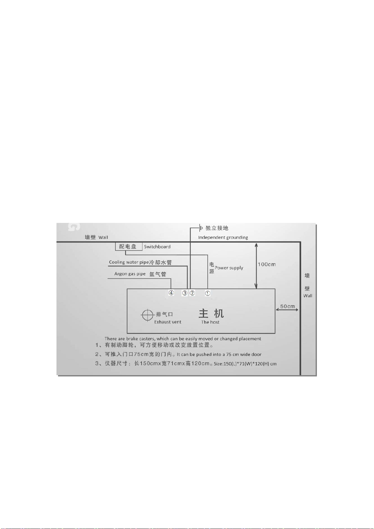
the instrument. Generally, the ground wire resistance of the spectrometer should be less than 4Ω,
and the computer ground wire resistance should be less than 0.25Ω(ASTM) to prevent mutual
interference.
In the operation of the instrument, the operator should always pay attention to the change of the
power supply voltage, and you cannot work under over-voltage or under-voltage for a long time.
When the instrument works under over-voltage, the life of the tube will be greatly
shortened(below 20% of the normal life). If working under the condition of insufficient voltage,
the temperature of the electron tube filament is too low, it will also easily cause the aging of the
electron emission material, and also shorten the life of the electron tube. Large fluctuations of
the power supply voltage during the operation of the instrument will also cause the instability of
the output power of the high-frequency generator, which will have a great impact on the
measurement results. Therefore, the quality of the power supply must be guaranteed.
2.2.2 Power Requirements
DW-TY-9900 ICP-AES needs AC single-phase 220V/50Hz power supply. If the voltage fluctuation is
greater than ±1V, it needs to be equipped with 10KVA precision purification AC regulated power
supply(output accuracy ≤±1%, response time ˂ 20-80ms). The power requirements of each part
are as follows:
DW-TY-9900 ICP-AES host: single-phase AC(220±1)V/50Hz, 2kVA(The wire cross section is not
less than 4mm2).
Microcomputer system:single-phase AC(220±1)V/50Hz, 500VA
Cooling water tank:single-phase AC(220±1)V/50Hz, 1.5kVA

6
Exhaust equipment: single-phase AC(220±1)V/50Hz, 20W
Breaker: each one of 60A, 32A, 20A, two 10A.
2.2.3 Grounding Requirements
The ICP host must be grounded reliably, and the size of the ground wire substrate should not be
less than: a copper plate with a length of 400(L)mm × 300(W)mm × 3(H)mm. The lead between
the substrate and the ICP should not be less than: a copper with 20(W)mm×0.5(H)mm. The
copper plate needs to be buried at a depth of 2 meters underground, pour 1Kg of slat, add water,
and then use a copper tape to connect to the ground of the indoor instrument. The ground wire
resistance should be less than 4Ω. When burying the copper plate, remove the large stones in the
soil).
2.2.4 Gas Requirements
It needs two bottles of argon gas 1-2 (purity is 99.99%) and two oxygen pressure reducing
regulators. The inlet pressure is 2.5MPa, and the outlet pressure adjustment range is 0-1MPa.
When in use, the outlet pressure is adjusted to 0.25 MPa.
2.2.5 Cooling Water Requirements
When installing the smart cooling water tank, add 35 liters of distilled or purified water to the
PVC water tank of the cooling water tank.
2.2.6 Exhaust Requirements
The gas exhausted by the plasma chamber is mainly argon, but there will also be some metal
vapors and solvents, so an exhaust duct is required, it is recommended to buy ф110PVC pipe and
ф110PVC elbow tee, with an axial fan to lead the exhaust gas to the outdoors.
2.3 Other Requirements for Laboratory
A) DW-TY-9900 ICP-AES is floor-mounted and mobile and comes with its own operating table.
The user only needs to prepare reagent racks and cabinets for spiked liquids and reagents and a
computer table.
B) Its use environment needs to be clean and dust-free, and the room temperature should not be
drastically changed. In order to prevent acid, alkali and other corrosive gases from corroding the
instrument, the ICP room must be separated from the chemical room.
C) For the ICP analysis of ultra-trace amounts (especially Ca Mg Si Zn P) and elements that are
easily polluted by the environment, the indoor environment and utensils should be particularly
careful, and the deionized water or quartz double distilled water used must be qualified.

7
Chapter 3 Installation
3.1 Unboxing
A) After unboxing, checking that the instrument is complete with parts and accessories according
to the packing list.
B) Please prepare the working conditions of the instrument and the necessary laboratory
conditions according to the requirements of this manual.
C) Please carefully read the various instructions of the instrument, and be familiar with the
principle, structure and use method of the instrument.
D) Trainees cooperate with training engineers for instrument installation.
3.2 Installation
Take out the main unit and various accessories and supporting parts from the packing box. The
bottom corner of the main unit ICP is equipped with a shock absorber when it is shipped.
Remove the shock absorber after unpacking. The back of the DW-TY-9900 ICP-AES, from left to
right are main ICP power socket, ground wire, cooling water inlet and outlet(two parts), plasma
gas and carrier gas inlets.(Fig.1)
Fig.3-1 Schematic diagram of the installation position of DW-TY-9900 in the
laboratory
ICP host power socket(In the picture ①): connect the AC stabilized power supply, which is
connected the 60A circuit breaker of the ICP room distribution panel(the AC power supply is not
necessary if the power grid is of good quality). It is best to pull the power supply in the laboratory
separately from the power distribution room and separate the phase wires from other
high-power equipment. The phase line of the host DW-TY-9900 ICP-AES should be separated
from the phase line of the auxiliary equipment such as the cooling circulating water tank. The
power supply to the DW-TY-9900 ICP-AES room should first be connected to a 60A circuit breaker,
and then respectively connected t0 32A, 20A circuit breakers, and 10A circuit breakers to supply

8
different supporting equipment(Fig.3-2 is the circuit breaker installation wiring diagram). If the
distribution panel cannot be equipped with 5 circuit breakers, the axial flow fan and the
computer socket can be used without circuit breakers.
Ground wire(In the picture②): the ground wire introduced from the outside is connected to it
Cooling water inlet and outlet(In the picture ③): it is connected to the water tank, the
water outlet of the water tank is connected to the water inlet of the host DW-
TY-9900 ICP-AES, and the water inlet of the water tank must be connected to the
water outlet of the host DW-TY-9900 ICP-AES. (When the handle of the water tank valve is
parallel to the water flow direction, it is open)
Plasma gas and carrier gas inlet(in the picture④): they are respectively connected to the
argon cylinder with a ф 6 PU tube through an oxygen pressure reducing regulator.
Fig.3-2 Circuit breaker installation wiring diagram
Sampling system installation: the parts of the sampling system are mostly fragile. It is
recommended that users do not dispose of them by themselves, and the installation is guided by
our company's engineers.
Exhaust ducts: When using DW-TY-9900 ICP-AES for analysis and testing, the exhaust gas is
mainly argon, but there are also some metal vapors and various gaseous substances generated.
Therefore, exhaust equipment should be installed above the DW-TY-9900 ICP-AES sampling
system.
Location of suction vent: the air outlet should be installed above the plasma chamber of the ICP
host, and the installation of the exhaust equipment can refer to Fig. 3-3

9
Fig. 3-3 Schematic diagram of installation of exhaust equipment
Exhaust volume: the size of the exhaust air volume, it is advisable to stick a piece of paper on the
air outlet, which can be gently sucked. If the exhaust air volume is too large, it will affect the
flame stability, and if it is too small, it will not be able to exhaust air. The specific situation
depends on the length, thickness and direction of the exhaust pipe.
Other installation: there are two sockets on the side of the ICP host, one is the control circuit
power port, and the other is the serial port for communication with the computer. The power
port is directly connected to the 220V power socket, and the serial port needs to be connected to
the RS232 interface on the back of the computer host with the provided communication
cable(when there are two RS232 interfaces on the computer, you can use any of them).
After installing the instrument, do not move the position of the instrument at will. Because the
ICP-AES contains precision optical instruments, a large amount of shaking may cause the optical
components of the spectrometer to be misaligned and affect the accuracy of the analysis results.
If the instrument needs to be relocated, please contact the company’s customer service.
Torch installation method(See below)

10
3.3 Acceptance
According to the above requirements and regulations, after the installation of the instrument is
completed, the acceptance of the instrument can be carried out. Before acceptance, Trainees
should carefully read the operating instructions, understand the functions of the various knobs
of the instrument, and be familiar with the operating methods and steps of the instrument, and
then start powering on the instrument. Do not allow people who do not understand the
instrument to operate or disassemble the instrument, so as to avoid human malfunction or
damage to the instrument.

11
3.4 The Packing List
No.
Item
Quantity
Specification
1
主机 ICP-AES (DW-TY-9900)
Host
1 Pc
2
计算机
Computer
1 Set
3
打印机
Printer
1 Pc
4
石英炬管
Quartz torch
2 Pcs
5
高效雾化器
High efficiency atomizer
2 Pcs
6
雾室
Fog chamber
2 Pcs
7
雾室盖
Fog chamber cover
1 Pc
Form a complete set
8
雾室盖密封圈
Fog chamber cover sealing ring
2 Sets
1 big, 2 small
9
废水瓶
Waste bottle
2 Pcs
10
炬管夹子
Torch clamp
2 Pcs
11
智能温控冷却循环水箱
Temperature controlled cooling
circulating water tank
1 Set
12
排风系统
Exhaust system
1 Set
轴流风机
Axial Fan
13
主机电源线(防水)
Host power cord (waterproof)
1 Pc
4平方防水线
4 square waterproof line
14
水管
Water pipe
15 Meters
Ф10×6.5
15
气管
Gas pipe
15 Meters
Ф6×4
16
气路管
Gas line
6 Meters
Ф6×4
17
废液管
Waste pipe
2 Pcs
Ф8×5(1.2 Meters)
18
ICP 试验台板
ICP test bench
1 Pc
19
镜筒
Lens barrel
1 Pc
Form a complete set
20
烟筒
Lens barrel
1 Pc
Form a complete set

12
21
插线板
Patch panel
1 Pc
公牛双排 6孔
22
串口电缆
Serial cable
1 Pc
自产
23
电源线
Power cable
1 Pc
主机内控制板
Host control board
24
电子管水套密封圈
Electronic tube water jacket sealing
ring
2 Pcs
防腐,防油
Anti-corrosion and oil-proof
25
精密减压阀
Precision pressure reducing valve
2 Sets
26
精密减压阀气管接头
Pressure reducing valve air pipe
joint
4 Pcs
27
直通
Direct connection
2 Pcs
Ф6
28
三通
Tee
2 Pcs
Ф6
29
氩气瓶减压阀出口接头
Argon cylinder pressure relief valve
outlet connector
2 Pcs
与气管不锈钢快速接头
Stainless steel quick
coupling with trachea
30
铜板(铜棒)及铜带
Copper plate (copper rod) and
copper strip
1 Set
接地线需要的材料
Ground wire needs to be
used
31
固定铜棒扣件
Fixed copper rod fastener
1 Pc
接地线需要的材料
Ground wire needs to be
used
32
ICP-AES 说明书
ICP manual
1 Pc
33
保险管
Fuse
Each of 2 Pcs
5A, 2A, 0.2A
34
固定实验台内六角螺丝
SHCS
3 Pcs
Fixed test bench
35
光栅 3600 线/mm
Grating 3600r/nm
1 Pc
36
水管水嘴冒
Faucet
2 Pcs

13
Chapter 4 Operation
4.1 Instrument Operation
Before starting the machine, the cooling water and the argon gas used for testing must be
connected. Otherwise, the HK-8100 power supply cannot be turned on due to the interlock
protection control of the power supply of the instrument due to the water pressure and air
pressure.
4.1.1 Boot Operation DW-TY-9900 ICP-AES Follow the Steps Below
1. Boot: the first open cycle cooling water tank and water pump power switch, (ICP pressure
switch to open, with special attention to behind the water tank connected to the valve is open -
and the water in the same direction as the handle to open)
2. The ICP power supply switch closed.
3. Hop on the ICP power, pressure, etc. about 3 minutes turn off the lights, light fan switch
Open →Open the argon gas cylinders, so that the output pressure control in 0.25Mpa →
Open ICP carrier gas (observed whether the injection capillary is right ) as the normal sample →
the plasma gas open to 600 - 700 L / h carrier gas, then shut down the plasma temporarily →
(fire action can be down) Press high pressure switch to open, press the light →if light fails,
output power should be switched to level 1 so that the carrier gas fire →Open the loading gas→
output power should switched to level 3 →Observation flame and parameters indicative KV,
Ia, Ig (such as too high or too low can adjust the output power according to different samples).
4. Open the ICP software scans →click point zero automatically scan (change level of light) to
find zero-light→select the building method→After the analysis of the capillary into the next
measurement method of peak search of the standard peak →active the looking for peak
method.
High standard to decay(the new method used, commonly used methods generally do not need
the daily decay) →STD LOW to measure low standard →measured under the standard
measurement STDHIGH with Standard H→Save →with the distilled water to wash the capillary
→sample flask under measurement measured in analysis of samples... .... The results can be
printed according to the situation (Afterward, wash the Capillary to ensure the next round of
test).
5. Other method if needed, can be done by redo what above mentions, but do not have to
searching for level of light.
6. Shutdown: from right to left adjust the output power to 0 →off by high-pressure, ICP Ar gas
cylinder off the power switch →5 minutes shut argon ICP Switch →10-hours cooling circulating
water tank and water pump power switch.
Note:(1) If peak could not be found, check if Capillary sampling is not working, or if taken the
wrong standard sample
If the capillary plugs →Close flame and gently remove the spray chamber, spray gently removed
from the spray chamber →Open the carrier gas on a finger to block exports of cleaning, spray a
few times
(2) Generally, regulated set pressure regulator do not need to adjust. Unless the spray breaks
down, for the sprayer should be replaced with a new spray adjustable. After
installation, searching for Ca peaks with distilled water and suspend the machine→peak
intensity / background intensity (the peak position from the right by right-10 Next look at the

14
background intensity) →Finished when the maximum value.
4.2 Software Function and Operation Interface
The software uses two types of input devices, keyboard and mouse, respectively. Output device
use both screen and printer, which is used to prompt analysts to the next step and how to run
the process in the data, graphics, status, and display and printing. Here are the basic
operations of the software.
The analysis process showed the main instrument display (see below), most of the various
functions displayed on the main screen with the required size of the pop-up window shows the
contents of the corresponding function. Level so that the operator was clear at a glance.
As chart analysis software main screen is divided into five regions:
The first acts of the title bar; shows the current method name (the figure shows the ICP-(Analysis:
HG).
The second line is the menu bar: A total of six drop-down menu options (daily use
of measurement including three drop-down menu).
The third row is a row of shortcut keys, the user can enter orders directly with the mouse click
operation.
Middle of the screen working area, used to display various information and graphics, easy to
operate intuitively and view.
At the bottom of the status bar, generally used to display various tips of information (that is, the
bottom part of the computer screen).(The figure not shown).
Software Help menu has been a detailed description of each menu, use the following only the
daily operation of the content and how to describe.
Test samples, we should first build method (if method has been established, and the direct
selection method can) →drop-down menu in the measurement line Library →to select the next
element of the spectrum analysis .

15
In the new method, enter the method name.
The following window appears determined→

16
OK displays the following window

17
In the method, as shown by adding lines→upper right corner of input elements to be analyzed
to select the elements of the spectral lines →Double Click →
→closed or out of the first floor window into the next window →
In the window are the default subject →Others only for each element needs its own standard
input is →enter the value you are prepared and STDHIGH STDLOW value →your
configuration or converted units completed in the daily →analysis we need only follow the
steps to complete the analysis of the task.
Method has been added to turn the entire spectrum to analyze the elements added to the
method of →methods have been build.
Test sequence: (method, if built)
1. Selection method to find peak zero →automatic peak searching, automatic delay,

18
attenuation measurement standards →measure the sample.
Selection Method

19
Double-click or select the following points to determine
Measurement →automatic searching for peak (peak with the preparation of
standard solution actively look for a good looking peak)
Table of contents
Other Drawell Measuring Instrument manuals

Drawell
Drawell K1100F User manual

Drawell
Drawell DU-8800DS Series User manual

Drawell
Drawell TrueX XRF User manual

Drawell
Drawell DV-8000 Series User manual

Drawell
Drawell DR Series User manual

Drawell
Drawell K960-A User manual

Drawell
Drawell DW-PH6175 User manual

Drawell
Drawell DW-DI1500 User manual

Drawell
Drawell DU-8800D Series User manual

Drawell
Drawell DW-K2800 User manual