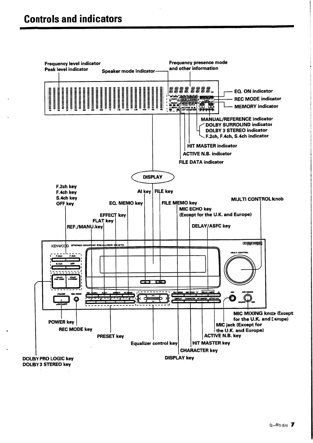
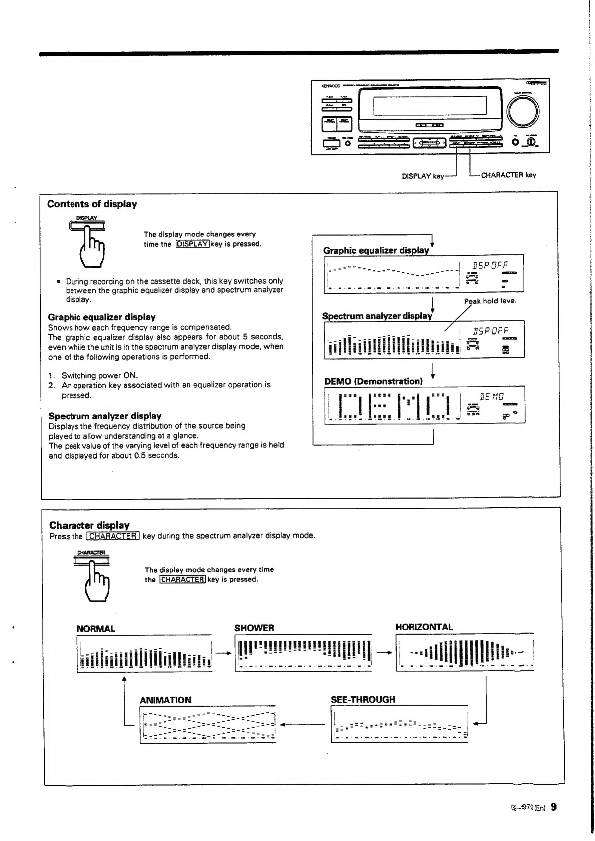
Kenwood GE-970 User manual

GRAPHIC
EQUALIZER
GE-970
INSTRUCTION
MANUAL
KENWOOD
CORPORATION
When
you
play
a
music
source
while
this
unit
is
connected
to
your
system,
always
turn
the
power
of
this
unit
ON
regardless
of
whether
you
use
the
graphic
equalizer
functions
or
not.
(The
audio
signal
reproduced
by
the
source
playback
compo-
nent
is
sent
to
the
amplifier
by
passing
through
this
unit.
Therefore,
the
music
source
cannot
be
listened
to
unless
the
power
of
this unit
is
ON.)
B60-1388-00
94/12
1110987654
oe
M,
x)
Gl
3/12
11109876
i
H
i
?
;
i

Introduction
i
NN
eo
eh)
Your
choice
of
this
product
indicates
that
you
are
a
devotee
to
excellence
in
sound
reproduction.
We
appreciate
your
patronage
and
take
pride
in
the
long
tradi-
tion
of
quality
components
that
our
company
represents.
So
that
you
can
get
the
most
out
of
your
unit,
we
suggest
that
you
take
the
time
to
read
through
this
manual
before
you
hook
up
and
operate
your
system.
This
will
acquaint
you
with
oper-
ating
features
and
system-connection
considerations
so
that
your
listening
pleasure
will
be
enhanced
right
from
the
start.
You
will
notice
that
in
all
aspects
of
planning,
engineering,
styling,
operating
convenience
and
adaptability
we
have
sought
to
anticipate
your
needs
and
desires.
Keep
this
manual
handy
for
future
reference.
For
your
records
Record
the
serial
number,
found
on
the
back
of
the
unit,
in
the
spaces
designated
on
the
warranty
card,
and
in
the
space
provided
below.
Refer
to
the
model
and
serial
numbers
whenever
you
call
upon
your
dealer
for
information
or
service
on
this
product.
Mode!
__________
Seria!
Number
Unpacking
Unpack
the
unit
carefully
and
make
sure
that
all
accessories
are
put
aside
so
they
will
not
be
lost.
Examine
the
unit
for
any
possibility
of
shipping
damage.
if
your
unit
is
damaged
or
fails
to
operate,
notify
your
dealer
immediately.
If
your
unit
was
shipped
to
you
directly,
notify
the
shipping
company
without
delay.
Only
the
consignee
(the
person
orcompany
receiving
the
unit)
can
file
a
claim
against
the
carrier
for
shipping
damage.
We
recommend
that
you
retain
the
original
carton
and
pack-
ing
materials
for
use
should
you
transport
or
ship
the
unit
in
the
future.
Contents
A
Safety
precautions
A\
IMPORTANT
SAFEGUARDS
System
connections
Controls
and
indicators
Operation
of
graphic
equalizer
Contents
of
display
Character
display
Demonstration
procedure
Operation
of
Al
AUTO
(for
CD
play
only)...
Operation
of
Al
FOCUS
(for
CD
play
only)
....
Storing
optimum
equalizer
curve
(Al
FILE)
Playback
by
recalling
a
stored
equalizer
curve
Operation
of
MANUAL/REFERENCE
feature
Equalizer
pattern
list
Fine
adjustment
of
each
frequency
band
{Graphic
mode)
User-preset
of
user-created
pattern
(M-1
to
M-5)
How
touse
the
REC
MODE
key
Bass
Compensation
2
GE-370
fn)
Caution:
Read
the
pages
marked
Lv
carefully
to
ensure
safe
operation.
AC
plug
adaptor
(except
for
U.K.,
Australia
and
Europe)
For
the
unit
with
a
European
AC
plug
in
areas
other
than
Europe.
Surround
Modes
and
presence
modes
Speaker
layout
DOLBY
SURROUND
Operation
of
Dolby
Surround
playback
..
DOLBY
3
STEREO
DOLBY
3
STEREO
adjustment
DOLBY
3
STEREO
playback
Presence
Y
Presence
playback
Combination
of
presence
and
environmental
sound
(F.
4ch
only)
To
turn
presence
effect
OFF
To
record
with
presence
effect
Let's
sing
Regular
MIC
MIXING
Using
HIT
MASTER
Singing
with
echo
Song
Recording
In
case
of
difficulty
....
A
Specifications

Before
applying
power
A
Caution:
Read
this
page
carefully
to
ensure
safe
operation.
aL
a
eI
TS
a
SE
For
the
U.S.A.
and
Canada
Important!
Units
shipped
to
the
U.S.A.
and
Canada
are
designed
for
operation
on
120
volts
AC
only.
For
the
United
Kingdom
Important!
Units
shipped
to
the
U.K.
are
designed
for
operation
on
240
volts
AC
only.
The
mains
plug
must
be
removed
from
the
wall
socket
prior
to
any
internal
examination.
The
wires
in
this
mains
lead
are
coloured
in
accordance
with
the
following
code:.
Neutral
The
wiresin
this
mains
lead
must
be
connected
to
the
terminals
in
the
plug
as
follows:
Wire
colour
Plug
terminal
marking
N
or
Black
L
or
Red
Blue
to
Neutral
Plug
Notes:
______________
1.
If
a
13-amp
plug
is
used,
this
must
be
fitted
with
a
13-amp
fuse.
2.
If
a
3-pin
plug
with
earthing
contact
is
used,
no
wire
must
be
connected
to
the
E
terminal.
Safety
precautions
WARNING:
TO
PREVENT
FIRE
OR
ELECTRIC
SHOCK,
DO
NOT
EXPOSE
THIS
APPLIANCE
TO
RAIN
OR
MOISTURE.
CAUTION
RISK
OF
ELECTRIC
SHOCK
THE
LIGHTNING
FLASH
WITH
ARROWHEAD
SYMBOL,
WITHIN
AN
EQUILATERAL
TRIAS
GLE,
IS
INTENDED
TO
ALERT
THE
USER
TO
THE
PRESENCE
OF
UNINSULATED
“DANGEROUS
VOL-
TAGE”
WITHIN
THE
PRODUCT'S
ENCLOSURE
THAT
MAY
BE
OF
SUFFICIENT
MAGNTUDE
TO
CONSTITUTE
A
RISK
OF
ELECTRIC
SHOCK
TO
PERSONS.
THE
EXCLAMATION
POINT
WITHIN
AN
EQUILATERAL
TRIANGLE
IS
INTENDED
TO
ALERF
THE
USER
TO
THE
PRESENCE
OF
IMPORTANT
OPERATING
AND
MAINTENANCE
(SERVICINCS)
IN-
STRUCTIONS
IN
THE
LITERATURE
ACCOMPANYING
THE
APPLIANCE.
CAUTION:
TO
REDUCE
THE
RISK
OF
ELECTRIC
SHOCK,
DO
NOT
REMOVE
COVER
(OR
BACK).
NO
USER-SERVICEABLE
PARTS
INSIDE,
REFER
SER-
DONCT
OREN
VICING
TO
QUALIFIED
SERVICE
PERSONNEL.
For
Australia
and
Europe
Important!
Units
shipped
to
Australia
are
designed
for
operation
on
240
V
AC
only.
Units
shipped
to
Europe
are
designed
for
operation
on
230
V
AC
only.
For
other
countries
Important!
Units
shipped
to
countries
other
than
the
above
countries
areequipped
with
an
AC
voltage
selector
switch
on
the
rear
panel.
Refer
to
the
following
paragraph
for
the
proper
setting
of
this
switch.
AC
voltage
selection
This
unit
operates
on
110-120
or
220-240
volts
AC.
The
AC
voltage
selector
switch
Type
A
or
Type
B
on
the
rear
panel
is
set
to
the
voltage
that
prevails
in
the
area
to
which
the
unit
is
shipped.
Before
connecting
the
power
cord
to
your
AC
outlet,
make
sure
that
the
setting
position
of
this
switch
matches
your
line
voltage.
If
not,
it
must
be
set
to
your
voltage
in
accordance
with
the
following
direction.
AC
voltage
selector
switch
_
Type
A
Ll
AC110-
«>
AC220-
120
V
~
240
V
~
—_
<_
AC
110-
AC
220V~
AC
230-240V
~
120V~
Move
switch
lever
to
match
your
line
voltage
with
a
small
screwdriver
or
other
pointed
tool.
Note:
Our
warranty
does
not
cover
damage
caused
by
excessive
line
voltage
due
to
improper
setting
of
the
AC
voltage
selector
switch.
GE-GO
(En)
3

IMPORTANT
SAFEGUARDS
Please
read
all
of
the
safety
and
operating
instructions
before
operating
this
appliance.
Adhere
to
all
warnings
on
the
appliance
and
in
the
instruction
manual.
Follow
ali
the
safety
and
operating
instructions.
These
safety
and
operating
instructions
should
be
retained
for
future
reference.
1.
Power
sources
—
The
appliance
should
be
connected
to
a
power
supply
only
of
the
type
described
in
the
instruction
manual
or
as
marked
on
the
appliance.
If
you
are
not
sure
of
the
type
of
power
supply
to
your
home,
consult
your
appliance
dealer
or
local
power
company.
For
appliances
intended
to
operate
from
battery
power,
or
other
sources,
refer
to
the
instruction
manual.
2.
Power-cord
protection
—Power-supply
cords
should
be
routed
so
that
they
are
not
likely
to
be
walked
on
or
pinched
by
items
placed
upon
or
against
them,
pay
particular
attention
to
cords
at
plugs,
convenience
receptacles,
and
the
point
where
they
exit
from
the
appliance.
Never
pull
or
stretch
the
cord.
3.
CAUTION
—-
Polarization
-—
This
appliance
may
be
equipped
with
a
polarized
alternating-current
line
plug
(a
plug
having
one
blade
wider
than
the
other).
This
plug
will
fit
into
the
power
outlet
only
one
way.
This
is
a
safety
future.
If
you
are
unable
to
insert
the
plug
fully
into
the
outlet,
try
reversing
the
plug.
If
the
plug
should
still
fail
to
fit,
contact
your
electrician
to
replace
your
obsolete
outlet.
Do
not
defeat
the
safety
purpose
of
the
polarized
plug.
4.
Ventilation
-
Slots
and
openings
in
the
cabinet
are
provided
for
ventilation
and
to
ensure
reliable
operation
of
the
appliance
and
to
protect
it
from
overheating,
and
these
openings
must
not
be
blocked
or
covered.
The
appliance
should
be
situated
so
that
its
location
or
position
does
not
interfere
with
its
proper
ventilation.
To
maintain
good
ventilation,
do
not
put
records
or
a
table-
cloth
on
the
appliance.
Place
the
appliance
at
least
10
cm
away
from
the
walls.
Do
not
use
the
appliance
on
a
bed,
sofa,
rug
or
similar
surface
that
may
block
the
ventilation
openings.
This
appliance
should
not
be
placed
ina
built-in
installation
such
as
a
bookcase
or
rack
unless
proper
ventilation
is
provided
or
the
manufacturer's
instructions
have
been
adhered
to.
5.
Waterand
moisture
-
The
appliance
should
not
be
used
near
water
-
for
example,
near
a
bathtub,
washbowl,
kitchen
sink,
laundry
tub,
in
a
wet
basement,
or
near
a
swimming
pool,
etc.
GE-970
(En)
|
|
\
{
i
A
Caution:
Read
this
page
carefully
to
ensure
safe
operation.
6.
Temperature
-
The
appliance
may
not
function
properly
if
used
at
extremely
low,
or
freezing
temperatures.
The
ideal
ambient
temperature
is
above
+5°C
(41°F).
7.
Heat
-The
appliance
should
be
situated
away
from
heat
sources
such
as
radiators,
heat
registers,
stoves,
or
other
appliances
(including
amplifiers)
that
produce
heat.
8.
Electric
shock
—
Care
should
be
taken
so
that
objects
do
not
fall
and
liquid
is
not
spilled
into
the
enclosure
through
openings.
If
a
metal
objects,
such
as
a
hair
pin
or
a
needle,
comes
into
contact
with
the
inside
of
this
appliance,
a
dangerous
electric
shock
may
result.
For
families
with
children,
never
permit
children
to
put
anything,
especially
metal,
inside
this
appliance.
9.
Enclosure
removal
—
Never
remove
the
enclosure.
If
the
internal
parts
are
touched
accidentally,
aserious
electric
shock
might
occur.
10.Magnetic
fields
-
Keep
the
appliance
away
from
sources
of
magnetic
fields
such
as
TV
sets,
speaker
systems,
radios,
motorized
toys
or
magnetized
objects.
11.Cleaning
-—
Unplug
this
appliance
from
the
wall
outlet
before
cleaning.
Do
not
use
volatile
solvents
such
as
alcohol,
paint
thinner,
gasoline,
or
benzine,
etc.
to
clean
the
cabinet.
Use
a
clean
dry
cloth.
12.
Accessories
~
Do
not
place
this
appliance
on
an
umstable
cart,
stand,
tripod,
bracket,
or
table.
The
appliance
may
fall,
causing
serious
injury
to
a
child
or
adult,
and
serious
damage
to
the
appliance.
Use
only
with
a
cart
stand,
tripod,
bracket,
ortable
recommended
by
the
manuiescturer,
or
sold
with
the
appliance.
Any
mounting
of
the
appliance
should
follow
the
manufacturer's
instructions,
ani
should
use
a
mounting
accessory
recommended
by
the
manufacturer.
An
appliance
and
cart
combinatior
should
be
moved
with
care.
Quick
stops,
excessive
force,
and
uneven
surfaces
may
cause
the
appliance
and
cart
combination
to
overturn.

13.
14.
15.
16.
17.
Lightning
—
For
added
protection
for
this
appliance
during
a
lightning
storm,
or
when
it
is
left
unattended
and
unused
for
long
periods
of
time,
unplug
it
from
the
wall
outlet
and
disconnect
the
antenna
or
cable
system.
This
will
prevent
damage
to
the
appliance
due
to
lightning
and
power-line
surges.
Abnormal
smell
-
[f
an
abnormal
smell
or
smoke
is
detected,
immediately
turn
the
power
OFF
and
unplug
the
appliance
from
the
wall
outlet.
Contact
your
dealer
or
nearest
service
center.
_
POWER
OFF!
Se
Damage
requiring
service
—
The
appliance
should
be
serviced
by
qualified
service
personnel
when:
A.
The
power-supply
cord
or
the
plug
has
been
damaged.
B.
Objects
have
fallen,
or
liquid
has
been
spilled
into
the
appliance.
C.
The
appliance
has
been
exposed
to
rain
or
water.
D.
The
appliance
does
not
appear
to
operate
normally
by
following
the
instruction
manual.
Adjust
only
those
controls
that
are
covered
by
the
instruction
manual
as
an
improper
adjustment
of
other
controls
may
result
in
damage
and
will
often
require
extensive
work
by
a
qualified
technician
to
restore
the
appliance
to
its
normal
operation.
E.
The
appliance
has
been
dropped,
or
the
enclosure
damaged.
F.
Theappliance
exhibits
a
marked
change
in
performance.
Servicing
—
The
user
should
not
attempt
to
service
the
appliance
beyond
that
described
in
the
instruction
manual.
All
other
servicing
should
be
referred
to
qualified
service
personnel.
Outdoor
antenna
grounding
-
If
an
outside
antenna
is
Connected
to
the
appliance,
be
sure
the
antenna
system
is
grounded
so
as
to
provide
some
protection
against
voltage
surges
and
built
up
static
charges.
Article
810
of
the
National
Electrical
Code
ANSI/
NFPA
70,
provides
information
with
respect
to
proper
grounding
of
the
mast
and
supporting
structure,
grounding
of
the
lead-in
wire
to
an
antenna
discharge
unit,
size
of
grounding
conductors,
location
of
antenna
discharge
unit,
connection
to
grounding
electrodes,
and
requirements
for
the
grounding
electrode.
See
Figure.
EXAMPLE
OF
ANTENNA
GROUNDING
AS
PER
NATIONAL
ELECTRICAL
CODE
ANTENNA
LEAD
IN
WIRE
>»
DISCHARGE
UNIT
U
ELECTRIC
(NEC
SECTION
810-20)
SERVICE
EQUIPMENT
LAY,
GROUNDING
CONDUCTORS
(NEC
SECTION
810-21)
GROUND
CLAMP
v=t——
POWER
SERVICE
GROUNDING
ELECTRODE
SYSTEM
{NEC
ART
250,
PART
H)
NEC
-
NATIONAL
ELECTRICAL
CODE
A
Caution
:
Read
this
page
carefully
to
ensure
safe
operation.
18.Power
lines
—
An
outside
antenna
system
should
not
be
located
in
the
vicinity
of
overheated
power
lines
or
other
electric
light
or
power
circuits,
or
where
it
can
fall
into
such
power
lines
or
circuits.
When
installing
an
outside
antenna
system,
extreme
care
should
be
taken
to
keep
from
:
touching
such
power
lines
or
circuits
as
contact
with
them
i
might
be
fatal.
19.AC
outlets
-
Do
not
connect
other
audio
equipment
with
a
power
consumption
larger
than
that
specified
to
the
AC
outlet
on
the
rear
panel.
Never
connect
other
electrical
appliances,
such
as
an
iron
or
toaster,
to
it
to
prevent
fire
or
electric
shock.
20.
Overloading
~
Do
not
overload
wall
outlets,
extension
cords,
or
integral
convenience
receptacles
as
this
can
result
in
a
risk
of
fire
or
electric
shock.
21.
Attachment
-
Do
not
use
attachments
not
recommended
by
the
appliance
manufacturer
as
they
may
cause
hazards.
22.
Replacement
parts—When
replacementparts
ale
required,
be
sure
the
service
technician
has
used
replacement
parts
specified
by
the
manufacturer
or
have
the
same
characteristics
as
the
original
parts.
Unauthorized
substitutions
may
result
in
fire,
electric
shock,
or
other
hazards.
23.
Safety
check
-
Upon
completion
of
any
service
or
repairs
to
this
appliance,
ask
the
service
technician
to
perform
safety
checks
to
determine
that
the
applianceis
in
proper
operating
condition.
Notes:
1.
!tem3is
not
required
except
for
grounded
or
polarizey
€&qQuipment.
2.
Item
17
and
18
are
not
required
except
for
units
jroovided
with
antenna
terminals.
3.
Item
17
complies
with
UL
in
the
U.S.A.
€-B70(En)
5

System
connections
Make
connection
as
shown
below.
When
connecting
the
related
system
components,
refer
also
to
the
instruction
manuals
of
the
related
components.
Do
not
plug
in
the
power
lead
until
all
connections
are
completed.
KENWOOD
integrated
amplifier
(A-97,
A-87)
Shape
of
AC
outlet
AUSTRALIA
x1
Unit
destination
Unplug
the
shorting
pins
from
the
ADAPTOR
jacks
and
connect
the
(For
U.K.
and
Europe)
SS
To
"Switched"
AC
outlet
on
AC
voltage
‘
Europe
|
selector
switch
the
amplifier
:
xe
(Except
for
U.K.
rear
panel
Other
countries
and
Europe)
For
the
connection
of
the
SYSTEM
CONTROL
terminals
and
power
cords,
refer
to
connection
diagram
of
the
main
sustem.
¢
Do
not
connect
other
amplifier
than
the
KENWOOD
A-97
and
A-87
amplifier
to
the
ADAPTOR
(DUAL-FUNCTION
CONNECTERS)
jacks.
©
Do
not
connect
the
LVD-97
to
the
AC
OUTLET
on
the
rear
panel.
(For
the
K-99LD
system.)
System
control
connection
cuick
When
unplugging
the
cord
When
connected
to
the
main
system,
system
operation
x
O
ee
2
such
as
remote
contro!
is
made
possible.
For
details,
refer
to
the
instruction
manual
of
the
main
system.
If
your
armplifier
or
receiver
is
not
equipped
with
the
SYSTEM
CONTROL
terminals,
do
not
connect
anything
Push
to
any
SYSTEM
CONTROL
terminal.
Do
not
connect
the
unit
in
any
system
configuration
Insert
securoly
sneilirt
¢hices
other
than
specified.
*
Be
sure
to
insert
the
system
control
cord
plugs
fully
int)
the
SYSTEM
CONTROL
terminals.
®}f
the
system
contro!
cord
and
audio
cords
are
not
conneccted
properly,
the
automatic
system
governing
remote
contro
and
system
functions
will
not
operate.
Notes:
1.
Connectall
cords
firmly.
If
connections
are
loose,
there
could
be
loss
of
sound
or
noise
produced.
2.
When
plugging
and
unplugging
connection
cords,
be
sure
to
first
remove
the
power
cord
from
the
AC
outlet.
Plugging/unpluy
ging
connection
cords
without
removal
of
the
power
cord
can
cause
malfunctions
or
damage
to
the
unit.
3.
Do
not
connect
up
a
power
source
which
is
larger
than
that
indicated
on
the
socket
at
the
rear
of
the
unit.
6
GE-970
En)

Controls
and
indicators
Ran
PS
TS
IE
Frequency
levei
indicator
Frequency
presence
mode
Peak
level
indicator
and
other
information
Speaker
mode
indicator
RRa8
Be
eee
EQ.
ON
indicator
REC
MODE
indicator
MEMORY
indicator
MANUAL/REFERENCE
indicator
DOLBY
SURROUND
indicator
DOLBY
3
STEREO
indicator
F.2ch,
F.4ch,
S.4ch
indicator
HIT
MASTER
indicator
ACTIVE
N.B.
indicator
FILE
DATA
indicator
as
>
F.2ch
key
F.4ch
key
Al
key
|
FILE
key
S.4ch
key
OFF
key
EQ.
MEMO
key
FILE
MEMO
key
MULTLCON
TROL
Inge
MIC
ECHO
key
EFFECT
key|
—
(Except
for
the
U.K.
and
Europe)
FLAT
key
REF./MANU.key
DELAY/ASFC
key
ay
MIC
MIXING
knob
(Except
POWER
key
__
for
the
U.K.
and
Europe)
REC
MODE
key
the
UK.
ancl
Eero)
PRESET
key
ACTIVE
N.B.
key
Equalizer
control
key
HIT
MASTER
key
CHARACTER
key
DOLBY
PRO
LOGIC
key
DISPLAY
key
DOLBY
3
STEREO
key
a-S70
(En
F
i
:
H
}
a

Operation
of
graphic
equalizer
Re
ie
a
a
a
a
aE
Te
a
TR
This
unit
is
a
near-professional
type
graphic
equalizer
which
allows
fine
adjustments
of
frequency
bands.
It
not
only
provides
acoustic
compensation
for
the
characteristics
of
your
listening
room,
but
also
reproduces
each
music
source
with
adequate
tone
using
the
following
Al
(Artificial
intelligence)
features.
1.
DEMO
(Demonstration)
Displays
various
equalizer
curves
visually
in
sequence
together
with
the
actual
sound
effect
of
each
curve
as
an
audible
|
demonstration.
|
2.
Al-AUTO
(available
only
for
CD
play)
When
playing
a
CD
with
the
presence
effect
OFF,
checks
the
contents
recorded
on
the
CD
automatically,
and
sets
the
optimum
equalizer
pattern
and
LINEAR
ACOUSTIC
control
knob
on
the
amplifier
(A-87,
A-97)
according
to
the
CD.
(Refer
to
page
10.)
3.
Al-FOCUS
(available
only
for
CD
play)
;
When
playing
a
CD
with
the
presence
effect
ON,
checks
the
contents
recorded
on
the
CD
with
respect
to
the
presence
:
;
mode
selected,
and
sets
the
optimum
equalizer
pattern
and
ASFC
setting
and
LINEAR
ACOUSTIC
control
knob
on
\
the
amplifier
(A-87,
A-97)
according
to
the
CD
and
the
presence
mode
selected.
(For
the
ASFC
(Acoustic
Surround
Field
Control),
refer
to
page
25.)
4.
AI-LINK
(available
for
all
input
sources)
When
the
presence
mode
is
selected,
optimum
equalizer
curve
for
this
mode
is
selected
automatically
to
enhance
the
|
presence
effect.
The
LINEAR
ACOUSTIC
control
knob
on
the
amplifier
(A-87,
A-97)
is
set
automatically
according
to
the
selected
sound
field.
5.
AI
FILE
(available
only
for
CD
play)
The
equalizer
curve
set
with
the
Al
feature
and
the
balance
set
with
the
LINEAR
ACOUSTIC
control
of
the
amplifier
can
be
stored
for
up
to
60
Compact
Discs.
When
a
CD
with
its
data
stored
in
the
Al
File
is
played,
this
function
makes
the
time
of
Al
setting
(about
30
seconds)
unnecessary.
If
a
presence
mode
(F.2ch,
F.4ch,
S.4ch)
is
selected,
the
optimum
ASFC
(the
setting
factor
determining
the
sound
expansion)
is
also
set
automatically.
6.
MANUAL/REFERENCE
modes
REFERENCE:
Ten
exemplary
patterns
have
been
preset
at
the
factory.
(Refer
to
page
14.)
MANUAL:
Five
preset
patterns
have been
factory-preset
for
this
mode,
too.
In
this
mode,
it
is
also
possible
to
preset
(assign)
equalizer
patterns
created
by
the
user
in
place
of
the
factory
presets.
7.
CHARACTER
In
the
spectrum
analyzer
display
mode,
the
level
of
the
music
being
played
and
changes
of
frequency
distribution
with
four
different
patterns
are
displayed.
SPE.
ANA
1:
NORMAL
Normal
spectrum
analyzer
display
2:
SHOWER
Reversed
normal
spectrum
analyzer
display
with
the
normal
peak
hold
levels
display
3.
HORIZONTAL
Displays
right
and
left
levels
with
the
frequency
band
in
vertical
axis
and
level
in
horizontal
axis.
4;
SEE-THROUGH
Displays
peak
and
peak
hold
levels
only.
ANIMATION
Displays
various
patterns
regardless
of
the
freguency
or
level.
8.
REC
MODE
(For
car
stereo,
headphone
stereo)
The
equalizer
pattern
displayed
is
also
applied
to
the
sound
recorded
on
tape.
In
addition,
a
recording
equalizer
curve
“CAR’,
which
records
sound
so
that
optimum
balance
is
obtained
when
the
tape
is
played
on
a
car
stereo,
and
recording
equalizer
curve
“HEADPHONE
ST.”,
which
records
sound
so
that
optimum
balance
is
obtained
when
‘the
tape
is
played
on
a
headphone
stereo,
are
provided.
By
selecting
one
of
these
two
REC
MODES
together
with
an
equalizer
pattern
of
Al-AUTO
or
MANUAL/REFERENCE,
both
effects
can
be
applied
to
the
recording,
so
that
thetape
simulates
the
sound
of
a
listening
room
through
a
car
stereo
or
headphone
stereo.
(Refer
to
page
16.)
Al:
Artificial
Intelligence.
The
Al
is
capable
of
adjusting
the
tone
automatically
according
to
the
source
and
music
categories
8
GE970
«En

DISPLAY
key
CHARACTER
key
Contents
of
dispiay
DISPLAY
The
display
mode
changes
every
time
the
[DISPLAY
|key
is
pressed.
Graphic
equalizer
display
¢
During
recording
on
the
cassette
deck,
this
key
switches
only
between
the
graphic
equalizer
display
and
spectrum
analyzer
display.
Graphic
equalizer
display
Shows
how
each
frequency
range
is
compensated.
The
graphic
equalizer
display
also
appears
for
about
5
seconds,
even
while
the
unit
is
in
the
spectrum
analyzer
display
mode,
when
one
of
the
following
operations
is
performed.
1.
Switching
power
ON.
2.
Anoperation
key
associated
with
an
equalizer
operation
is
pressed.
DEMO
(Demonstration)
A
Baz
eeag
i
2S
j
uze
:
zEg
EES
eo
eee
Sree
Se.
EER
i
Spectrum
analyzer
display
seef.
:
Displays
the
frequency
distribution
of
the
source
being
played
to
allow
understanding
at
a
glance.
The
peak
value
of
the
varying
level
of
each
frequency
range
is
held
and
displayed
for
about
0.5
seconds.
Character
display
Press
the
[CHARACTER]
key
during
the
spectrum
analyzer
display
mode.
CHARACTER
_
The
display
mode
changes
every
time
the
[CHARACTER]
key
is
pressed.
NORMAL
SHOWER
HORIZONTAL
G-2701En
9
i
t
i
sin
Dn
nS
BE
SREB
ei
SO
a
a
mink

Operation
of
graphic
equalizer
@
Demonstration
procedure
This
feature
makes
it
possible
to
check
the
equalizer
effects
both
visually
and
audibly.
@
Select
an
input
source
eas
——m
SPECTRUM
ANALYZER
DEMO
(Demonstration)
ee
a
Al
(AUTO)
@
Play
the
source.
AI
LINK
@®
Select
DEMO
with
the
DISPLAY
key.
REFERENCE?
(R1)
1~5
@
Demonstration
is
repeated
in
the
following
cycle.
REFERENCE2
(R2)
1~5
MANUAL
(M)
1~5
e
Press
the
key
to
stop
demonstration.
REC
MODE
*
During
Al
LINK
demonstration,
the
Surround
mode
also
changes.
Selecting
"DEMO"
starts
e
|fthe
demonstration
is
started
while
the
unit
is
in
the
Surround
mode,
the
Surround
sequential
demonstration.
mode
will
be
turned
OFF
during
demonstration.
@
Operation
of
Al
AUTO
(for
CD
play
only)
When
playing
a
CD
with
the
presence
effect
OFF,
the
equalizer
curve
suitable
for
a
specific
disc
is
set
automatically
by
simply
pressing
the
Al
key.
1
Place
a
disc
in
the
CD
player.
jemas
Track
Nos
in
disc
are
TRACK
lights
up.
:
indicated.
Check
that
the
presence
mode
is
OFF.
2
Press
the
Al
key.
Blinks
Lights
up.
\_!
7)
about
30
sec.
—
ends
nalyzer
displa
Completes
and
stops
in
Spectiunmnenaly:
el
about
30
seconds.
Graphic
equalizer
display
¢
Wait
for
about
30
seconds
untiliEQ.ON|
and
light
up.
©
The
LINEAR
ACOUSTIC
control
knob
on
the
amplifier
(A-87,
A-
97)
is
set
automatically.
The
playback
starts
automatically.
Note:
In
step
2,
the
other
keys
than
the
and
the
[POWER]
key
do
not
operate.
To
cancel
Ai
AUTO
e
goes
off.
¢
If
it
is
cancelled
during
Al
AUTO
setting
operation,
te
last
pattern
selected
before
is
displayed.
¢
Al
AUTO
is
canceled
also
when
the
disc
tray
is
openc,
Cancellation
during
setting
Cancellation
during
play
10
Ges706n)
i
i
i

Al
key
MULTI
CONTROL
knob
Presence
mode
keys
@
Operation
of
Al
FOCUS
(for
CD
play
only)
When
playing
a
CD
with
the
presence
effect
ON,
the
delay
time,
presence
volume
(reverberation
level
)
and
equalizer
curve
are
set
automatically
by
simply
pressing
the
Al
key.
CD
player
display
|
RESIS
:
in
disc
are
!
7.
indicated.
Lights
up.
tf
ong
|
Place
a
disc
in
the
CD
player.
2
Select
the
desired
presence
mode.
3
Select
a
sound
field.
Mode
name
display
MULT
CONTROL
“PN
4
Press
the
Al
key.
®
The
ASFC
(Acoustic
Surround
Blinks
Lights
up.
Field
Control)
and
an
equalizer
\\_!
/_
about
30
sec.
pattern
are
set
according
tothe
—
=
presence
mode
selected.
7HIN~
Ciiniciasigndeube
*
The
LINEAR
ACOUSTIC
control
about
0
encode
knob
of
the
amplifier
(A-87,
A-
7
97)
is
set
automatically
accord-
ing
to
the
selected
sound
field.
e
Wait
for
about
30
seconds
until
[EQ.ONJand
[Al]
light
up.
©
Playback
starts
automatically.
Spectrumanalyzer
display
Graphic
equalizer
display
Note:
In
step
4,
the
other
keys
than
the
and
the
[POWER]
key
do
not
operate.
To
cancel
Al
FOCUS
.
[Al]
goes
off.
e
|f
it
is
cancelled
during
At
FOCUS
setting
operation,
the
last
pattern
selected
before
is
displayed.
Al
FOCUS
is
cancelled
also
when
the
disc
tray
of
the
CD
player
is
opened.
Cancellation
during
setting
Cancellation
during
play
Geen
19
:
i
Leth
nitrated
nme
sei
thc
ipsa
ae
RE
Nace
CE
ta
hE
ARDS
cm
aaa

Operation
of
graphic
equalizer
Presence
mode
keys
@
Storing
optimum
equalizer
curve
(Al
FILE)
The
graphic
equalizer
curves
set
with
the
Al
can
be
stored
in
memory
for
up
to
60
discs.
When
a
CD
with
its
data
stored
in
the
Al
File
is
played,
itis
not
necessary
to
wait
the
Al
setting
because
these
settings
are
recalled
automati-
cally.
1
Place
a
disc
in
the
CD
player.
2
Press
the
Al
key.
The
optimum
equalizer
curve
is
selected
in
about
30
seconds.
Blinks
Lights
up
~~!
/
UApprox.
30
sec.
=
=
7\IN~
ends
During
sampling
After
sampling
3
Press
the
FILE
MEMO
key.
Lights
up
*
The
equalizer
curves
set
with
the
Al
feature
can
be
stored.
*
Data
ofup
to
60
CDs
can
be
stored.
When
data
of
the
61st
disc
is
stored,
the
data
of
the
CD
with
the
least
frequency
of
use
is
cleared.
(By
checking
the
last
time
each
data
was
used,
the
data
which
has
not
been
used
for
the
tongest
period
of
time
is
cleared.)
12
GE970
¢)
FILE
key
FILE
MEMO
key
MULTI
CONTROL
knob
@
Playback
by
recalling
a
stored
equalizer
curve
(Al
FILE)
Press
the
FILE
key.
Lights
up.
Keep
the
FILE
key
OFF
when
it
is
not
required
to
recall
the
Al
FILE
data.
Place
a
CD
with
already
stored
data.
Lights
up.
[BSP
OFF
—
une
gs
The
FILE
DATA
indicator
lights
when
CD
the
data
of
which
has
already
been
stored
is
placed
and
the
tray
is
closed.
To
play
with
a
presence
mode,
also
select
the
presence
mode.
@
Select
a
mode.
@
Select
a
sound
field.
MULT
CONTROL
a5
FY
==»
U
3
Play
the
disc.
The
stored
equalizer
curve
is
recalled
andttre
playback
starts.
e
If
apresence
mode
has
been
selected,
the
ASFC
(the
setisag
factor
determining
the
sound
expansion)
is
also
set
uto-
matically.
¢
The
optimum
LINEAR
ACOUSTIC
control
balance
(the
b
al-
ance
of
volume
between
the
main
and
omnidirectional
sjesk-
ers)
is
also
set
automatically.
i
:

REF./MANU.
key
Operation
of
MANUAL/REFERENCE
feature
This
feature
makes
it
possible
to
recall
one
of
fifteen
preset
equalizer
patterns
in
a
simple
manner.
The
equalizer
patterns
of
the
MANUAL
mode
(M-1
to
M-5)
are
mainly
for
use
in
playback
with
Surround
effect.
1
Select
an
input
source
on
the
amplifier.
Remote
control
unit
2
Play
the
music
source.
3
Press
the
EFFECT
key.
Lights
up.
Remote
control
unit
4
Select
an
equalizer
pattern.
@
Set
to
MANUAL
or
REFERENCE
1,
2.
@
Press
the
key
for
the
desired
pattern.
(Refer
to
the
equalizer
pattern
list
on
page
14).
REF.
/MANU.
4
2
3
4
s
Th
=
hy
|
BSPOFF
Example
when
“3”
is
selected
in
the
MANUAL
mode.
MANUAL
REFERENCE-1
Remote
control
unit
REFERENCE-2
Patterns
are
switched
every
time
the
|M.
CALL]
key
is
pressed.
To
cancel
the
equalizer
effect
How
to
use
FLAT
key
Reemain
ON.
e
The
pattern
being
displayed
remains
the
same.
e
Pressing
the
[FLAT]
key
flattens
the
curve.
&-270
(En)
13
;
i
i
:
i
;
H
i
i
Hy
i
Sesame
cit
tii
tN
nan
ASC
SSE
AE

Operation
of
graphic
equalizer
@
Equalizer
pattern
list
15
kinds
of
preset
equalizer
patterns
can
be
recalled
easily.Select
the
optimum
pattern.
REFERENCE
17
(R1-1
to
5)
equalizer
patterns
(Popular,
Fusion)
Makes
the
fusion
music
or
the
vocal
of
pop
music
distinct
while
providing
optimum
compensation
for
the
low
and
high
frequencies.
(Rock)
Makes
the
vocal
of
rock
music
distinct
while
providing
optimum
compensation
for
the
low and
high
fre-
quencies.
(Jazz)
Makes
the
midrange
frequencies
in
jazz
music,
in-
cluding
the
vocal,
piano
and
sax
distinct,
while
pro-
viding
optimum
compensation
for
the
low
and
high
frequencies.
(Classic)
Provides
well,
balanced
classical
music
by
compen-
sating
the
low,
midrange
and
high
frequencies.
(Movie)
Makes
the
dialogue
distinct
while
providing
optimum
compensation
for
the
low
and
high
frequencies.
REFERENCE
2
(R2-1
to
5)
equalizer
patterns
(Popular,
Fusion)
Reproduces
crisp
sound
with
distinct
vocal
and
enhanced
low
and
high
frequencies.
(Rock)
Reproduces
powerful
sound
with
distinct
vocal
and
enhanced
low and
high
frequencies
of
the
bass,
guitar
and
drums.
(Jazz)
Makes
the
vocal,
piano
and
sax
more
distinct
while
providing
powerful,
full
bass
and
drum
sound
by
enhancing
the
low
and
high
frequencies.
(Classic)
Reproduces
dynamic
sound
with
a
full
scale
through
heavy
low,
powerful
midrange
and
unrestrained
high
frequencies.
(Movie)
Makes
the
dialogue
distinct
while
enhancing
the
low
and
high
frequencies
for
a
powerful
sound
with
full
atmosphere
of
presence.
14
GE970
€n)
MANUAL
(M-1
to
M-5)
equalizer
patterns
User-set
curves
can
be
stored
in
this
mode.
(Popular,
Fusion)
Makes
the
fusion
music
or
the
vocal
of
pop
music
distinct
while
making
the
low
and
high
frequencies
clear
by
enhancing
them.
;
(Rock)
Makes
the
vocal
of
rock
music
distinct
and
enhanced
the
low
and
high
frequencies.
(Jazz)
Makes
the
jazz
vocal
and
drums
distinct,
while
making
the
low
and
high
frequencies
clear
by
en-
hancing
them.
(Classic)
Attenuates
the
low
frequencies
and
enhanced
the
midrange
and
high
frequencies
to
provide
wind
instruments
and
vocals
with
unrestrained
sound.
(Movie)
:
Makes
the
dialogue
distinct
by
attenuating
the
low
and
high
frequencies.
Also
reduces
noise
in
old
movies,
etc.
i
;
d
|
}

i
Fine
adjustment
of
each
frequency
band
(Graphic
mode)
1
Press
the
EFFECT
key
to
set
the
equalizer
to
ON.
Ligh
.
ights
up.
Equalizer
pattern
display
3
Select
the
frequency
band
to
be
adjusted.
To
higher
frequencies
To
lower
frequencies
ah,
Press
the
EQ.
control
keys.
4
Adjust
its
level.
To
increase
To
decrease
Press
the
EQ.
control
keys.
5
For
each
frequency
band
to
be
adjusted,
repeat
steps
3
and
4
above.
EFFECT
key
REF./MANU.
key
Preset
number
keys
EQ.
control
keys
@
User-preset
of
user-created
pattern
(M-1
to
M-5)
1
Create
a
desired
equalizer
pattern.
e
Any
equalizer
pattern
can
be
preset
if
it
is
being
displayed.
°
The
pattern
cannot
be
preset
during
operation
of
Al
AUTO
or
Al
FOCUS.
2
Preset
the
equalizer
pattern
in
the
manual
memory.
@
Press
the EQ.
MEMO
key.
Lights
up.
-
@
Press
one
of
the
preset
number
keys.
41
2
3
4
5
Press
while
[MEMORY
is
lit.
¢
Patternis
preset
under
the
number
of
the
numerickey
pressed.
¢
Up
to
five
patterns
can
be
preset
in
the
same
manner.
e
When
a
pattern
has
previously
been
preset
under
the
numeric
key
pressed,
the
newly
preset
pattern
replaces
the
previous
pattern.
To
return
to
the
initial
pattern
(factory-preset
patterns
M-1
to
M-5
on
page
13)
by
clearingthe
user-
preset
pattern.
@
Select
the
MANUAL
mode.
REF.
/MANU.
@
Press
the
preset
key
where
the
patiern
to
be
cleared
is
preset
for
more
than
5
seconds.
4
ce-970
(En)
45
j
int
Reel
ns
Sat
Mins
NA
AEE
Ninh
ELE
pate
lana

Operation
of
graphic
equalizer
@
How
to
use
the
REC
MODE
key
Use
the
following
function
when
recording
tapes
to
be
played
on
a
car
stereo
or
headphone
stereo.
1
Press
the
EFFECT
key
to
set
the
equalizer
to
ON.
Lights
up.
2
Select
an
input
source
and
the
desired
curve.
¢
Refer
to
page
10
to
15.
3
Select
a
REC
MODE.
REC
MODE
When
you
select
“HEADPHONE
ST.”
Each
press
switches
the
modes.
CAR
(Recording
for
car
stereo)
=
HEADPHONE
ST.
(Recording
for
head
phone
stereo)
OFF
(Curve
before
pressing
REC
MODE)
®
The
pattern
for
car
stereo
recording
or
headphone
stereo
recording
is
combined
with
the
currently-selected
equalizer
pattern.
©
Select
OFF
(indicator
extinguished)
when
the
unit
is
used
as an
ordinary
equalizer
or
for
general
recording
for
other
tapes
than
those
played
on
a
car
stereo
or
a
headphone
stereo.
4
-Play
amusic
source
and
start
recording.
«
Refer
to
the
Instruction
Manual
of
the
main
system.
To
cancel
the
REC
MODE
Press
the
key
to
select
OFF
(indicator
goes
off).
REC
MODE
*
The
display
shows
the
curve
before
synthesis
again.
16
GE-970
cen)
EFFECT
key
REC
MODE
key
ACTIVE
N.B.
key
@
Bass
Compensation
Example:
setected
mode
3
(After
approx.
5
seconds
the
display
returns
to
the
original
state.)
Display:
ANB
1
——
ANB
2
—
ANB3
Goes
off
(OFF)
Each
press
switches
the
modes
in
order.
ACTIVE
N.B.:
Active
Natural
Bass
Circuit
©
The
bass
compensation
mode
is
switched
over
every
time
the
key
is
pressed.
Select
the
desired
mode.
*
When
the
[ACTIVE
N.B]
key
is
ON,
even
if
the
display
is
showing
the
spectrum
analyzer
display,
it
changes
tothe
graphic
equalizer
display
whener
the
equalizer
pattern
charges.
ACTIVE
N.B.
circuit
Automatically
compensates
the
amount
of
bass
appropiate
to
the
content
of
the
music
played.
The
following
tiree
modes
are
available.
@
ANB
1:
Bass
varies
automatically
every
1.6
secons.
@
ANB
2:
Bass
varies
automatically
every
8
second,
@
ANB
3:
Bass
varies
automatically
every
16
seconi,
ANB
1
is
suitable
for
tunes
in
which
the
bass
varies
at
hort
intervals.
Select
ANB
2
or
ANB
3
as
the
variation
interval
lengthens.
The
above
description
serves
only
as
refererce.
Please
play
sound
in
various
modes
and
select
the
one‘hat
suits
your
taste
best.
ae
sind
natch
tt
ae
aren
ibd
aR
ene
ec
tabin
hint
eg
Se

Functions
of
graphic
equalizer
Compensation
for
the
audio
characteristics
of
the
listening
room
The
listening
room
may
contain
several
objects.
Some
of
them
reflect
sound
and
some
absorb
sound.
thus
the
sound
reaching
your
ears
is
considerably
affected
by
these
objects.
In
such
cases,
the
graphic
equalizer
can
be
used
to
adjust
the
frequency
response
of
the
room
for
a
flat
response
from
low
to
high
frequencies.
Low
frequencies
are
absorbed
by
beds,
chairs,
etc.
High
frequencies
are
absorbed
by
curtains,
screens,
etc.
¢
The
room
structure
can
cause
the
low
frequencies
to
be
unclear,
or
the
sound
level
to
increase
or
decrease
de-
pending
on
the
frequency.
stains
ass
Shehhe
he
BinCt
ARS
ABS
Li
SOE
Se
ADE
BEML
ES
Adjustment
of
sound
to
your
individual
taste
When
the
reproduced
sound
contains
several
musical
instru-
ments
and
voices,
the
graphic
equalizer
allows
you
to
en-
hance
or
attenuate
the
sound
of
specific
instruments
or
voices.
Original,or
ideal,speaker
Actual
sound
reaching
the
sound
listener
Sound
equalization
e
Super
bass
range
(40
Hz~63
Hz)
e
Mid-high
range
(1.5
kHz~2.5
kHz)
When
this
contro!
is
moved
up,
the
bass
instrument
(double
bass,
bass
drums,
or
pipe
organ,
etc.)
sound
is
increased.
When
the
super
bass
sound
is
boomy,
move
this
control
down.
Bass
range
{96
Hz~160
Hz)
Usually,
the
listening
room
resonant
frequency
is
in
this
range.
To
eliminate
bass
resonance,
move
this
control
down.
Mid-bass
range
(250
Hz~400
Hz)
This
range
is
the
basis
of
music.
Whether
the
soundis
rich
or
not,
depends
on
this
range.
When
the
playback
sound
is
Not
so
good,
move
this
control
up.
Mid
range
(625
H2~1
kHz)
When
this
control
is
moved
up
or
down,
the
baritone
or
soprano
voice
is
emphasized/de-emphasized.
This
range
is
related
to
the
“presence”
of
music.
This
range
is
related
to
stimulus
and
metallicsound.
When
this
range
is
well
compensated,
vivid
sound
can
be
obtained.
High
range
(3.9
kHz~6.3
kHz)
This
frequency
range
is
related
to
the
hardness
of
the
sound.
when
this
control
is
moved
up,
strings
or
brass
instruments,
such
as
flutes
or
piccolos,
are
emphasized.
When
the
control
is
moved
down,
the
sound
will
be
more
soothing.
:
Super
high
range
(10
kHz~16
kHz)
This
frequency
range
is
related
to
the
details
of
the
music.
When
this
control
is
moved
up,
super
high
frequency
instruments,
such
as
triangles
or
cymbals,
are
empha-
sized,
resulting
in
wide
sound
and
echoes.
1-970
(En)
7
TS
ATLAS
ORG
LAOTIAN
COTTE
NTN
AOTEAROA
NATIT
TOE
DEALER
LO
AA
II
ESERIES
ELENA
TEED
REESE
EE
NAIR
EDEL
LALA
AIL
ALARA
AEDES

Surround
modes
and
presence
modes
This
system
incorporates
the
following
Surround
functions
which
can
provide
the
feeling
of
presence
in
a
concert
hall
or
theater
or
the
powerful
effects
of
theater
movies
recorded
with
Dolby
Surround
audio.
For
details,
refer
to
each
operation
procedure
on
the
following
pages.
For
the
detail
settings,
use
the
Remote
control
unit
of
main
system
(RC-
97M,
RC-97LD).
Surround
modes
and
presence
modes
The
presence
effect
can
reproduce
presence
sound
fields
in
seven
modes
(six
modes
for
the
U.K.
and
Europe)
(Arena,
Jazz
Club,
Stadium,
Discotheque,
Game,
Movie,
KARAOKE
(except
for
the
U.K.
and
Europe)).
The
presence
effect
can
be
further
enhanced
by
connecting
optional
Surround
rear
speakers
or
omnidirectional
speakers.
F.2ch
Select
this
mode
when
only
two
speakers
are
connected.
Seven
(Six)
kinds
of
presence
effects
can
be
reproduced.
(See
Fig.
6)
F.4ch
Select
this
mode
when
the
optional
omnidirectional
speakers
are
connected.
Seven
(Six)
kinds
of
presence
effects
can
be
reproduced
similarly
to
F.2ch.
The
LINEAR
ACOUSTIC
control
knob
on
the
amplifier
(A-87,
A-97)
is
set
automatically
according
to
the
selected
sound
field.
(See
Fig.
5)
S.4ch
Select
this
mode
when
the
optional
omnidirectional
speakers
and
optional
surround
rear
speakers
are
connected.
Seven
(Six)
kind
of
presence
effects
can
be
reproduced
similarly
to
F.4ch
and
F.2ch.
(see
Fig.4)
tn
tie
cen
th
hc
na
ba
rnb
th
Stine
ei
aN
AI
LINK
equalizer
effect
When
the
presence
effect
is
turned
ON,
an
equalizer
pattern
matching
the
presence
sound
field
is
created
automatically
to
enhance
the
presence
effect.
ASFC
(Acoustic
Surround
Field
Control)
The
expansion
of
sound
can
be
controlled
in
5
steps,
allowing
to
obtain
a
presence
effect
that
matches
the
taste
of
the
listener.
(Refer
to
page
25.)
DOLBY
PRO
LOGIC
SURROUND
When
optional
surround
rear
speakers
are
connected
and
video
software
tape
or
LD
software
disc
marked
CYIBOLBY
SURROUND]
is
played,
a
Dolby
Surround
effect
similar
to
movie
theaters
can
be
enjoyed.
(See
Fig.
1
and
2.)
DOLBY
3
STEREO
Select
this
when
the
surround
rear
speakers
are
not
used.
This
improves
the
positioning
of
the
center
sound.
(See
Fig.
3.)
PRESENCE
REC
When
recording
music
on
a
tape,
the
presence
effect
can
be
recorded
in
stereo.
This
makes
it
possible
to
enjoythhe
presence
sound
through
a
headphone
stereo
or
car
stereo.
Manufactured
under
license
from
Dolby
Laboratories
Licensing
Corporation.
“DOLBY”
and
the
double-D
symbol
Dd
are
trademarks
of
Dolby
Laboratories
Licensing
Corporation.
18
GE-970
¢n)
When
the
presence
and
Dolby
Surround
modes
are
ON,
the
sound
from
the
rear
speaker
(optional)
does
not
stop
even
wa
en
the
speaker
switch
on
the
amplifier
is
set
to
OFF.

@
Speaker
layout
DOLBY
PRO
LOGIC
mode
DOLBY
PRO
LOGIC
mode
DOLBY
3
STEREO
mode
(NORMAL,
WIDE)
(PHANTOM)
When
the
surround
rear
speakers
are
Standard
layout
When
the
center
speaker
is
not
used
not
used
Fig.
2
|
Fig.
3
MAIN
MAIN
MAIN
MAIN
MAIN
MAIN
SPEAKER
SPEAKER SPEAKER
SPEAKER
SPEAKER
SPEAKER
CENTER
SPEAKER
CENTER
SPEAKER
REAR
REAR
REAR REAR
SPEAKER
SPEAKER
SPEAKER
SPEAKER
DSP
S.4ch
mode
DSP
F.4ch
mode
DSP
F.2ch
mode
When
only
two
speakers
are
used
Fig.
6
SPEAKER
SPEAKER SPEAKER
aie
w@]
I
lowe
OMNIDIRECTIONAL
SPEAKER
OMNIDIRECTIONAL
SPEAKER
REAR
REAR
SPEAKER
SPEAKER
Setting
the
Delay
time
DOLBY
PRO
LOGIC
SURROUND
only
The
delay
time
should
be
adjusted
according
to
the
difference
between
the
distance
from
the
listening
position
to
the
front
speakers
and
the
distance
to
the
rear
(surround)
speakers.
Determine
the
appropriate
delay
time
using
the
formula
shown
below.
Relationship
between
the
position
of
the
rear
(surround)
speakers
and
the
delay
time
at
the
listening
position:
Delay
time
=
20
ms
+
3
ms
x
(A-B)
m
FRONT
|
FRONT
SPEAKER
SPEAKER
——-CENTER
SPEAKER
—————>
CENTER
SPEAKER
L~
|
FRONT
SPEAKER
CENTER
SPEAKER
Az4m A=3m
Approx.
17ms
Approx.
20ms
Approx.
23ms
bae3m
REAR
WPPEAKER
B=4m
REAR
REAR
SPEAKER
SPEAKER
REAR
SPEAKER
e-870
(En)
19
Athan
Re
CRNA
a
bt
SANE
dr
AEN
GARONA
IE
SAS

DOLBY
SURROUND
When
video
software
carrying
[X][basvsuscns]
mark
is
played,
this
mode
provides
the
similar
Dolby
Surround
effect
to
movie
theaters.
M@
Dolby
Surround
field
adjustment
1
Set
the
Dolby
Surround
mode.
Center
mode
indicator
2
Select
the
center
mode.
MULT!
CONTROL
sr
Every
time
the
key
is
pressed,
the
center
mode
is
switched.
as
oe
|
¢
Refer
to
column
“Center
mode”
below.
3
Adjust
the
volume
balance.
@
Press
the
TEST
TONE
key.
Test
Left
Center
Right
TONE
Noise-ike
test
tone
moves
across
the
speakers
every
1.5
seconds.
In
NORMAL
or
WIDE
BAND
mode:
[oo
eee
Right
ee]
In
PHANTOM
mode:
c
Left-—#
Right
>
Rear
7
Center
mode
5
Set
the
delay
time.
Remote
control
unit
only
@
Adjust
the
volume
balance.
Adjust
the
center
level.
(4s8}+-—
increases
OMNI
decreases
A
Adjust
the
rear
level.
increases
decreases
Adjust.
Adjust
so
that
the
test
tone
volumes
are
the
same
on
all
speakers.
The
level
being
adjusted
is
displayed.
The
adjustment
range
is
from
-30
to
+10
dB.
The
center
speaker
level
is
stored
in
memory
as
the
common
setting
with
“Dolby
3
Stereo”
and
the
rear
level
is
stored
as
the
common
setting
with
"S.4ch”.
4
Stop
generating
the
test
tone.
TEST
TONE
Delay
time
indicator
(433
longer
DELAY
TIME
/ASFC
shorter
Refer
to
the
formula
shown
on
page
19.
The
delay
time
can
be
adjusted
in
the
range
from
16
to
3)
ms.
When
one
of
the
key
is
pressed,
tht
delay
time
is
displayed
and
varied
in
2
ms
steps
per
press
the
key.
Once
a
delay
time
is
set,
it
is
automatically
held
in
memory,
so
the
same
delay
time
is
displayed
whenever
Dolb;
Surround
is
switched
ON
later.
Select
one
of
the
following
center
modes
according
to
the
type
of
the
presence
speakers
in
your
system.
NORMAL:
Use
this
mode
with
a
center
speaker
of
a
compact
size.
WIDE
BAND:
Use
this
mode
with
a
center
speaker
of
a
medium
or
larger
size.
¢
If
you
cannot
identify
whether
your
center
speaker
is
of
the
meditum
or
compact
size,
try
both
the
NORMAL
and
WIDE
BAND
mode
and
use
the
one
that
can
provide
better
sound
Positioning.
20
GE-970
(En
PHANTOM:
Use
this
mode
when
the
center
speaker
is
not
used
¢
Even
without
the
center
speaker,
the
signal
is
pro
cessed
in
a
simulated
manner
to
ensure
proper
cente
image
positioning
and
provide
the
enjoyment
of
Dolby
Surround.
rete
mat
HSL
std
ANS
iene
SESSA
CA
nk
enn
AA
ACME
NOE
nk
enon
et
ish
mtctam
c
Table of contents
Other Kenwood Recording Equipment manuals

Kenwood
Kenwood IF-10A User manual

Kenwood
Kenwood TK-930 User manual

Kenwood
Kenwood GE-940 User manual

Kenwood
Kenwood KE-2060 User manual

Kenwood
Kenwood Nexedge KTI-3 User manual

Kenwood
Kenwood MGR-A7 Instruction manual

Kenwood
Kenwood KGC-6042 User manual

Kenwood
Kenwood KE-7090 User manual

Kenwood
Kenwood GE-770 User manual

Kenwood
Kenwood GE-4030 User manual

Kenwood
Kenwood KE-294 User manual

Kenwood
Kenwood Nexedge KTI-3 User manual

Kenwood
Kenwood GE-9X User manual

Kenwood
Kenwood KGC-4400 User manual

Kenwood
Kenwood GE-7030 User manual

Kenwood
Kenwood KGC-9400 User manual

Kenwood
Kenwood GE-90 User manual

Kenwood
Kenwood G-EQ300 User manual

Kenwood
Kenwood TK-930 User manual

Kenwood
Kenwood KRK-11 User manual