manuals.online logo
Brands
  1. Home
  2. •
  3. Brands
  4. •
  5. Dreadbox
  6. •
  7. Synthesizer
  8. •
  9. Dreadbox HADES Instructions for use

Dreadbox HADES Instructions for use

Other manuals for HADES

3

Other Dreadbox Synthesizer manuals

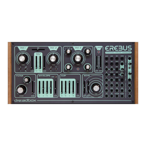
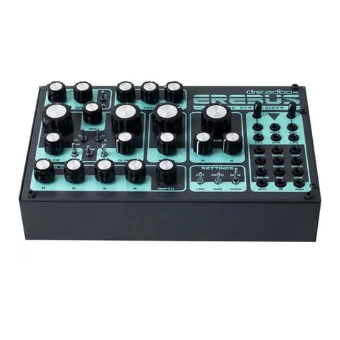
Dreadbox Erebus User manual

Dreadbox

Dreadbox Erebus User manual

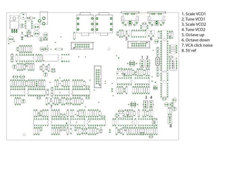
Dreadbox HADES User manual

Dreadbox

Dreadbox HADES User manual

Dreadbox HADES User manual

Dreadbox

Dreadbox HADES User manual

Dreadbox TYPHON User manual

Dreadbox

Dreadbox TYPHON User manual

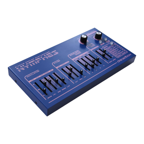
Dreadbox Nymphes User manual

Dreadbox

Dreadbox Nymphes User manual

Dreadbox HADES User manual

Dreadbox

Dreadbox HADES User manual

Dreadbox Erebus User manual

Dreadbox

Dreadbox Erebus User manual

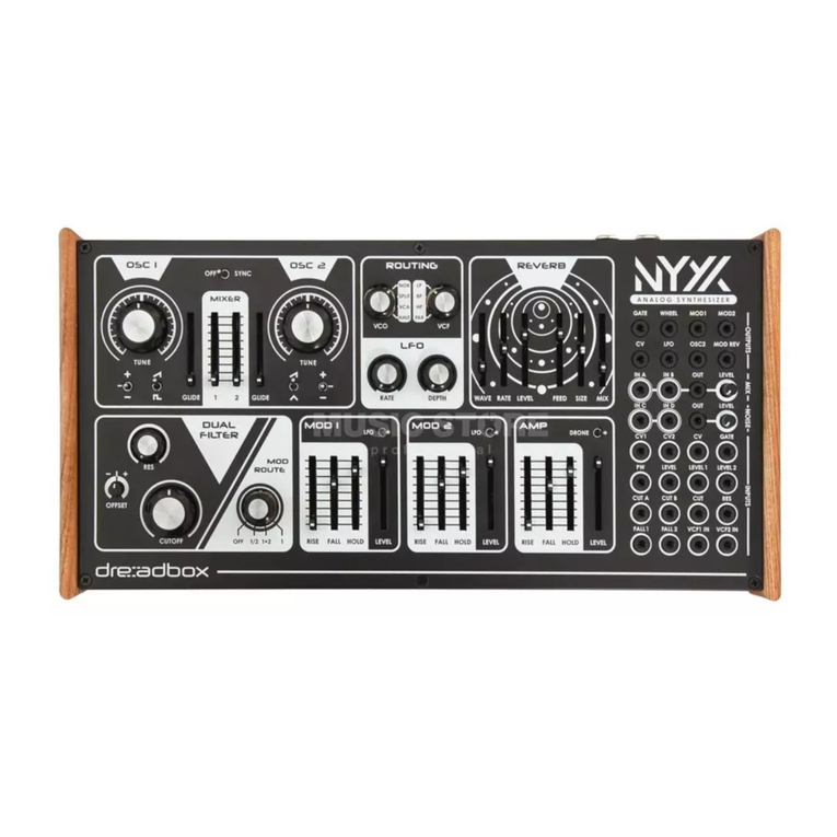
Dreadbox Nyx V2 User manual

Dreadbox

Dreadbox Nyx V2 User manual

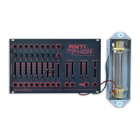
Dreadbox ANTIPHON User manual

Dreadbox

Dreadbox ANTIPHON User manual

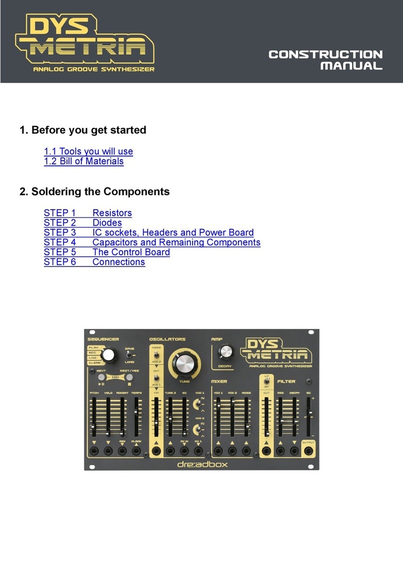
Dreadbox DYSMETRIA Instructions for use

Dreadbox

Dreadbox DYSMETRIA Instructions for use

Dreadbox Erebus User manual

Dreadbox

Dreadbox Erebus User manual

Dreadbox Erebus V3 User manual

Dreadbox

Dreadbox Erebus V3 User manual

Dreadbox Murmux Initiate User manual

Dreadbox

Dreadbox Murmux Initiate User manual

Dreadbox Nyx V2 User manual

Dreadbox

Dreadbox Nyx V2 User manual

Popular Synthesizer manuals by other brands

NEON CAPTAIN Radioator user manual

NEON CAPTAIN

NEON CAPTAIN Radioator user manual

Roland JD-800 owner's manual

Roland

Roland JD-800 owner's manual

Joranalogue Contour 1 user manual

Joranalogue

Joranalogue Contour 1 user manual

Full Bucket Music Mono/Fury manual

Full Bucket Music

Full Bucket Music Mono/Fury manual

IK Multimedia UNO Synth PRO X user manual

IK Multimedia

IK Multimedia UNO Synth PRO X user manual

Kawai MP7 Software update

Kawai

Kawai MP7 Software update

Roland Gaia SH-01 Quick guidebook

Roland

Roland Gaia SH-01 Quick guidebook

Behringer DEEPMIND 12 quick start guide

Behringer

Behringer DEEPMIND 12 quick start guide

Yamaha S90 ES owner's manual

Yamaha

Yamaha S90 ES owner's manual

Roland GR-30 manual

Roland

Roland GR-30 manual

Moog Minitmoog 300A Owner's service manual

Moog

Moog Minitmoog 300A Owner's service manual

Gotharman Gotharman's anAmoNo-box user manual

Gotharman

Gotharman Gotharman's anAmoNo-box user manual

QuStream HDFS-550 Technical manual

QuStream

QuStream HDFS-550 Technical manual

Yamaha V50 Authorized product manual

Yamaha

Yamaha V50 Authorized product manual

Akai AX80 Operator's manual

Akai

Akai AX80 Operator's manual

Roland GS-500 instructions

Roland

Roland GS-500 instructions

Octave Cat SRM Service manual

Octave

Octave Cat SRM Service manual

neutral labs ELMYRA 2 Build guide

neutral labs

neutral labs ELMYRA 2 Build guide

manuals.online logo
manuals.online logoBrands
  • About & Mission
  • Contact us
  • Privacy Policy
  • Terms and Conditions

Copyright 2025 Manuals.Online. All Rights Reserved.

CONSTRUCTION
MANUAL
In the box you will nd:
- 3 x PCB boards
- The Aluminum panel
- A plastic bag with parts
- The metal enclosure
- A ribbon cable
- A DIN5 to 3,5mm MIDI Adapter
The plastic bag contains:
- 10 small knobs
- 3 large knobs
- 4 rubber feet
- A 2mm hex driver
- 14xM3 brass bolts
- 6xM3 black bolts
- 8 metal spacers 10mm length M3
- 8 washers M3
- 13 pot washers
- 13 pot nuts M10
Additionally, you will need to have:
- A tuner
- A multimeter
- A 10mm HEX nut screwer
- A small straight screwdriver for trimming
- A larger straight screwdriver for the knobs
- A Philips PH1 screwdriver
- A USB adapter at least 1A of power
- A good USB cable
- A mini jack 3,5mm to 6,4mm
- A few patch cables 3,5mm
- A couple of crocks connectors
Step 1
Place the 2 bolts as shown in the picture, so that the spacers are facing on the components side.
Step 2
Place the 4 bolts as shown in the picture, so that the spacers are not facing on the components side.
Step 3
Connect the panel with the board. Place all nuts and washers as shown in the picture and then bolt
the 2 black bolts. While doing this do not apply too much force.
Step 4
Prepare the bottom PCB by attaching the holders for the power board.
Step 5
Connect the two boards. Be careful not to bend the headers while you attach them. Then bolt them in
place.
Step 6
Place the power board.
Step 7
Attach the knobs to the potentiometers. All knobs have a set screw to the side. Use the straight
screwdriver to rm them tightly as shown in the picture.
Step 7 - Tuning
This is the most challenging part of the build.
First thing you should do, is to prepare your
workbench. Make sure that your working area is all
cleaned up and we strongly suggest to use the foam
to support the module.
1. Connect a patch cable from the 1v/OCV output.
2. Use the crocks to connect the multimeter with the
minijack as shown. The red goes to the tip and the
black goes to the ground. Then turn the multimeter
on to the DC voltage measurement.
3. Connect the module to a USB power source.
IMPORTANT NOTE: To enter the calibration mode
you must ip the OMNI/CHAN switch 6 times in the
rst 10 seconds that the unit is powered.
4. After entering the calibration mode :
- Set A, D/R and S knobs (from the Envelope) to
about 50% travel.
- Set the LEG/OFF switch to the OFF position
- Flip the DR/R switch until the multimeter shows
about 0V.
- Now ip the DR/R switch again.
- The multimeter will show a measurement of about
3volts. Use the “A” knob to set it as close as possible
to 3 volts. The ideal voltage is 3.000mV (3V =
3000mV) but that is not always possible. You can
allow a 0,010 offset with no problems.
- Then ip the DR/R again. The multimeter will show
about 6 volts. This time use the D/R knob to set it to
6.000 volts.
- Then ip the DR/R switch one last time. The multi
meter will show about 9 volts. Use the S knob to set
it to 9,000.
IMPORTANT NOTE: After setting it up make sure not
to touch these knobs again while in calibration
mode, because the setting will be lost and you will
need to run the process again.