Dream-Flight alula TREK User manual


Designed to go wherever inspiration takes you...
Sometimes where we get to fly is as magical as the flying itself. The Alula-TREK is ready to make the journey
wherever the lift takes you. The world’s most popular bird-like RC flying wing is back and more refined than
ever. Whether you're hiking on a mountain ridge, riding the breeze on a dune at the beach, or searching for
thermals at the neighborhood park... the Alula-TREK is ready to go. This modular design is equally at home
secured on a backpack or stowed in an overhead bin. Be inspired: fly where you never considered.
Modern RC Glider Design
The Alula-TREK was developed from the ground up to provide pilots of all skill levels a unique RC soaring
experience with minimal building skills required. Getting into the air has never been easier with features like a
factory-installed skid plate, pre-installed canopy retention magnets, and pre-glued carbon spars and control
horns. Previously only available by separate purchase, the Alula-TREK now includes an integrated wing retention
system as a standard feature. The most refined Alula yet is ready to get out and glide, when you are.

“Alula”- Why the Name?
We love birds! A few years back we stumbled onto the word “alula” while looking for inspiration through a book
on bird anatomy. Officially pronounced “al-you-la” in the bird world, we like the sound of “ah-loo-la” when
referring to our glider.
Upon researching further, we learned that the “alula” on a bird wing (see figure below) is a set of feathers
attached to the bird’s equivalent of a thumb. These “thumb feathers” on a bird serve as a quasi leading edge
slotted flap that helps to delay the onset of a stall. It works by maintaining the airflow over the top of the wing
at high angles of attack. This serves the bird well during take-off, landing, and perching in difficult locations.
Simply put, we found the name fitting due to the low speed performance of this little glider and its bird-like
appearance. Given that many of us use our thumbs to control our RC aircraft, this little glider provides us with
some “thumb feathers” of our own.
al·u·la
New Latin origin, meaning a little wing.
The group of three to six small, rather stiff feathers
growing on the first digit, or thumb of a bird's wing.
An evolutionary adaptation which delays the onset of
stall by reinvigorating wing airflow.
A Red-tailed Hawk prepares for landing
with Alulae (pl.) in full effect.

Designer's Notes
"Originally, I wanted to design a glider with which I could join the Red-tailed Hawks in flight above my parents'
home in the Santa Barbara foothills. The design needed to be easily flung to soaring altitude above the oak-
studded hillside, and had to be able to negotiate the often light and inconsistent canyon updrafts. Over the
years, the Alula design has evolved into a glider that can be taken and flown just about anywhere, without much
hassle. The Alula's simplicity and low parts count inspires a sense of freedom, while it's organic form triggers the
same sentiment one often experiences while admiring a soaring bird in flight.
The Alula-TREK's wing mimics the gently forward-swept configuration used by the Red-tailed Hawk, and many
other soaring birds for that matter. This crucial design element is conducive to low speed circling flight which
helps the pilot navigate small, confined sources of lift by eliminating tip stalls and maximizing control surface
authority at very low airspeeds. This nature-inspired wing design also has the added benefit of lending itself to
the wingtip launch method, contributing to a straighter launch when coupled with the large vertical tail.
Overall, the sleek compact shape, low weight, forward-swept wing, and optimized airfoils and tail, all make for
a glider which launches easily to altitude and responds quickly to lift, allowing the pilot to "get on step" quickly
within a thermal. The minimalist flying wing configuration also makes for hassle-free flying since it is robust and
easy to repair on the spot." -Michael Richter, January 2015.
Michael Richter with an early hand-cut Alula prototype
in 2004. The Alula's low weight, easy launching, and
tight maneuverability allowed Michael to achieve his
dream of joining the Red-tailed Hawks in the light
updrafts above his parent's canyon-side home in Santa
Barbara, California.
3D CAD rendering shows the evolution of the Alula design that continues
in 2015 with the new Alula-TREK. This further refined design features the
easiest assembly and setup to date.


CAUTION! READ BEFORE PROCEEDING:
►The Alula-TREK RC glider is not a toy; a certain amount of experience and practice is required
to safely fly this model. We recommend consulting an experienced RC pilot before attempting to
fly this glider. With proper instruction, learning to fly RC gliders can be a safe and extremely
rewarding activity.
►ALWAYS fly model aircraft, such as the Alula-TREK, in open areas away from overhead
power/telephone lines, groups of people, trees, roads, buildings, and airports.
►BE CONSIDERATE AND RESPECTFUL! Always be considerate of passersby, spectators, and
other pilots by maintaining a safe distance between them and your aircraft during flight.
Choosing a designated safe landing zone is good practice and always give larger, heavier flying
models the right of way. Treat flying sites with the utmost of respect and care, as future access to
them is by no means guaranteed.
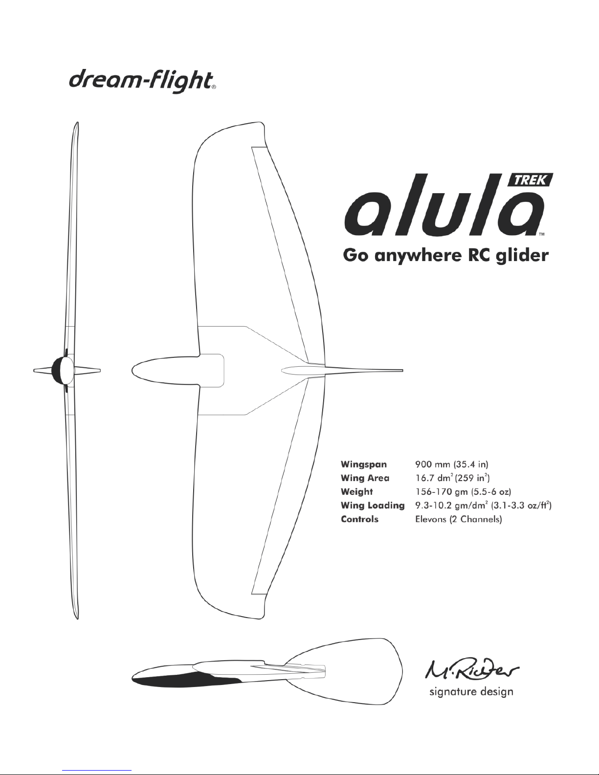
►The Alula-TREK must be assembled, balanced, and trimmed properly to ensure smooth,
efficient flight. Poor balance and trim WILL lead to poor flight characteristics. This is especially
true for small flying wings like the Alula-TREK that usually require a bit of fine-tuning to achieve
the best flight characteristics. Don’t be discouraged if it takes you a few flights to get it just right.
Additionally, make sure to observe proper control surface deflections that suit your skill level.
►The side-arm launch method places a certain amount of physical stress on one's body and
glider. Please proceed with caution when attempting this launch method.
►Do not store glider in areas of excessive heat, as this may cause foam parts to warp/deform,
thus adversely affecting the flight characteristics. Additionally, never place objects/weight on
glider during storage and transport unless foam parts are properly supported to prevent
warping.

TABLE OF CONTENTS
Pg. Topic
1 Kit Contents
2 Items Required for Completion (not included)
3 Radio Gear Setup
5 Fuselage Preparation
7 Wing and Tail Installation
11 Balancing the Alula-TREK
13 Control Surface Deflections
14 Ballast Option
15 Pre-Flight Check
16 Test Flights: Trimming for Straight and Level Flight
17 Side-Arm Launch Technique
19 Fine-Tuning Balance Position
21 “Urban Soaring” Technique
Background
Important guidelines to follow when flying the Alula-TREK
Slope Soaring
Flatland Soaring
To familiarize yourself with the assembly process, we recommend
reading over this manual before proceeding with final assembly.
When assembling your Alula-TREK, make sure to check
out the HOT TIPS found throughout this manual.

KIT CONTENTS
ITEM
DESCRIPTION
1
Fuselage and Canopy
2
L/R Wing Panels
3
Flight and Assembly Manual
4
Vertical Tail Fin
5
Small Hardware Bag Contents:
(2) Elevon pushrods
(2) Wing clamp screws
(2) Clevises with screws
Velcro for battery and receiver installation
Not shown: Logos, wing decals, and servo decals set
1.
Spare Parts
available at
dream-flight.com

ITEMS REQUIRED FOR COMPLETION (not included)
Radio Gear:
Programmable 6 channel radio system with Elevon Mixing and Dual Rates (see suggestion below)
Micro receiver, 4-6 gram weight (see chart below for receiver suggestion)
(2) Sub-micro servos (Part DFFA005 recommended, or purchase our Alula-TREK flight pack, Part DFFA008)
Receiver battery: 4.8V 300mAh 1/3AA NiMH (Part DFFA001)
Battery Extension Wire (Part DFFA013)
Tools and Extras:
Small Phillips screwdriver
Small wire or fingernail clippers for trimming servo arms
Sharp hobby knife or razor blade for relieving foam hinges
Small needle-nose pliers
Ruler or measuring tape (for setting control surface deflections)
Small weights for balancing and Ballast Option: Use our non-lead Steel Balance Weights (Part DFAA002)
Adhesives and Tape:
Blenderm Tape (Part 1525-0) for securing wing panels and making small repairs
20-25mm (1”) wide painter's masking tape –we like the blue or green stuff by 3M!
Optional:
Packing tape and strapping tape for airframe reinforcement and repair
Acrylic paints - add your personal style! Remember to clean foam with denatured alcohol first.
Suggested Transmitter and Receiver:
Transmitter
Receiver
Futaba
T6J, *T8J
*R2106GF
*We used the Futaba T8J 2.4GHz transmitter
and Futaba R2106GF receiver for our own
setup. The R2106GF receiver's extremely short
antenna makes installation a breeze! The T8J
transmitter features a special built-on antenna
for durability, and boasts easy to use, yet very
comprehensive, programming features.
2.

RADIO GEAR SETUP
►The following setup is based on the use of our 4.3g Digital servos (Part DFFA004). We have included the
exact measurements needed to recreate our setup if you choose another type of servo; however, don't skimp on
servos for your Alula-TREK! A good quality digital servo with excellent centering will ensure that your Alula-TREK
is a smooth, predictable flyer.
Gather items below:
Transmitter (battery fully charged)
Micro receiver
(2) Servos with servo arms and screws (Part
DFFA005)
Battery Extension Wire (Part DFFA013)
4.8V, 300mAh receiver battery (fully charged)
1. Locate servo arms with two holes on each arm.
Place tiny servo screws in a safe place.
2. Using small wire clippers, trim away one side of
each servo arm as shown.
3. Plug Battery Extension Wire into receiver
(observe proper polarity!). This extension wire
replaces a switch and makes it easier to turn on
the glider and charge the battery.
4. Turn on transmitter and plug battery into female
end of Battery Extension Wire to power up
receiver.
5. Activate transmitter's Elevon mixing function
(consult your radio manual for details). Elevon
mixing may be referred to as "Delta" mixing on
some transmitter models.
6. Connect servos to appropriate receiver channels.
Confirm system is bound and servos are
responding smoothly.
7. Ensure all Trims and Sub-Trims are set to zero,
and all End Points and/or Adjustable Throw
Volumes (ATV) are set to the default of 100%.
3.

8. Arrange servos on table and attach a servo arm to
each servo. IMPORTANT: Servo arms must be
installed in the orientations shown to ensure
proper control function.
9. Referring to graphic to the right, check for correct
servo rotation direction. If needed, reverse servo
directions using transmitter. If you cannot achieve
the correct rotations using servo reversing alone,
you may need to swap the servo plugs at the
receiver and return to Step 8 above.
10. If necessary, adjust sub-trims to ensure servo arms
are at 90 degrees as shown.
11. With a bit of masking tape, label each servo for
future reference during installation (i.e. Right, Left).
12. Re-install two tiny screws to secure each servo arm.
13. Power down receiver by unplugging battery from
Battery Extension Wire. Now turn off transmitter.
4.

FUSELAGE PREPARATION
Gather items below:
Fuselage with canopy
(2) Elevon servos
Receiver with Battery Extension Wire (Part DFFA013) attached
4.8V, 300mAh receiver battery
(2) Servo mounting decals (Clear, 37mm square)
Velcro strips
1. Remove canopy by gripping it near wing and
raising the right side as shown. This allows
canopy to "hinge" open lengthwise.
2. Insert servos into molded pockets and route wire
leads through provided cutouts and into receiver
compartment.
3. Apply provided servo mounting decals over each
servo as shown. Using a sharp hobby knife, trim
away the small area of decal covering the
Balance Locators beside the servo wire cutouts.
DO NOT remove the raised Balance Locator
lines, as these will be used for final balancing of
the model.
5.

4. Apply 50mm-long x 13mm-wide Velcro strips to battery and inside fuselage battery compartment. Note
that each large piece of Velcro is split down the middle to make the 13mm-wide strips. The Velcro allows
the battery to be adjusted fore and aft during final balancing. Use the remaining Velcro for mounting
receiver or a spare battery.
5. For now, mount battery in the most forward position.
6. Twist the servo wires together for a neater installation and then plug both elevon servo plugs into the proper
receiver channel ports (as determined in "Radio Gear Setup").
7. Install receiver as shown. You can use the extra Velcro or a bit of double-sided tape if you like.
8. Replace canopy and check it for proper fit. If necessary, tidy up your wiring so that it does not interfere
with fit of canopy.
6.

WING AND TAIL INSTALLATION
Gather items below:
Wing Panels (Right/Left)
Wingtip Reinforcement Decals (apply to launching wingtip only)
Completed Fuselage (with servos, battery, and receiver installed)
(2) Elevon pushrods
(2) Adjustable clevises with black clamping screws
(2) Wing Clamp Screws (7mm-long x 2mm dia.)
Tail Fin
1. Enhance control response and reduce servo load by making 20mm-long incisions along foam hinges using a
sharp hobby knife. Alternate, leaving approximately 15mm of intact hinge material between incisions
(imagine a dashed line cut pattern as shown below). Make sure to leave 20mm of intact hinge material also
at each end of control surface. Flex foam ailerons 45 degrees in each direction a few times to loosen hinge
action.
2. Apply provided reinforcement decals to desired
launching wingtip. If you are right-handed, apply
decals to left wing tip and vice versa for left-handers.
Apply decals to both top and bottom of desired
wingtip, making sure to note proper orientation as
shown to the right.
7.

3. Prepare two clevises by folding sides together, creating a slot where pushrod will be clamped. With clevis
folded, install small clamping screw through each clevis. Do not tighten screw at this point.
4. Slide a clevis onto end of each elevon pushrod. You may have to loosen clamping screw slightly to allow
clevis to slide onto pushrod end.
5. While holding fuselage in hand,
slide one wing panel at a time onto
carbon-fiber joiner, with leading
edge of wing angled downward as
shown. Once wing panel contacts
fuselage, rotate wing panel
allowing magnets to snap into
contact.
8.

6. Locate and install two wing clamp screws into wing clamps as shown below. Firmly tighten the wing clamp
screw in each panel. The wing clamp screws can be loosened at any point to remove wing panels for travel
and storage.
7. IMPORTANT: For added security during
aggressive side-arm launches, please
wrap a strip of tape (Blenderm 1525-0)
around each wing joint at the leading
edge as shown. It is possible for the
wing clamp to loosen after a hard
landing or a few "aggressive" launches.
This can result in the wing separating
from the fuselage during a sidearm
launch. Between flights, make sure to
inspect your wing joints for any signs of
loosening or separation.
9.

8. Insert wire "U-Bend" side of
each pushrod into outermost
(second) hole of servo arms.
9. Ensure that both clevises slide
freely on each pushrod for the
next adjustments. Loosen clevis
screw if necessary.
10. Turn on transmitter and plug
battery into the Extension Wire
to power up servos. Double
check that your servo arms are
centered.
11. Connect clevises to elevon
control horns at outermost hole
as shown.
12. Align elevons with fuselage and
wingtips as shown to the right.
Adjust clevis as necessary and
tighten clevis screws with
elevons in their correct neutral
position. Do not over-tighten
clevis screws; when properly
tightened, tip of screw should
protrude slightly from side of
clevis. Check by hand to make
sure clevis is now locked onto
pushrod. It is possible to add a
drop of instant glue to rear of
clevis (pushrod side) for added
security; however, do not get
any glue near the clevis pin and
control horn.
13. Slide Tail Fin onto glider from
rear until it locks in position. The
tail is held in place by a friction
fit. If it loosens over time, use a
piece of tape to secure it.
10.

BALANCING THE ALULA-TREK
►IMPORTANT: The Alula-TREK must be assembled, balanced, and trimmed properly to ensure smooth, efficient
flight. Poor balance and trim WILL lead to poor flight characteristics. This is especially true for small flying wings
like the Alula-TREK which almost always require a bit of fine-tuning to achieve best flight characteristics. Don’t be
discouraged if it takes you a few flights to get the balance and trim just right.
Gather items below:
Fully assembled Alula-TREK
Small balance weights (not always necessary). You may only need small paperclips or coins to get the balance
correct. If you need more weight, try our non-lead Steel Balance Weights (Part DFAA002).
1) Ensure all components of glider are attached and installed. Replace canopy if not already installed.
2) Find the Balance Locators on underside of wing, just ahead of servos. This Center of Gravity (CG) position
provides the Alula-TREK with a very neutral flight and launch behavior. It may be a bit too neutral for some
pilots who appreciate a little more hands-off stability, but it is a good place to start nonetheless. If the
Balance Locators are partially covered with the servo mounting decals, expose them by trimming away a
small amount of the plastic decal material using a sharp hobby knife (this will allow you to better feel the
balance locators with your fingertips).
11.

3) Center your fingertips on the Locators to balance the glider and see how it reacts. If the nose drops quickly,
move battery rearward until glider balances level on fingertips. If the tail drops quickly, slide battery
forward if possible, or add a small amount of balance weight in the provided recesses alongside battery
(you may only need a small paperclip or two). The Alula-TREK's short length makes balancing a bit tricky,
so take your time and make sure glider balances level on your fingertips for at least a moment or two
before it starts to fall out of balance. Proper balance is crucial! If you don't trust your fingertips, use the Hot
Tip below for a more precise way to balance your Alula-TREK.
►HOT TIP: If you don't trust your fingertips to
balance the glider, make a simple balancing jig
out of a block of wood and two dowels or pencils.
The tips of the dowels should be wedge-shaped to
provide a fairly sharp balancing tip. Space the
dowels 65 mm apart, so the tips align with the
middle of the Balance Locators.
12.

CONTROL SURFACE DEFLECTIONS
The control surface deflections in the table below provide the Alula-TREK with active response to control inputs.
You can set separate Low and High rates using the "Dual Rate" menu and toggle switches on your
programmable transmitter. Before proceeding, make sure all End Points and/or Adjustable Throw Volumes (ATV)
are set to the default of 100%. IMPORTANT:Elevon deflections can be adjusted to suit one's own flying style,
but make sure to pay particular attention to your elevator deflections (a little goes a long way for a flying
wing!). Too much elevator deflection will result in inefficient over-controlling, stalling, and poor flight behavior.
►HOT TIP: As shown below, apply a piece of painter's tape to the tail, just behind elevon control surface for setting
deflections. Mark desired deflections on tape and adjust transmitter Dual Rates until proper deflections are achieved.
* Provides the approximate Dual Rate (D/R) settings in percent. These settings will get you
close to the listed deflections, but make sure to confirm through physical measurement.
LOW RATES
HIGH RATES
Elevator
(Pitch Control)
3mm UP
3mm DOWN
*D/R: 20%
5mm UP
5mm DOWN
*D/R: 35%
Aileron
(Roll Control)
10mm UP
10mm DOWN
*D/R: 75%
13mm UP
13mm DOWN
*D/R: 100%
13.
Table of contents
Other Dream-Flight Aircraft manuals
Popular Aircraft manuals by other brands

Hawker Beechcraft
Hawker Beechcraft Hawker 850XP Flight manual

BOMBARDIER
BOMBARDIER Challenger 300 Flight crew operating manual

EVEKTOR-AEROTECHNIK
EVEKTOR-AEROTECHNIK SPORTSTAR FLIGHT TRAINING SUPPLEMENT

Fresh Breeze
Fresh Breeze X-Light F 23 Flight manual

Swing
Swing HYBRID SPORT manual

Swing
Swing Twin RS instruction manual