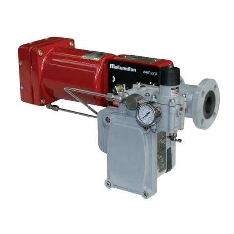
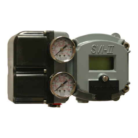
Dresser MASONEILAN ValVue User manual

MASONEILAN ValVue
®
SOFTWARE INTERFACE TO SVI
®
INSTRUCTION
MANUAL
EW1000
04/99

Masoneilan is a registered trademark of Dresser Industries Inc., A Halliburton Company
SVI is a registered trademark of Dresser Industries, Inc.
ValVue is a trademark of Dresser Industries, Inc.
HART is a registered trademark of the Hart Foundation
Pentium is a trademark of Intel Corporation
Windows is a trademark of Microsoft Corporation
Copyright 1999 by Dresser Equipment Group, Inc.
All rights reserved

I
Table of Contents
CHAPTER 1: OVERVIEW . . . . . . . . . . . . . . . . . . . . . . . . . . . . . . . . . . . . . . . . .1
Scope of Manual . . . . . . . . . . . . . . . . . . . . . . . . . . . . . . . . . . . . . . . . . . . . . . . . . . . . . . . . . .1
SVI and ValVue . . . . . . . . . . . . . . . . . . . . . . . . . . . . . . . . . . . . . . . . . . . . . . . . . . . . . . . .1
ValVue Features and Functions . . . . . . . . . . . . . . . . . . . . . . . . . . . . . . . . . . . . . . . . . . . .1
SVI Features and Functions . . . . . . . . . . . . . . . . . . . . . . . . . . . . . . . . . . . . . . . . . . . . . .2
CHAPTER 2: VALVUE INSTALLATION AND COMPUTER REQUIREMENTS . .3
Hardware and Software Requirements . . . . . . . . . . . . . . . . . . . . . . . . . . . . . . . . . . . . . . . . . .3
Installing ValVue . . . . . . . . . . . . . . . . . . . . . . . . . . . . . . . . . . . . . . . . . . . . . . . . . . . . . . . . . .3
HART Compliance . . . . . . . . . . . . . . . . . . . . . . . . . . . . . . . . . . . . . . . . . . . . . . . . . . . . . . . . .4
Failure to Communicate . . . . . . . . . . . . . . . . . . . . . . . . . . . . . . . . . . . . . . . . . . . . . . . . .4
CHAPTER 3: SVI MODES . . . . . . . . . . . . . . . . . . . . . . . . . . . . . . . . . . . . . . . . .5
Modes . . . . . . . . . . . . . . . . . . . . . . . . . . . . . . . . . . . . . . . . . . . . . . . . . . . . . . . . . . . . . . . . . .5
CHAPTER 4: SYSTEM ADMIN., PASSWORDS, AND PRIVILEGE LEVELS . . .6
Start the Administration Program . . . . . . . . . . . . . . . . . . . . . . . . . . . . . . . . . . . . . . . . . . . . . .6
Privilege Level . . . . . . . . . . . . . . . . . . . . . . . . . . . . . . . . . . . . . . . . . . . . . . . . . . . . . . . . . . . .7
Adding and Changing a User Account . . . . . . . . . . . . . . . . . . . . . . . . . . . . . . . . . . . . . . . . . .8
Deleting a User Account . . . . . . . . . . . . . . . . . . . . . . . . . . . . . . . . . . . . . . . . . . . . . . . . . . . .8
CHAPTER 5: STARTING VALVUE . . . . . . . . . . . . . . . . . . . . . . . . . . . . . . . . . . .9
Logon . . . . . . . . . . . . . . . . . . . . . . . . . . . . . . . . . . . . . . . . . . . . . . . . . . . . . . . . . . . . . . . . . .9
Starting ValVue for the First Time . . . . . . . . . . . . . . . . . . . . . . . . . . . . . . . . . . . . . . . . . .9
Starting ValVue with a Password after Registration . . . . . . . . . . . . . . . . . . . . . . . . . . . .11
Starting ValVue with a Valid Password . . . . . . . . . . . . . . . . . . . . . . . . . . . . . . . . . . . . . .11
Device Selection . . . . . . . . . . . . . . . . . . . . . . . . . . . . . . . . . . . . . . . . . . . . . . . . . . . . . .11
Hart Options . . . . . . . . . . . . . . . . . . . . . . . . . . . . . . . . . . . . . . . . . . . . . . . . . . . . . . . . . . . .13
Offline SVI Mode . . . . . . . . . . . . . . . . . . . . . . . . . . . . . . . . . . . . . . . . . . . . . . . . . . . . . . . . .14
CHAPTER 6: QUICK TOUR OF VALVUE WINDOWS FOR SVI . . . . . . . . . . . .16
Normal Operating Mode . . . . . . . . . . . . . . . . . . . . . . . . . . . . . . . . . . . . . . . . . . . . . . . .16
Process Trend Data . . . . . . . . . . . . . . . . . . . . . . . . . . . . . . . . . . . . . . . . . . . . . . . . . . . .17
Manual Mode . . . . . . . . . . . . . . . . . . . . . . . . . . . . . . . . . . . . . . . . . . . . . . . . . . . . . . . .18
Configuration Mode . . . . . . . . . . . . . . . . . . . . . . . . . . . . . . . . . . . . . . . . . . . . . . . . . . . .19
Process Controller . . . . . . . . . . . . . . . . . . . . . . . . . . . . . . . . . . . . . . . . . . . . . . . . . . . . .21
Calibration . . . . . . . . . . . . . . . . . . . . . . . . . . . . . . . . . . . . . . . . . . . . . . . . . . . . . . . . . . .21
Range Values . . . . . . . . . . . . . . . . . . . . . . . . . . . . . . . . . . . . . . . . . . . . . . . . . . . . . . . .22
Position Controller Parameters . . . . . . . . . . . . . . . . . . . . . . . . . . . . . . . . . . . . . . . . . . .22
Signal Calibration . . . . . . . . . . . . . . . . . . . . . . . . . . . . . . . . . . . . . . . . . . . . . . . . . . . . .23
Diagnostic Data . . . . . . . . . . . . . . . . . . . . . . . . . . . . . . . . . . . . . . . . . . . . . . . . . . . . . . .24
Actuator Signature . . . . . . . . . . . . . . . . . . . . . . . . . . . . . . . . . . . . . . . . . . . . . . . . . . . . .25
Extended Actuator Signature . . . . . . . . . . . . . . . . . . . . . . . . . . . . . . . . . . . . . . . . . . . .26
Positioner Signature . . . . . . . . . . . . . . . . . . . . . . . . . . . . . . . . . . . . . . . . . . . . . . . . . . .27

II
Controller . . . . . . . . . . . . . . . . . . . . . . . . . . . . . . . . . . . . . . . . . . . . . . . . . . . . . . . . . . .27
Controller Monitor . . . . . . . . . . . . . . . . . . . . . . . . . . . . . . . . . . . . . . . . . . . . . . . . . . . . .28
Controller Parameters . . . . . . . . . . . . . . . . . . . . . . . . . . . . . . . . . . . . . . . . . . . . . . . . . .29
Fail Safe Mode . . . . . . . . . . . . . . . . . . . . . . . . . . . . . . . . . . . . . . . . . . . . . . . . . . . . . . .30
CHAPTER 7: NORMAL OPERATING MODE . . . . . . . . . . . . . . . . . . . . . . . . . .31
Valve Monitoring . . . . . . . . . . . . . . . . . . . . . . . . . . . . . . . . . . . . . . . . . . . . . . . . . . . . . . . . .31
Reading Configuration and Calibration Data . . . . . . . . . . . . . . . . . . . . . . . . . . . . . . . . . . . . .32
Process Trends . . . . . . . . . . . . . . . . . . . . . . . . . . . . . . . . . . . . . . . . . . . . . . . . . . . . . . . . . .33
Viewing Valve Signatures . . . . . . . . . . . . . . . . . . . . . . . . . . . . . . . . . . . . . . . . . . . . . . . . . . .34
Reports . . . . . . . . . . . . . . . . . . . . . . . . . . . . . . . . . . . . . . . . . . . . . . . . . . . . . . . . . . . . . . . .35
Check SVI . . . . . . . . . . . . . . . . . . . . . . . . . . . . . . . . . . . . . . . . . . . . . . . . . . . . . . . . . . . . . .36
Saving and Restoring SVI Data . . . . . . . . . . . . . . . . . . . . . . . . . . . . . . . . . . . . . . . . . . . . . .37
Going to Other Modes . . . . . . . . . . . . . . . . . . . . . . . . . . . . . . . . . . . . . . . . . . . . . . . . . . . . .37
Going to Manual Mode . . . . . . . . . . . . . . . . . . . . . . . . . . . . . . . . . . . . . . . . . . . . . . . . .37
Exit to Device List Window . . . . . . . . . . . . . . . . . . . . . . . . . . . . . . . . . . . . . . . . . . . . . .37
CHAPTER 8: MANUAL OPERATING MODE . . . . . . . . . . . . . . . . . . . . . . . . .38
Valve Monitoring . . . . . . . . . . . . . . . . . . . . . . . . . . . . . . . . . . . . . . . . . . . . . . . . . . . . . . . . .38
Valve Manual Control . . . . . . . . . . . . . . . . . . . . . . . . . . . . . . . . . . . . . . . . . . . . . . . . . . . . . .39
Reading Configuration and Calibration Data . . . . . . . . . . . . . . . . . . . . . . . . . . . . . . . . . . . . .39
Reports . . . . . . . . . . . . . . . . . . . . . . . . . . . . . . . . . . . . . . . . . . . . . . . . . . . . . . . . . . . . . . . .40
Check SVI . . . . . . . . . . . . . . . . . . . . . . . . . . . . . . . . . . . . . . . . . . . . . . . . . . . . . . . . . . . . . .40
Saving and Restoring SVI Data . . . . . . . . . . . . . . . . . . . . . . . . . . . . . . . . . . . . . . . . . . . . . .40
Going to Other Modes . . . . . . . . . . . . . . . . . . . . . . . . . . . . . . . . . . . . . . . . . . . . . . . . . . . . .40
Going to Normal Operating Mode . . . . . . . . . . . . . . . . . . . . . . . . . . . . . . . . . . . . . . . . .40
Exit to Device List Window . . . . . . . . . . . . . . . . . . . . . . . . . . . . . . . . . . . . . . . . . . . . . .40
Going to Configure, Calibrate or Diagnostics Mode . . . . . . . . . . . . . . . . . . . . . . . . . . . .40
CHAPTER 9: CONFIGURATION MODE . . . . . . . . . . . . . . . . . . . . . . . . . . . . .41
Tag Page . . . . . . . . . . . . . . . . . . . . . . . . . . . . . . . . . . . . . . . . . . . . . . . . . . . . . . . . . . . . . . .42
Options Page . . . . . . . . . . . . . . . . . . . . . . . . . . . . . . . . . . . . . . . . . . . . . . . . . . . . . . . . . . .43
Custom Linearization . . . . . . . . . . . . . . . . . . . . . . . . . . . . . . . . . . . . . . . . . . . . . . . . . . .45
Local Button Lock . . . . . . . . . . . . . . . . . . . . . . . . . . . . . . . . . . . . . . . . . . . . . . . . . . . . .46
Bumpless Transfer . . . . . . . . . . . . . . . . . . . . . . . . . . . . . . . . . . . . . . . . . . . . . . . . . . . .46
Tight Shutoff and Position Limits . . . . . . . . . . . . . . . . . . . . . . . . . . . . . . . . . . . . . . . . . .47
Pressure Unit and Display Language . . . . . . . . . . . . . . . . . . . . . . . . . . . . . . . . . . . . . . .47
Setup Page . . . . . . . . . . . . . . . . . . . . . . . . . . . . . . . . . . . . . . . . . . . . . . . . . . . . . . . . . . . . .48
Positioner Error . . . . . . . . . . . . . . . . . . . . . . . . . . . . . . . . . . . . . . . . . . . . . . . . . . . . . . . . . .50
Controller Page . . . . . . . . . . . . . . . . . . . . . . . . . . . . . . . . . . . . . . . . . . . . . . . . . . . . . . . . . .50
CHAPTER 10: CALIBRATION MODE . . . . . . . . . . . . . . . . . . . . . . . . . . . . . . .51
Range Page . . . . . . . . . . . . . . . . . . . . . . . . . . . . . . . . . . . . . . . . . . . . . . . . . . . . . . . . . . . .52
Tuning Page . . . . . . . . . . . . . . . . . . . . . . . . . . . . . . . . . . . . . . . . . . . . . . . . . . . . . . . . . . . .54
Tune Positioner . . . . . . . . . . . . . . . . . . . . . . . . . . . . . . . . . . . . . . . . . . . . . . . . . . . . . . .54
Parameter Descriptions . . . . . . . . . . . . . . . . . . . . . . . . . . . . . . . . . . . . . . . . . . . . . . . . .56
Auto Tune Error Codes . . . . . . . . . . . . . . . . . . . . . . . . . . . . . . . . . . . . . . . . . . . . . . . . .57
Bias Adjustment . . . . . . . . . . . . . . . . . . . . . . . . . . . . . . . . . . . . . . . . . . . . . . . . . . . . . .57
Signal Calibration Page . . . . . . . . . . . . . . . . . . . . . . . . . . . . . . . . . . . . . . . . . . . . . . . . . . . .58

III
CHAPTER 11: DIAGNOSTIC MODE . . . . . . . . . . . . . . . . . . . . . . . . . . . . . . . .60
Introduction . . . . . . . . . . . . . . . . . . . . . . . . . . . . . . . . . . . . . . . . . . . . . . . . . . . . . . . . . . . . .60
Continuous Diagnostics . . . . . . . . . . . . . . . . . . . . . . . . . . . . . . . . . . . . . . . . . . . . . . . . .61
Standard Valve Diagnostic Test . . . . . . . . . . . . . . . . . . . . . . . . . . . . . . . . . . . . . . . . . . .62
Extended Actuator Signature . . . . . . . . . . . . . . . . . . . . . . . . . . . . . . . . . . . . . . . . . . . .64
Step Response Test . . . . . . . . . . . . . . . . . . . . . . . . . . . . . . . . . . . . . . . . . . . . . . . . . . .66
Positioner Signature . . . . . . . . . . . . . . . . . . . . . . . . . . . . . . . . . . . . . . . . . . . . . . . . . . .67
Saving and Retrieving Signatures . . . . . . . . . . . . . . . . . . . . . . . . . . . . . . . . . . . . . . . . . . . .68
Saving Signatures . . . . . . . . . . . . . . . . . . . . . . . . . . . . . . . . . . . . . . . . . . . . . . . . . . . . .68
Retrieving Signatures . . . . . . . . . . . . . . . . . . . . . . . . . . . . . . . . . . . . . . . . . . . . . . . . . .69
Exporting Signatures to Spreadsheets . . . . . . . . . . . . . . . . . . . . . . . . . . . . . . . . . . . . . .69
CHAPTER 12: FAILSAFE MODE . . . . . . . . . . . . . . . . . . . . . . . . . . . . . . . . . . .70
Fault Message . . . . . . . . . . . . . . . . . . . . . . . . . . . . . . . . . . . . . . . . . . . . . . . . . . . . . . . . . . .70
Exiting Failsafe Mode . . . . . . . . . . . . . . . . . . . . . . . . . . . . . . . . . . . . . . . . . . . . . . . . . . . . .71
CHAPTER 13: SVI MESSAGE RESPONSES . . . . . . . . . . . . . . . . . . . . . . . . .72
The HART commands are defined in three groups: . . . . . . . . . . . . . . . . . . . . . . . . . . . .73
Masoneilan Extended Commands include: . . . . . . . . . . . . . . . . . . . . . . . . . . . . . . . . . . .74
CHAPTER 14: SVI REPORTS . . . . . . . . . . . . . . . . . . . . . . . . . . . . . . . . . . . . .77
Report Format Files . . . . . . . . . . . . . . . . . . . . . . . . . . . . . . . . . . . . . . . . . . . . . . . . . . . . . . .77
Creating Reports . . . . . . . . . . . . . . . . . . . . . . . . . . . . . . . . . . . . . . . . . . . . . . . . . . . . . . . . .78
CHAPTER 15: CONTROLLER CONFIGURATION . . . . . . . . . . . . . . . . . . . . . .85
Turning Process Controller On . . . . . . . . . . . . . . . . . . . . . . . . . . . . . . . . . . . . . . . . . . . . . . .85
Controller Configuration in Controller Page . . . . . . . . . . . . . . . . . . . . . . . . . . . . . . . . . . . . .86
CHAPTER 16: CONTROLLER CALIBRATION . . . . . . . . . . . . . . . . . . . . . . . .88
Range Page . . . . . . . . . . . . . . . . . . . . . . . . . . . . . . . . . . . . . . . . . . . . . . . . . . . . . . . . . . . .89
Signal Calibration Page . . . . . . . . . . . . . . . . . . . . . . . . . . . . . . . . . . . . . . . . . . . . . . . . . . . .90
CHAPTER 17: CONTROLLER VIEW . . . . . . . . . . . . . . . . . . . . . . . . . . . . . . . .92
Controller Monitor . . . . . . . . . . . . . . . . . . . . . . . . . . . . . . . . . . . . . . . . . . . . . . . . . . . . . . . .92
Display of Process Controller . . . . . . . . . . . . . . . . . . . . . . . . . . . . . . . . . . . . . . . . . . . . .92
Alarm Status . . . . . . . . . . . . . . . . . . . . . . . . . . . . . . . . . . . . . . . . . . . . . . . . . . . . . . . . .94
Changes of Setpoint and Output of Process Controller . . . . . . . . . . . . . . . . . . . . . . . . . .94
Controller Fault Messages . . . . . . . . . . . . . . . . . . . . . . . . . . . . . . . . . . . . . . . . . . . . . . . . . .95
Mode Transfer of Process Controller . . . . . . . . . . . . . . . . . . . . . . . . . . . . . . . . . . . . . . . . . .95
Process Trends . . . . . . . . . . . . . . . . . . . . . . . . . . . . . . . . . . . . . . . . . . . . . . . . . . . . . . . . . .97
Controller Parameters . . . . . . . . . . . . . . . . . . . . . . . . . . . . . . . . . . . . . . . . . . . . . . . . . . . . .98
Controller Parameter Descriptions . . . . . . . . . . . . . . . . . . . . . . . . . . . . . . . . . . . . . . . . .99
Going to Other ValVue Windows . . . . . . . . . . . . . . . . . . . . . . . . . . . . . . . . . . . . . . . . . . . .100
Going to Normal or Manual Mode . . . . . . . . . . . . . . . . . . . . . . . . . . . . . . . . . . . . . . . .100
Exit to Device List Window . . . . . . . . . . . . . . . . . . . . . . . . . . . . . . . . . . . . . . . . . . . . .100
Simulation . . . . . . . . . . . . . . . . . . . . . . . . . . . . . . . . . . . . . . . . . . . . . . . . . . . . . . . . . . . . .100

IV
CHAPTER 18: MULTIPLEXER SETUP AND OPERATION . . . . . . . . . . . . . . .101
Introduction . . . . . . . . . . . . . . . . . . . . . . . . . . . . . . . . . . . . . . . . . . . . . . . . . . . . . . . . . . . .101
ValVue Multiplexer Options . . . . . . . . . . . . . . . . . . . . . . . . . . . . . . . . . . . . . . . . . . . . . . . .101
Options Window Setup . . . . . . . . . . . . . . . . . . . . . . . . . . . . . . . . . . . . . . . . . . . . . . . .101
Multiplexer Setup . . . . . . . . . . . . . . . . . . . . . . . . . . . . . . . . . . . . . . . . . . . . . . . . . . . . .103
Multiplexer Operation . . . . . . . . . . . . . . . . . . . . . . . . . . . . . . . . . . . . . . . . . . . . . . . . . . . . .104

V
FIGURES
Figure 1. ValVue System Administration . . . . . . . . . . . . . . . . . . . . . . . . . . . . . . . . . . .7
Figure 2. User Add/Change Window . . . . . . . . . . . . . . . . . . . . . . . . . . . . . . . . . . . . . .8
Figure 3. ValVue Registration Window . . . . . . . . . . . . . . . . . . . . . . . . . . . . . . . . . . . . .9
Figure 6. Device Selection Window . . . . . . . . . . . . . . . . . . . . . . . . . . . . . . . . . . . . . .10
Figure 5. Logon Window . . . . . . . . . . . . . . . . . . . . . . . . . . . . . . . . . . . . . . . . . . . . . . .10
Figure 4. Svi Windows Application Window . . . . . . . . . . . . . . . . . . . . . . . . . . . . . . . . .10
Figure 7. Burst Mode Control . . . . . . . . . . . . . . . . . . . . . . . . . . . . . . . . . . . . . . . . . . .12
Figure 8. Options Window . . . . . . . . . . . . . . . . . . . . . . . . . . . . . . . . . . . . . . . . . . . . .13
Figure 9. Open Dump File Window . . . . . . . . . . . . . . . . . . . . . . . . . . . . . . . . . . . . . .14
Figure 10. Normal Operating Mode - Offline Window . . . . . . . . . . . . . . . . . . . . . . . . . .15
Figure 11. Normal Operating Mode - Online Window . . . . . . . . . . . . . . . . . . . . . . . . . .16
Figure 12. Trend Data Window . . . . . . . . . . . . . . . . . . . . . . . . . . . . . . . . . . . . . . . . . . .17
Figure 13. Manual Mode Window . . . . . . . . . . . . . . . . . . . . . . . . . . . . . . . . . . . . . . . . .18
Figure 15. SVI Configuration Options Window . . . . . . . . . . . . . . . . . . . . . . . . . . . . . . .19
Figure 14. SVI Configuration Tag Page Window . . . . . . . . . . . . . . . . . . . . . . . . . . . . . .19
Figure 16. SVI Configuration Setup Window . . . . . . . . . . . . . . . . . . . . . . . . . . . . . . . . .20
Figure 17. SVI Configuration Controller Window . . . . . . . . . . . . . . . . . . . . . . . . . . . . . .21
Figure 19. SVI Calibration Tuning Window . . . . . . . . . . . . . . . . . . . . . . . . . . . . . . . . . .22
Figure 18. SVI Calibration Range Window . . . . . . . . . . . . . . . . . . . . . . . . . . . . . . . . . .22
Figure 20. SVI Signal Calibration Window . . . . . . . . . . . . . . . . . . . . . . . . . . . . . . . . . . .23
Figure 21. Diagnostics Window . . . . . . . . . . . . . . . . . . . . . . . . . . . . . . . . . . . . . . . . . .24
Figure 22. Valve Signature Window . . . . . . . . . . . . . . . . . . . . . . . . . . . . . . . . . . . . . . .25
Figure 23. Extended Actuator Signature . . . . . . . . . . . . . . . . . . . . . . . . . . . . . . . . . . . .26
Figure 24. Typical Positioner Signature . . . . . . . . . . . . . . . . . . . . . . . . . . . . . . . . . . . . .27
Figure 25. Controller Monitor Window . . . . . . . . . . . . . . . . . . . . . . . . . . . . . . . . . . . . . .28
Figure 26. Controller Parameters Window . . . . . . . . . . . . . . . . . . . . . . . . . . . . . . . . . .29
Figure 27. Fail Safe Mode Window . . . . . . . . . . . . . . . . . . . . . . . . . . . . . . . . . . . . . . . .30
Figure 28. Normal Operating Mode Window . . . . . . . . . . . . . . . . . . . . . . . . . . . . . . . . .31
Figure 29. Trend Data Window . . . . . . . . . . . . . . . . . . . . . . . . . . . . . . . . . . . . . . . . . . .33
Figure 30. Valve Signature Window . . . . . . . . . . . . . . . . . . . . . . . . . . . . . . . . . . . . . . .34
Figure 31. Report File Selection Window . . . . . . . . . . . . . . . . . . . . . . . . . . . . . . . . . . .35
Figure 32. SVI Monitor Window . . . . . . . . . . . . . . . . . . . . . . . . . . . . . . . . . . . . . . . . . .36
Figure 33. Manual Mode Window . . . . . . . . . . . . . . . . . . . . . . . . . . . . . . . . . . . . . . . . .38
Figure 34. SVI Configuration - Tag Window . . . . . . . . . . . . . . . . . . . . . . . . . . . . . . . . .42
Figure 35. SVI Configuration - Options Window . . . . . . . . . . . . . . . . . . . . . . . . . . . . . .43
Figure 36. Custom Characterization Window . . . . . . . . . . . . . . . . . . . . . . . . . . . . . . . .44
Figure 37. Custom Linearization Window . . . . . . . . . . . . . . . . . . . . . . . . . . . . . . . . . . .45
Figure 38. SVI Configuration - Setup Window . . . . . . . . . . . . . . . . . . . . . . . . . . . . . . . .48
Figure 39. SVI Calibration Range Window . . . . . . . . . . . . . . . . . . . . . . . . . . . . . . . . . .52
Figure 40. SVI Calibration - Tuning Window . . . . . . . . . . . . . . . . . . . . . . . . . . . . . . . . .54
Figure 41. Diagnostic Graph - Typical Step Response . . . . . . . . . . . . . . . . . . . . . . . . .55
Figure 42. SVI Calibration - Signal Calibration Window . . . . . . . . . . . . . . . . . . . . . . . . .58
Figure 43. Diagnostics Window . . . . . . . . . . . . . . . . . . . . . . . . . . . . . . . . . . . . . . . . . .62
Figure 44. Valve Signature Window . . . . . . . . . . . . . . . . . . . . . . . . . . . . . . . . . . . . . . .63
Figure 45. Diagnostic Graph - Extended Actuator Signature . . . . . . . . . . . . . . . . . . . . .65
Figure 46. Diagnostic Graph - Step Response Test . . . . . . . . . . . . . . . . . . . . . . . . . . . .66
Figure 47. Diagnostic Graph - Positioner Signature . . . . . . . . . . . . . . . . . . . . . . . . . . . .67
Figure 48. Saving Signatures Window . . . . . . . . . . . . . . . . . . . . . . . . . . . . . . . . . . . . .68
Figure 49. Load Diagnostics Window . . . . . . . . . . . . . . . . . . . . . . . . . . . . . . . . . . . . . .69
Figure 50. Fail Safe Mode Window . . . . . . . . . . . . . . . . . . . . . . . . . . . . . . . . . . . . . . . .70
Figure 51. Manual Mode Window . . . . . . . . . . . . . . . . . . . . . . . . . . . . . . . . . . . . . . . . .72

VI
Figure 52. Result of HART Command #141 Red Raw Data to SVI Window . . . . . . . . . .73
Figure 53. Report Format File Selection Window . . . . . . . . . . . . . . . . . . . . . . . . . . . . .78
Figure 54. Controller Parameters Window . . . . . . . . . . . . . . . . . . . . . . . . . . . . . . . . . .86
Figure 55. SVI Calibration Range Window . . . . . . . . . . . . . . . . . . . . . . . . . . . . . . . . . .89
Figure 56. SVI Calibration Signal Calibration Window . . . . . . . . . . . . . . . . . . . . . . . . . .90
Figure 57. Controller Monitor Window . . . . . . . . . . . . . . . . . . . . . . . . . . . . . . . . . . . . . .93
Figure 58. Controller Monitor Mode Transfer Window . . . . . . . . . . . . . . . . . . . . . . . . . .95
Figure 59. Trend Data Window . . . . . . . . . . . . . . . . . . . . . . . . . . . . . . . . . . . . . . . . . . .97
Figure 60. Controller Parameters Window . . . . . . . . . . . . . . . . . . . . . . . . . . . . . . . . . .98
Figure 61. Options Setup Window . . . . . . . . . . . . . . . . . . . . . . . . . . . . . . . . . . . . . . .101
Figure 62. Select Device Window . . . . . . . . . . . . . . . . . . . . . . . . . . . . . . . . . . . . . . . .102
Figure 63. Multiplexer Setup Window . . . . . . . . . . . . . . . . . . . . . . . . . . . . . . . . . . . . .103

SAFETY LABEL COMPONENTS
This is the safety alert symbol. It is used to alert you to
potential personal injury hazards. Obey all safety
messages that follow this symbol to avoid possible
injury or death.
These instructions contain DANGER, WARNING, CAUTION, and NOTE where neces-
sary to alert you to safety related or other important information.
DANGER indicates an imminently hazardous situation
which, if not avoided, will result in death or serious
injury.
WARNING indicates a potentially hazardous situation
which, if not avoided, could result in death or serious
injury.
CAUTION indicates a potentially hazardous situation
which, if not avoided, may result in minor or moderate
injury.
DANGER
WARNING
CAUTION
IMPORTANT: SVI SAFETY WARNING
Please read these instructions carefully BEFORE
SVI is installed or maintained.
These positioners and controllers are intended for
use with industrial compressed air systems only.
Ensure that adequate pressure relief provision is
installed if application of system supply pressure
could cause downstream equipment to malfunc-
tion. Installation should be in accordance with
local and national compressed air and instrumen-
tation codes.
Products certified for use in explosionproof /
flameproof or intrinsically safe installations MUST:
a) Be installed in accordance with local and
national codes for hazardous area installa-
tions.
b) Only be used in situations which comply
with the certification conditions stated in
the SVI Instruction Manual (EW2000).
c) Only be maintained by qualified personnel
with adequate training on hazardous area
instrumentation.
Before using these products with fluids other than
air or for non-industrial applications, consult
Dresser Masoneilan. Not intended for use in life
support systems.
Items sold by Dresser Masoneilan are warrantied
to be free from defects in materials and workman-
ship for a period of one year from the date of ship-
ment, provided said items are used according to
Dresser Masoneilan’s recommended usages.
Dresser Masoneilan reserves the right to discon-
tinue manufacture of any product or change prod-
uct materials, design, or specifications without
notice.
VII

1
Chapter 1: Overview
Scope of Manual
ValVue is a software package that provides an interface to Masoneilan's Smart Valve Interface (SVI®) and
other HART®instruments. This manual describes the functionality of ValVue®and contains information
needed to install and use ValVue with SVI.
SVI and ValVue
The Smart Valve Interface, shown below, is a digital valve positioner and/or process controller that can be
configured, calibrated, and operated locally or remotely using ValVue software, a Windows®based com-
puter, and a HART®modem.
For more information on SVI refer to the Masoneilan SVI Instruction Manual (EW2000).
It is possible to monitor, configure, calibrate, control and perform valve diagnostics using ValVue software
and an SVI mounted on a valve. ValVue can also provide a basic interface to other HART instruments.
ValVue Features and Functions
•Remote display of valve position, actuator pressure, set point, configuration parameters,
calibration parameters, and status/error indicators.
•Remote configuration of the SVI.
•Remote calibration of the SVI.
•Remote operation of the SVI.
•Manual control of valve position.
•Perform valve diagnostics and display results (signatures, friction, stroking speed,
cumulative travel, cycles, and operation in near-closed position)
•Recall previous test results for comparison with current data
ValVue also supports the MTL multiplexer. Multiple SVIs can be monitored and operated from a single
computer by using the multiplexer version of ValVue.

SVI Features and Functions
•Precision valve positioning control
•Advanced valve diagnostics
•Automatic setup and tuning
•Local operation/calibration/configuration using optional explosion proof pushbuttons and
digital display
•Remote operation/calibration/configuration/diagnostics using ValVue software, or a hand-
held with SVI Device Description (DD).
•Two-way data communication using industry-standard HART protocol
•User-configurable tight shutoff adjustment
•Optional PID controller with remote set point and process variable inputs
•User-adjustable response times
•Direct or reverse acting operation
•Compatible with air-to-close or air-to-open actuators
•Span and Zero configurable for split-range operation
•Local operation functions include:
- Calibrate valve stroke range, tight shutoff point, position limits
- Display and/or set parameters for valve configuration
- NORMAL OPERATE valve in manual mode or 4-20 mA mode
- Select characterization (linear, equal percentage 50, equal percentage 30, quick opening,
or custom)
- Display/clear fault codes
•Display valve position
•Display faults
•Remote operation functions include all of the above plus:
- Display totalized stem travel, number of valve cycles and other data useful for predicting
valve life
- Run valve diagnostics
2

3
Chapter 2: ValVue Installation and Computer
Requirements
The ValVue installation procedures outlined in this chapter assume a working knowledge of Microsoft
Windows®and the Masoneilan SVI. For further information about SVI, see Masoneilan SVI Instruction
Manual (EW2000).
Hardware and Software Requirements
ValVue runs on a standard IBM-compatible computer. To successfully install and run ValVue, the com-
puter system must meet minimum hardware and software requirements as follows:
•Windows version 3.1 or later operating system
•386, 486, Pentium or better microprocessor
•A 3.5-inch diskette drive
•An available serial communication port
•A HART modem or RS232/485 converter for HART Multiplexer
•10 MB of free hard disk space to install and run ValVue
Installing ValVue
Before installing ValVue, determine what port the computer uses for RS-232 communication (COM1 or
COM2). The HART modem (or RS232/485 converter for ValVue multiplexer version) will use this port
for communication with SVI.
There are two different ValVue installation disks for different Windows operating systems:
•ValVue for Windows 3.1 and
•ValVue for Windows 95, Windows 98, or Windows NT operating systems.
Before installing the ValVue software, make sure that the appropriate disk is used. To support the MTL
HART multiplexer, the multiplexer version of ValVue must be used.
To install the ValVue software from the disk:
1. Insert the ValVue installation disk in the 3.5-inch diskette drive.
2. In Windows 95, 98 or Windows NT, select Start->Run from the task bar. In Windows 3.1,
select File->Run from the main menu.
3. Type x:\setup.exe (for example a:\setup) where x is the letter for the 3.5-inch diskette drive.
Press Return or click OK.
4. Follow the prompts on your screen to complete the installation process.
An administrative program, SviAdmin, is also installed along with ValVue. After successful installation of
the ValVue software, the system administrator of ValVue should change the default logon and password
(defaults, Login: masoneilan; Password: new (case sensitive)) and set up user accounts through the
SviAdmin program. Secure the ValVue setup disk in order to provide system security. Anyone with
access to the setup disk could reload the software and thereby get access to SVI devices. For more
detail, see Chapter 4: System Administration, Passwords, and Privilege Levels.

4
HART Compliance
SVI requires a HART-compliant communications loop. The HART protocol specifies the noise level,
impedance requirements and configuration of the loop.
Conventional current output loops consisting of the following components usually meet requirements for
HART compliance.
•Quality current source (e.g. low noise, high impedance)
•Minimum loop impedance of 250 ohms
•Twisted pair cable suitable for 4-20 mA current loops
Failure to Communicate
If the PC fails to communicate with the SVI (the PC displays the message “No Hart Device” or “Device
Not Responding”) then the PC cannot establish a link to the SVI. Possible causes of communications
failure related to installation include:
•Poor wiring contacts
•Improper connection of the HART modem to the computer
•Incorrect serial port
•Using ValVue with another HART master terminal in service
•Insufficient loop impedance (Require a minimum of 250 ohms)
Note: When an intrinsically safe barrier separates the communicating device, a HART-
compliant barrier must be used.
Note: If there are suspected HART compliance problems, prepare a detailed description of the
loop, including all devices on the loop, type of wiring used, loop length, and presence of
any possible interference sources before contacting the factory for assistance
Note: You cannot use ValVue and attempt to connect another HART master terminal device
(e.g., a hand-held device). ValVue will not operate with a second terminal device (either
primary master or secondary master).

5
Chapter 3: SVI Modes
Modes
SVI functions in normal operating, manual operating, configuration, calibration, diagnostic and fail-safe
modes. The definitions of these SVI modes are:
•Normal Operating Mode: In this mode, the SVI controls the valve in responds to the 4-20 mA
input signal. When the built-in process controller is enabled and SVI is in normal mode,
the valve responds to the output of the process controller.
•Manual Mode: Both the controller setpoint and valve position can be adjusted manually using
ValVue and HART commands. When entering this mode, the SVI leaves the valve in the last
position after leaving Normal Operating Mode. The SVI will no longer respond to the 4-20 mA
input signal. When the built-in process controller is enabled, the output of the process controller
and valve position is fixed.
•Configuration Mode: In this mode, the valve remains in place and no longer responds to the
4-20 mA input signal. Configuration mode is used to display SVI configuration and modify the
configuration as necessary.
•Calibration Mode: In this mode, the valve no longer responds to the 4-20 mA input signal.
Calibration mode is used to scale and calibrate analog inputs, valve position, out pressure, and
tune the valve position control algorithm.
•Diagnostic Mode: Diagnostic mode allows the user to run several useful test procedures that
provide information on the valve and its performance.In this mode, the valve no longer responds
to the 4-20 mA signal. The valve may be stroked over a narrow or full range depending on the
type of test and parameters selected.
•Failsafe Mode: SVI does not go to failsafe mode if it is functioning normally. If a problem
occurs that causes the SVI to enter the failsafe mode, the SVI will attempt to drive the valve fully
open or fully closed, depending on the configuration settings.
Usually, SVI is in normal mode during operation. SVI may be switched from normal mode to manual
mode for manual manipulation of the valve. In manual mode, SVI may be switched back to normal
mode, or switched to configuration mode, calibration mode, or diagnostic mode. SVI may fail to the
failsafe mode in any mode when a predefined problem occurs.
Since some calibrate functions stroke the valve
over its full range, the valve should be isolated
from the process before moving to the Calibrate
Mode.
Since some diagnostic functions stroke the valve
over part or full range, the valve should be isolated
from the process before moving to the Diagnostics
Mode.
WARNING
WARNING

6
Chapter 4: System Administration, Passwords, and
Privilege Levels
In a plant with many users with various levels of training and responsibility, it is often desirable to allow
certain users access to only a limited range of functions. To start the ValVue program requires a valid
account with a user name and a password. The privilege level associated with the ValVue account deter-
mines what functions of the program the user is allowed to access.
The SVI Administration program SviAdmin allows the administrator to perform all user account adminis-
trative functions related to run ValVue and limit the access to the functionality of SVI.
These administrative functions include:
•Adding new user accounts
•Deleting existing user accounts
•Changing existing user accounts
Start the Administration Program
After installation of ValVue, the ValVue administrator should change the default passwords, set up the ini-
tial user accounts through the SviAdmin program, and secure the setup disk. Anyone with access to the
setup disk could reload the software and thereby get access to SVI devices.
To start SviAdmin, double-click the SviAdmin icon, or select Start->Program->ValVue6->SviAdmin. The
administrative program prompts you for a logon name and password. To login in with an administrator
account, enter the default logon name and password listed on the installation disk label for the first time.
(Note: The system is case sensitive, and you must type the default names in lower case.) Then clicking
OK brings the VALVUE SYSTEM ADMINISTRATION window.
The program already contains two accounts. One account is the administrator account you are using sim-
ulator with logon name of masoneilan and password of new (case sensitive). The other account is for the
SVI process controller simulator with logon name of training and password of training (case sensitive).
The process control simulator will simulate, in software, a process with a dead time of one second and a
lag of five seconds. The process controller simulator is useful for training users on the many functions and
features of the SVI positioner and the SVI controller.
CAUTION
It is important that the administrator change the
default logon names and passwords for the admin-
istrator account and the training account.
Continued use of the default logon account names
and passwords makes the system less secure.

7
Figure 1. ValVue System Administration
Privilege Level
Each user is assigned with an account. Each account, has a privilege level associated with it. You pro-
vide ValVue users an appropriate privilege level so you can keep field devices secure from the actions of
unknowledgeable or unauthorized users.
Privilege level ranges from 0 to 9, and level 0 is the lowest and 9 the highest. The following defines
privilege levels, which control access to specific functions of the ValVue program.
•Level 0: Allows the user to logon to ValVue only if the connected SVI is in normal operating
mode. The user can send commands that will reply with configuration, calibration, and status
information, but the user can not change any information. Level 0 users cannot go to manual
mode.
•Level 1: Allows the user access to either normal operating mode or manual mode. The user
can transfer from one to another mode (i.e. the user can take the SVI out of normal mode and
put it in manual mode). The user cannot, however, change the calibration or configuration.
•Level 3: Allows the user to change the configuration or calibration values, but does not allow
the user to perform operations that stroke the valve (Find Stops and diagnostics).
•Level 4: Allows the user to perform all operations except “Save Factory” standard valve
signature and “Restore SVI Memory”.
•Level 8: This level is intended for training and should be used cautiously. It grants all of the
privileges of level 4 plus allows access to the simulation mode of the process controller. (The
simulation mode of the controller allows the user to run the process controller without
connecting a process variable input to the SVI and is useful for learning how to operate the
process controller).

8
•Level 9: Allows accesses to all SVI functions. In addition, it is the only level allowed to logon to
the administration program.
The administrator has an account of privilege level 9. There must be at least one user of privilege level 9
in order to get access to the administration program.
Adding and Changing a User Account
The administrator can add a new user by clicking the ADD button, and change a logon name/pass-
word/privilege by double clicking an existing account or by clicking an account and clicking the CHANGE
button. In the case of adding or changing a user account, the User Add/Change window will pop up. The
administrator will be required to enter a logon name, a privilege level, and a password. The password
must be entered identically twice to insure that it is typed correctly.
Figure 2. User Add/Change Window
•Login Name: Must not be blank and may be up to 20 characters. Embedded blanks are
allowed and the name is case sensitive.
•Privilege level: Must be a number between 0 and 9.
•Password: Must not be blank and may be up to 20 characters. Embedded blanks are allowed
and the password is case sensitive. The password must be entered identically in both edit
boxes.
When finished click the OK button to accept the changes. Otherwise, clicking Cancel discards the
changes made.
Deleting a User Account
The program allows you to delete a user account from the database of ValVue users. To delete a user
account, clicking on a user account in the list box to select it and then click the DELETE button.
After you complete the task, click the OK button to accept the changes made and exit the program.
Clicking the Cancel exits without changing the account file.
Note: It is good practice for the administrator to assign him/herself a second logon name and
password with a lower privilege.

Chapter 5: Starting ValVue
ValVue provides a Windows-based interface that can operate, configure, calibrate, and diagnose
Masoneilan SVI positioners and controllers. ValVue can also communicate with other HART devices at
a basic level using HART Universal Commands. To communicate with a SVI or a HART device, you
need to connect the device to the computer’s RS-232 serial port through a HART modem, or through a
MTL multiplexer and a RS232-485 converter. Without a real HART device, ValVue allows you to run
offline with a simulated SVI.
ValVue provides an on-line help utility that provides information on how to use various functions of the
SVI and ValVue. To access the help utility, you can select ValVue Help from the Help menu.
After completing the hardware connections, communicating with a SVI or a HART device can begin.
The following describes the procedure to start ValVue.
Logon
Starting ValVue for the First Time
ValVue software must be registered to activate the permanent installation. Registration allows Dresser
Valve Division to keep track of all ValVue users so that we may notify you of any changes or important
information about new software features and updates.
To register your software, you will have to contact Masoneilan and provide your name, company name,
contact information, the disk serial number, and the installation ID number from the ValVue displays. A
Masoneilan customer service person will provide you with a password to enter the next time you run the
program. Contact Masoneilan for a new password if re-installing ValVue on a different computer.
Double click the ValVue icon to start the ValVue application. For Windows 95 and NT systems, you may
also select Start JProgram JValVue7 JValVue to start the application.
Agreement with the ValVue license agreement is necessary to continue. Read the license agreement
then click OK to accept the agreement.
At this point, the ValVue Registration window pops up. In order for ValVue to function permanently, you
must register it. The registration window requires entering information including Name, Company, and
ValVue Serial Number. Enter the Name and Company in their edit boxes and leave the edit box of
Password blank at this time. Click OK to continue.
9
Figure 3. ValVue Registration
Window

The following window appears. Write down the ValVue Serial Number and Installation ID Number
displayed on the screen. Please contact a Masoneilan customer service person and give your name,
company, and the above numbers. They will supply you with the password you will need next time you
start the program. Without the password you will only be able to run this program for 60 days. Clicking
OK will bring a window with the warning message for remaining days to run ValVue without a password.
Click OK again to continue. The LOGON window appears. Enter the appropriate name and password
assigned by a ValVue administrator in the LOGON window and click OK to continue.
ValVue will pop up the Device Selection window and search devices connected and list the devices
found. To stop the searching process, click the Stop button.
10
Figure 4. Svi Windows
Application Window
Figure 5. Logon Window
Figure 6. Device
Selection Window

Starting ValVue with a Password after Registration
To start ValVue with the password from the ValVue Registration process, follow the procedure below.
Double click the ValVue icon to start the ValVue application. For Windows 95 and NT systems, you may
also select Start JProgram JValVue7 JValVue to start the application. Follow the instructions.
In the ValVue Registration window, enter the password obtained from Masoneilan in the password edit
box. Click OK. If the password is correct, the LOGON window is presented immediately. The rest of
the logon procedure is the same as the above for Starting ValVue for the First Time.
ValVue records the user name, company, disk serial number, and password for future reference when
contacting Masoneilan. This can be viewed at any time from the Help menu - registration info.
Starting ValVue with a Valid Password
If ValVue has been run with a valid password from Masoneilan, ValVue will be started in a simpler way.
When ValVue is started, the license agreement and registration window is no longer displayed. The
user is immediately prompted with the LOGON window for a user name and password.
Device Selection
Once the user is logged into ValVue, the program displays the Device Selection window, searches
devices connected, and lists devices found.
The Device List box displays a list of all of the devices on the loop (or in the multiplexer version of the
program, of all devices connected to the multiplexer). The list displays a line for each device and lists
the device address (channel), tag, manufacturer's ID, device type, and device ID. ValVue can be con-
nected to a device in the list by double clicking on the line or by selecting the line and clicking on the
Select button.
In the multiplexer mode, the nodes and sub nodes are listed for information purposes. These devices
may not be selected.
Devices connected to a HART loop must have a polling address between 0 and 15. ValVue supports
devices operating at any of these addresses and supports multiple devices (with different addresses) on
the same loop if multidrop option is selected.
In the multiplexer version of the program, each device has an extended address that includes the node
(0-31), the sub node (0-31), the loop (0-15) and the polling address (0-15). These addresses are dis-
played in device list box under title channel. The node, sub node, and loop are determined by the con-
nection to the multiplexer. The polling address of a device can be set with software from ValVue or with
a handheld.
Clicking on a line in the device list box selects the HART device that the program will communicate with.
In the direct connect version of the program, devices at any polling address may be selected. In the
multiplexer version of the program, any device connected to the multiplexer may be selected. Double
clicking on the line containing the tag name and device ID in Device List box starts communication with
the device.
Non-SVI devices on the loop or multiplexer are listed. ValVue can connect to these devices, however
when connected, ValVue is limited to sending Universal HART commands.
11
Table of contents
Other Dresser Valve Positioner manuals
Popular Valve Positioner manuals by other brands

SMC Networks
SMC Networks Chryssafidis P8001 Series Installation and maintenance manual

ABB
ABB AV3 instruction manual

Emerson
Emerson Fisher 3710 instruction manual

Siemens
Siemens SIPART PS2 Compact operating instructions

Badger Meter
Badger Meter RCV SRD960 quick start guide

SMAR
SMAR FY400 Owner's operation and maintenance manual

Econ
Econ 3300 Series operating manual

Lika
Lika RD5 user guide

Baker Hughes
Baker Hughes Becker Series instruction manual

Flowserve
Flowserve P3 Series Installation operation & maintenance

Festo
Festo CMSX-P-S-A1-C-U-F1-D series operating instructions

Samson
Samson 3730 Series Mounting and operating instructions