Dresser Masoneilan 4700P User manual

Instruction ES2007
4/98
Corrosion Resistant
Positioner Instructions
Models 4700P and 4700E
For complete listing of spare parts, refer to Masoneilan publication FS2007

Instruction ES2007 4/98
Models 4700P and 4700E
2
© 1998 Dresser Industries, Inc.
All rights reserved.
Use of DANGER, WARNING, CAUTION, and NOTE.
These instructions contain DANGER, WARNING, CAUTION, and NOTE where necessary to alert you to
safety related or other important information.
DANGER - Hazards which result in severe personal injury or death.
WARNING - Hazards which could result in personal injury.
CAUTION - Hazards which could result in equipment or property damage.
NOTE - Alerts you to pertinent facts and conditions.
Although DANGER and WARNING hazards are related to personal injury, and the CAUTION hazards involve
equipment or property damage, it should be understood that operation of damaged equipment could, under
certain operational conditions, result in degraded process system performance which may lead to personal
injury or death. Therefore, comply fully with all DANGER, WARNING, and CAUTION notices.
IMPORTANT: SAFETY WARNING
Please read these instructions carefully BEFORE this
instrument is installed or maintained.
These transducers are intended for use in industrial com-
pressed air systems only. Ensure that adequate pressure
relief provision is installed if application of system supply
pressure could cause downstream equipment to malfunc-
tion. Installation should be in accordance with local and
national compressed air and instrumentation codes.
Products certified for use in explosionproof/flameproof or
intrinsically safe installations MUST
a) Be installed in accordance with local and national
codes for hazardous area installations.
b) Only be used in situations which comply with the
certification conditions stated in this handbook.
c) Only be maintained by qualified personnel with
adequatetrainingonhazardousareainstrumentation.
Before using these products with fluids other than air or for
nonindustrial applications consult Dresser Masoneilan. Not
intended for use in life support systems.
Items sold by Dresser Masoneilan are warranted to be free
from defects in materials and workmanship for a period
of one year from the date of manufacture, provided said
items are used according to Dresser Masoneilan’s recom-
mended usages.
Dresser Masoneilan reserves the right to discontinue
manufacture of any product or change product materials,
design, or specifications without notice.
Table of Contents
General Description and Operation . . . . . . . . . . . . . . . . . . . . . . . . . . . . . . . . . . . 3
Installation . . . . . . . . . . . . . . . . . . . . . . . . . . . . . . . . . . . . . . . . . . . . . . . . . . . . . . 4
Calibration . . . . . . . . . . . . . . . . . . . . . . . . . . . . . . . . . . . . . . . . . . . . . . . . . . . . . 18
Cam Lobe Change . . . . . . . . . . . . . . . . . . . . . . . . . . . . . . . . . . . . . . . . . . . . . . 19
Field Mounting and Complete Calibration . . . . . . . . . . . . . . . . . . . . . . . . . . . . . 20
Positioner Action Change . . . . . . . . . . . . . . . . . . . . . . . . . . . . . . . . . . . . . . . . . 23
Maintenance . . . . . . . . . . . . . . . . . . . . . . . . . . . . . . . . . . . . . . . . . . . . . . . . . . . 23
Cam Lobe Selection and Lever Arm Orientation . . . . . . . . . . . . . . . . . . . . 27 - 29
Parts Reference . . . . . . . . . . . . . . . . . . . . . . . . . . . . . . . . . . . . . . . . . . . . 30 - 34
Specification Data . . . . . . . . . . . . . . . . . . . . . . . . . . . . . . . . . . . . . . . . . . . . . . . 35

3
Instruction ES2007 4/98
Models 4700P and 4700E
Model 4700P and 4700E Positioner Numbering System
General Description and Operation
The4700Pand4700Epositionersfunctiontomakeavalve
stroke proportional to a pneumatic or electrical control
signal from a controller, or to modify the natural flow
characteristic of the valve itself through the use of a
characterized cam. They can be configured to provide
split-ranging of valves and may be used with supplemental
air supplies to achieve greater valve pressure drop. The
4700P Pneumatic positioner can also be configured
to reverse valve response to a control signal (i.e. control
signal can either open or close valve). The 4700E
Electropneumatic Positioner is not available with
reverse action.
The Model 4700P and 4700E pneumatic positioner design
isbasedontheforce-balanceprinciple: thesignalpressure
exerted on a diaphragm is opposed by a feedback spring.
Inthebalancedstate,whenthepneumaticsignalvaries,the
diaphragmassemblymoves. Thismovementisfollowedby
the pilot plug which is opposed by the pilot spring.
Movement of the pilot plug alternately connects the output
circuitto the supply circuit orthe exhaust port, thus modify-
ing air pressure to the actuator. The cam transmits valve
plug movement to the feedback spring. The valve plug
continues to move until the spring force exactly balances
the force of the instrument signal on the diaphragm. In the
new balanced state, the valve plug is positioned in a
programmed relationship to the instrument signal.
Pilot
The pilot is essentially a three-way sliding valve. The plug
regulates supply air flow to and from the actuator to the
exhaust port. The position of this plug, governed by the
diaphragm, determines the output pressure of the posi-
tioner. The 4700P Pneumatic positioner action may be
reversedbyinterchangingthesupplyandexhaustconnec-
tions and changing cam lobe and lever arm orientation.
Direct Action
Increasing instrument signal pressure produces an
increase in output pressure.
Reverse Action
Increasinginstrumentsignalpressureproducesadecrease
in output pressure.
Cam
The cam is the intermediate element in the feedback
mechanismbetween theactuatorand thefeedbackspring.
Its profile determines the relationship between the valve
plug position and the control signal. “Linear”, “Split Linear”,
or “Percentage Control” characteristics are available by
selection of proper lobe on cams supplied for Camflex II,
Varimax, 87/88, and 87U/88U, actuators. Cams supplied
on Ball and Butterfly valves maintain the inherent
valve characteristic. Custom characteristics are available
on special order.
5th
2nd
7
1st
4
Type
P. Pneumatic
E. Electropneumatic
Signal Span
0. 4-20 mA
1. 3-15 psi
(12 psi)
2. 6-30 psi
(24 psi)
Mounting
0. Rotary
1. Reciprocating
4th3rd

Instruction ES2007 4/98
Models 4700P and 4700E
4
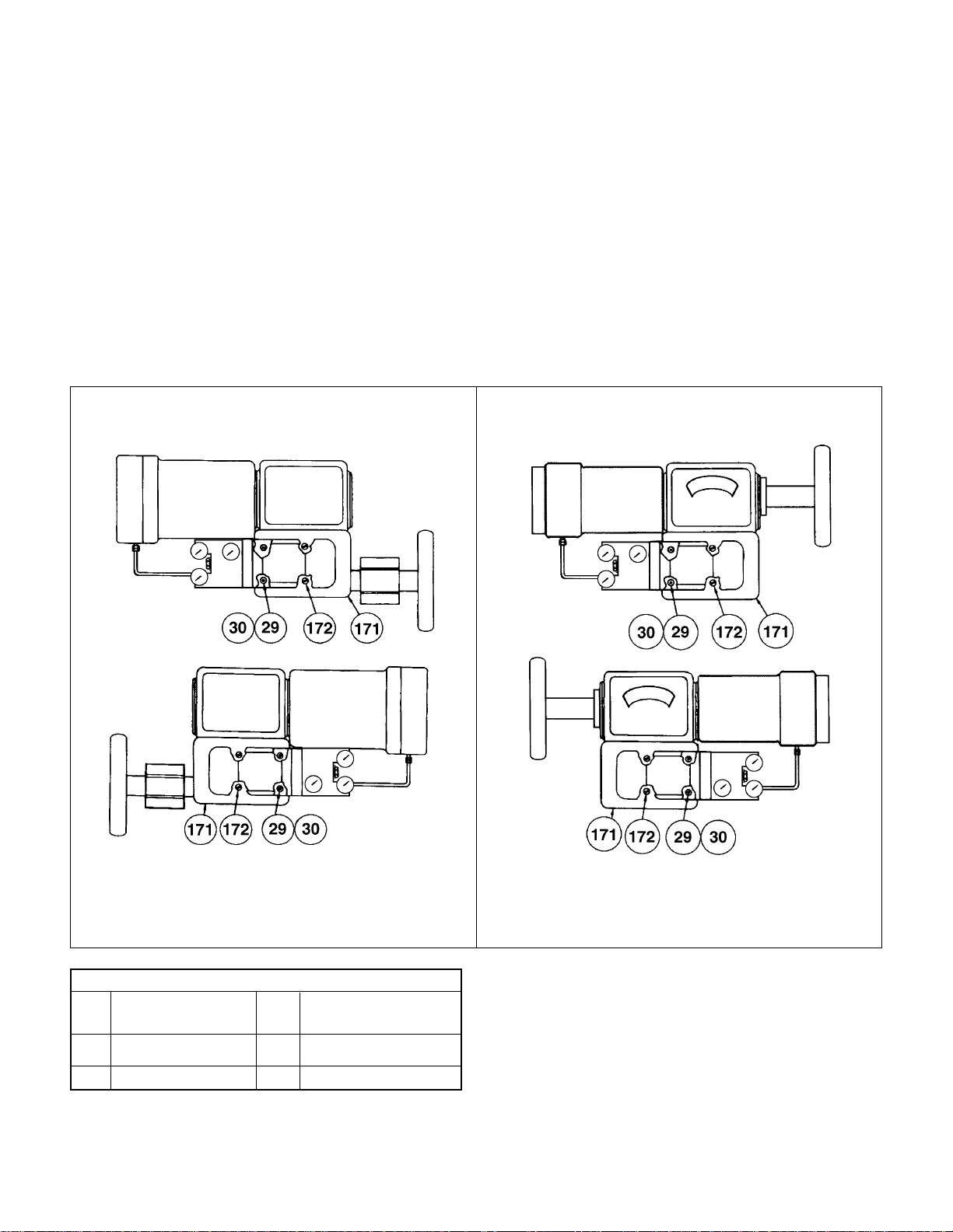
or reverse action (increasing instrument signal produces
a decrease in output pressure). See Figures 2 and 3.
Note that the 4700E is not available with reverse action,
hence if the application demands reverse action, a 4700P
with an external I/P Transducer is required.
CAUTION: When installing a positioner on a
valve, it is necessary to choose the proper valve
action and positioner action. It is absolutely
necessary to place valve travel at the point
corresponding to the low end of the signal range
when removing or installing a cam. At this point,
feedback spring compression is at lowest value
and will facilitate cam removal or installation.
Prior to performing any work, read and under-
stand all items under “General Description and
Operation” and under “Mounting and Orienta-
tion.” Define the scope of work to be performed
and find the appropriate section that should be
followed.
The 4700 series Positioners have the same mounting
and linkage attachment dimensions as the 4600, 4600A,
4600B and 4700B series Positioners but have a different
layout of pneumatic connections. They can replace the
older models if operational requirements are identical and
pneumaticconnectionsarechanged. Themountingdetails
in this instruction cover only the more widely used valves
and actuators.
Cover Removal
The snap-on cover must be removed to access the zero
and span adjustments and to mount the positioner on the
valve.
To remove the cover, depress the latch bar inward as
shown in the figure below, pull cover away from body until
latch tab is clear, then pull along body axis to free the two
top locking tabs.
Optional Bypass Valve
(4700P, Direct Acting Model only)
During normal operation, the instrument signal is applied
directly to the positioner diaphragm and the regulated
supply pressure flows through the pilot valve to or from
the actuator.
The bypass valve module permits the positioner to be
isolated for maintenance while operating the valve directly
with the instrument signal. By turning the nylon bypass
valvetothebypassposition(theraisedarrowonthebypass
valvealignedwiththeword“Bypass”onthefacepositioner
bodyindicatesthisposition),thenormalpositioner“output”
pressure to the actuator is blocked and the instrument
signal is applied both to the positioner diaphragm and the
actuator. Thebypassvalvedoesnotblocksupplypressure
to the pilot. Therefore, the supply line should be shut off
before disassembling the positioner.
WARNING: When a valve (because of high pres-
suredrop)uses a supply pressure higher than 20
psig, the 3-15 psig instrument signal may not be
sufficient to operate the valve when the posi-
tioner is bypassed. Moreover, if the positioner
with a high supply pressure is bypassed sud-
denly, the high pressure in the actuator may
damage the diaphragm and/or the control instru-
ment. Therefore, the bypass valve should be
used only if the positioner supply pressure is 20
psig (140 kPa or 1, 4 bar), or at most 35 psig (240
kPa, or 2, 4 bar), or if the controller is capable of
operating the valve directly. When bypassing a
positioner, ensure that the controller output is
equal to supply required to operate valve.
Installation
Mounting and Orientation (Figures 2-10)
Thevalveisinstalledinthepipelinetooperateinoneoftwo
ways:
Air to Open Air to Close
Close on air failure Open on air failure
(Reverse Action) (Direct Action)
The choice depends on the desired air failure action. This
subject is dealt with in separate actuator instructions. The
positioner can operate either by direct action (increasing
instrumentsignalproducesanincreaseinoutputpressure)
Figure 1 - Cover Removal
Latch
Bar
Locking
Tabs

5
Instruction ES2007 4/98
Models 4700P and 4700E
,,
,,
,,yy
Supply
Pressure
Exhaust
Pressure
Output
Pressure
Signal
Pressure
Direct Positioner Action Reverse Positioner Action
4700P Only
Reverse Positioner Action
4700P Only
Direct Positioner Action
Figure 2 - Rotary
Figure 3 - Reciprocating
For 4700P model only, positioner action can be reversed by simply engaging the proper lobe on the cam and reversing
the follower arm (numbers 1 and 2 above), and the supply and exhaust ports (number 3 above).
,,
,,
yy
yy
,,,
,,,
,,,
yyy
yyy
yyy
,
,
,,
,,
yy
yy
,,yy
,,,
,,,
,,,
yyy
yyy
yyy
,
,
,
,
y
y
,,
,,
yy
yy
,,
,,
yy
yy
,,
,,
yy
yy
,,
,,
yy
yy
Cam
Lever
Arm Feedback
Spring Diaphragm
Pilot
Spring
Bypass
Valve
Pilot
Plug
1
23
Supply Exhaust
3
,,,
,,,
yyy
yyy
,,
,,
,,
yy
yy
yy
,
,
y
y
,,,
,,,
yyy
yyy
,
,
,
y
y
y
,
,
,
,
,,,
,,,
yyy
yyy
,
,
y
y
Cam
Lever
Arm Feedback
Spring
Diaphragm Pilot
Spring
Pilot
Plug
Bypass
Valve
ExhaustSupply
,,
,,
yy
yy
,,
,,
yy
yy
,,,
,,,
yyy
yyy
,,,
,,,
yyy
yyy
,,,
,,,
yyy
yyy
12
3123

Instruction ES2007 4/98
Models 4700P and 4700E
6
87/88 Actuator
Mounting Parts Reference 87/88
Ref. No. Description Ref. No. Description Ref. No. Description
100 Clamp Rod 110 Tubing 29 Screw, .312-18 x 1.25
101 Turnbuckle Screw 111 Positioner 30 Washer, Shakeproof
102 Clevis 112 Male Connector 37 Ring, Retaining
103 Back Lever 113 Cap Screw 38 Cap Screw
104 Clevis Pin 114 Lockwasher 39 Lockwasher
105 Retaining Clip 115 Mounting Bracket 40 Washer, .531 ID
106 Turnbuckle 122 Washer 41 Post Hub
107 Locknut 26 Cam 42 Input Shaft
108 Locknut 27 Washer 135 Instruction Plate
109 Elbow 28 Pan Head Screw
Ref. Nos 109, 110, and 112 are not included in the mounting kit.
Clevis Mounting
Assembly
104 105 122 103
102
106
107101
108
100
Figure 4
Model 88
109
110
111
110
109
109
109
113 114
115
109
109
113 114
115
Model 87

7
Instruction ES2007 4/98
Models 4700P and 4700E
.8 A
1.0 B
1.5 C
2.0 D
2.5 E
Hole Location
Travel
(in.)
Side View
of Bracket
Figure 5
87/88 Actuator
Mounting 4700P and 4700E on
Series 87/88 Actuators.
1. Using screws (113) and lockwashers (114), mount
bracket (115) on actuator with opening located to the right
side of the bracket.
2. Installinputshaft(42)inposthubwitha washer (40) on
each side of the hub and retaining ring (37) on cam end.
3. Mount back lever (103) to input shaft using screw (38)
and lockwasher (39).
4. Install clevis (102), clevis pin (104), washer (122), and
retainingclip (105)intheproper locationontheback lever.
Location is based on valve stroke required.
5. Check Figure 5 for proper mounting location for posi-
tioner on bracket.
6. Mount positioner on bracket using socket head screws
(29) and lockwashers (30).
Note: Back lever must be behind bracket.
7. Mount cam (26) on input shaft using washer (27) and
screw (28) with desired lobe against cam follower.
(Do not mount cam if positioner is reverse action)
8. Connect turnbuckle (106), locknut (107), turnbuckle
screw (101), locknut (108), and clamp rod (100).
EDCBA
105
104 122 103
Back Lever
2.5"
2.0"
1.5"
1.0"
0.8"
Front of
Bracket
(115)
Top view of
4700P and 4700E
Positioner
39
38
30
29
42 3740
28
27
26
4A
4140
135

Instruction ES2007 4/98
Models 4700P and 4700E
8
87U/88U Actuator
Mounting 4700P and 4700E on Series 87U/
88U Actuators.
1. Mount lever (1U) between two jam nuts (11U) on valve
stem.
2. Attach turnbuckle screw (101) to lever (1U).
3. Assemblejamnut(107)toclevis(102).Assembleclevis
to turnbuckle screw (101).
4. Install input shaft (42) in post hub with a washer (40)
on each side of hub and retaining ring (37) on cam end.
5. Attach back lever (103) to shaft with hex head screw
(38) and lockwasher (39).
6. Attach bracket (5U) to positioner with screws (29) and
lockwashers (30).
7. Mount positioner and bracket assembly to actuator
yoke using cap screws (12U) and lockwashers (30).
8. Attach clevis (102) to back lever (103) using clevis pin
(104), retaining clip (105), and washer (122).
9. Mountcam(26)oninput shaftwithdesiredlobeagainst
cam follower using screw (28) and washer (27).
Figure 6
101
107
105
104
122
1U
102
103
Ref. Ref.
No. Description No. Description
1U Lever 39 Lockwasher
5U Bracket 40 Washer, .531 ID
11U Nut 42 Input Shaft
12U Cap Screw 101 Turnbuckle Screw
26 Cam 102 Clevis
27 Washer 103 Back Lever
28 Pan Head Screw 104 Clevis Pin
29 Screw 105 Retaining Clip
30 Lockwasher 107 Locknut
37 Ring, Retaining 122 Washer
38 Cap Screw 135 Inst. Plate
Mounting Parts Reference 87U/88U

9
Instruction ES2007 4/98
Models 4700P and 4700E
Positioner Mounting and Orientation
Camflex®II, Varimax,
™MiniTork®II, Ball II,
and HPBV (Figures 7, 8, 9, and 10)
Thepositionerismountedtoanintermediateplate(171)by
two screws (29) and lockwashers (30) with the gauges
nearest the actuator on Camflex and Varimax and with
gauges away from actuator on Ball II, MiniTork II, and
HPBV. The intermediate mounting plate (171) is held by
two flat-head screws (172) to the bracket.
Note: The cam take-off hole must be centered about
the shaft before tightening mounting screws.
29 Socket Head Screw 172 Mounting Plate Screws
171 Mounting Plate 30 Lockwashers
Ref.
No. Ref.
No.
Mounting Parts Reference
Description Description
Air to Close
Air to Open
Air to Close
Camflex II Varimax
Figure 7 Figure 8
Note: The remainder of the mounting kit parts are used to assemble the cam to the actuator. See section “Mounting Cam Coupling”
on page 18.
Air to Open

Instruction ES2007 4/98
Models 4700P and 4700E
10
Ball II and MiniTork II
(For detail of Positioner Mounting, see Figure 7)
Figure 9
Air to Open Air to Close
High Performance Butterfly Valve (HPBV)
(For detail of Positioner Mounting, see Figure 7)
Figure 10
Air to Open Air to Close

11
Instruction ES2007 4/98
Models 4700P and 4700E
Pneumatic Installation
Note: The output and supply connections for the 4700E/P
are different from those on the 4600A.
Thesepositioners are designedtooperateonly withclean,
dry, oil-free, instrument grade air to ANSI/ASA-57.3 1975
(R1981) or ISA-S7.3-1075 (R1981).
Dew point: At least 18°F (10°C) below
minimum anticipated ambient
temperature
Particulate matter: Filtered to below 5 microns
Oil content: Less than 1 ppm w/w or v/v
Contaminants: Free of all corrosive contaminants
and hazardous gasses, flammable
or toxic
The supply, output, and signal connections, at the back of
themanifold,aretapped1/4"NPT. Thereisalsoanexhaust
connectionwithaplasticsquareheadpluginit. Iftheaction
ofthepositionerisreversed,4700only,thenthesupplyand
exhaust connections must be interchanged. With reverse
action, the“Supply”gaugemustberemovedandreplaced
by a 1/8" NPT plug installed in the supply connnection.
Since the new supply connection has no gauge port,
connect the removed “Supply” gauge to the filter regulator
to indicate regulator output pressure.
Figure 11 shows pneumatic connections for both the
4700Pand4700EPositioners. Notethatthe4700Ehasthe
“Instrument”portsealedbya1/4"NPTPlug. Donotremove
plug or make any other connections to this port.
The use of a Masoneilan filter regulator with a 5 micron
filter is recommended for the air supply. Tubing used for
piping between filter regulator, positioner, and actuator
should be 1/4" minimum, with 3/8" used for larger actuators.
Caution: Do not use pipe thread sealant tapes on
pneumatic fittings, as it tends to shred small
particleswhichcancauseinstrumentmalfunction.
The use of soft setting anaerobic hydraulic seal, such as
Loctite Hydraulic Seal 542, is recommended. Follow
manufacturer’s instructions.
Caution: Do not use an excessive amount, as it
will not set and may migrate into the instrument.
The pneumatic input signal ranges are 3-15 psig (20-100
kPaor207-1034mbar),6-30psig(40-200kPaor414-2068
mbar),and3-27psig(20-180kPaor207-1862mbar). Split
ranges are available. Positioners with 24 psig signal span
(i.e.,6-30psigand3-27psig)requireadifferentdiaphragm
assembly as shown in Figure 19 on page 30.
Maximum allowable air supply pressure to the positioner
varies according to actuator, valve size, and type. See
pressure drop tables in valve catalog to determine correct
positioner supply pressure.
DANGER: Never exceed actuator or positioner
maximum supply pressure. Damage to equip-
ment or injury to personnel may result.

Instruction ES2007 4/98
Models 4700P and 4700E
12
Figure 11
INSTRUMENT
OUTPUT
OUTPUT
VENT
SUPPLY
SIGNAL
SIG DIR SUP
REV EXH
DIR EXH
REV SUP OUT
4700P Reverse Action
INSTRUMENTSUPPLY
OUTPUT
SIG DIR SUP
REV EXH
OUTPUTVENT
SUPPLYSIGNAL
DIR EXH
REV SUP OUT
4700P Direct Action
OUTPUTVENT
SUPPLYPLUG
SUPPLY
OUTPUT
SIG DIR SUP
REV EXH
DIR EXH
REV SUP OUT
4700E Direct Action

13
Instruction ES2007 4/98
Models 4700P and 4700E
Electrical Installation of 4700E
Electricalconnections should be made as shown inFigure
12. The terminals will accept wire sizes up to AWG 14.
The loop controller driving the positioner must be capable
ofsupplying4-20 mA with an output voltage compliance of
at least 5 volts.
The available output voltage of a current source will be
reducedby loop wiring resistance. This canbecheckedby
connecting a resistor of value (250 ohms + Loop Resis-
tance) across the output of the controller and verifying that
at 100% controller output 20 mA is obtainable.
CAUTION:Do not useavoltage source todrive the
positioner as it may cause permanent damage.
Figure 12 - Electrical Connections
INTERNAL
GROUND
SIGNAL
CONNECTIONS
EXTERNAL
CONNECTIONS
WARNING: The positioner must be installed in
accordancewithlocalandnationalcodesofprac-
tice in both general purpose and hazardous area
locations. The electrical components are fully
isolated from ground and therefore grounding is
unnecessaryforfunctionalpurposes.Grounding
maybenecessarytoconformtoinstallationcodes.
The positioner is normally supplied with a 1/2" NPT conduit
entry. (M20 is optional) Internal and external ground
terminals are provided for use if grounding is required.
INTERNAL
GROUND
SIGNAL
CONNECTIONS
EXTERNAL
GROUND

Instruction ES2007 4/98
Models 4700P and 4700E
14
Hazardous Area Installations
The positioner is available in versions suitable for use in
hazardous areas. The labeling on the positioner indicates
correct areas of use.
WARNING: Installation of any hazardous area
equipment must be made in accordance with the
appropriate hazardous area installation codes
and the manufacturer’s installation and operat-
inginstructions.Theusermustmakenochanges
or attempt any repairs of a certified instrument
since this will invalidate the certified design. If a
certified instrument should fail it must be re-
turned to the manufacturer for repair.
Factory Mutual approved version
Explosionproof: Class I, Division 1, Groups B, C, and D.
TemperatureclassificationT6@75°Cambient,T5@85°C
ambient, indoor and outdoor (NEMA Type 4X) hazardous
(classified) locations.
Dust-Ignitionproof: Class II / III, Division 1, Groups E, F,
and G.
Non-Incendive: Class I / II / III, Division 2 Groups A, B, C,
D, F, and G.
Installation must be in accordance with the current edition
of the National Electrical Code ANSI / NFPA-70, any
applicable local codes, and manufacturer’s instructions.
Intrinsically Safe: Class I / II / III, Division 1, Groups A, B,
C, D, E, F, and G hazardous indoor/outdoor NEMA 4X
locations.TemperatureClassificationT4@40°Cambient,
T3B @ 70°C ambient, T3A @ 85°C ambient.
Installation must be in accordance with the current edition
oftheNationalElectricalCodeANSI/NFPA-70,ANSI/ISA
RP 12.6
“Installation of Intrinsically Safe Instrument Sys-
tems in Class I Hazardous (Classified) Locations,”
Figure
14, Installation Drawing 96-115 on page 15, and
manufacturer’s instructions.
CSA (Canadian Standards Association)
approved version
Explosionproof: Class I, Groups B, C, and D Class II,
GroupsE,F,and GandClassIIIrated at30mAmaximum,
28Vdc maximum, with a temperature codeT6@75°C,T5
@ 85°C, Type 4X enclosure.
Division2:Class1,Division2,GroupsA,B,C,andDrated
30 mA maximum and 28Vdc maximum.
Installation must be in accordance with the current edition
of the Canadian National Electrical Code Part I, any appli-
cable local codes and manufacturer’s instructions.
IntrinsicallySafe:ClassI,GroupsA,B,C,andD,ClassII,
Groups E, F, and G, Class III rated at 30 mA maximum 28
Vdc maximum. Temperature code T6 @ 55°C, T4A @
85°C, Type 4X enclosure.
Installation must be in accordance with the current edition
of the Canadian National Electrical Code Part I, Figure 15,
InstallationDrawing96-112onpage16,andmanufacturer’s
instructions.
CENELEC Approved Version
Flameproof: Coded as EEx d IIB + H2
T5 @ Tamb = 70°C
T4 @ Tamb = 85°C
Type N: Coded as Ex N IIC
T4 @ Tamb = -40°C to 80°C
Installation must be in accordance with current editions of
applicable country codes and manufacturer’s instructions.
Intrinsically Safe: Coded as EEx ia IIC T4 @ 80°C.
Installation must be in accordance with current editions of
applicable country codes, Figure 16, Installation Drawing
96-109 on page 17, and manufacturer’s instructions.
Housing Protection Rating IP 66
Split Range Operation
Split ranging permits operation of two valves in sequence
from one 4-20 mA control signal. To accomplish this with
the 4700E, the two positioners are connected in series as
shown in Figure 13, with the actual split ranging done by
propercamsegmentselectionpertablesonpages27-29.
Note:Withthisconfiguration,thevoltageburdenofthe
4-20 mA controller is 10 V instead of 5 V.
Figure 13 - Split Range
Controller
Positioner
No. 1
Positioner
No. 2

15
Instruction ES2007 4/98
Models 4700P and 4700E
Figure 14 - FM Installation

Instruction ES2007 4/98
Models 4700P and 4700E
16
Figure 15 - CSA Installation

17
Instruction ES2007 4/98
Models 4700P and 4700E
Figure 16 - CENELEC Installation

Instruction ES2007 4/98
Models 4700P and 4700E
18
Calibration
Warning: Before commencing any calibration or
maintenanceprocedureonthesepositioners,en-
sure that the valves under control are isolated
from the controlled process and that the area is
verified as nonhazardous.
General
The Model 4700P and 4700E positioner, when factory
mounted, has been calibrated for the proper valve, valve
action, and positioner action. If, for any reason, the cam
holder (36) setting has been disturbed (i.e., a change of
positioner action, field mounting, maintenance, etc.), it is
necessary to follow all steps of the calibration instructions,
according to desired actuator action and positioner action.
Calibration may entail just a simple adjustment or a com-
plete field mount. Define the scope of work and follow the
applicable sections.
Caution: Do not attempt to remove cam if cam is
not at low signal line of lobe (low end of range).
Refer to calibration instruction for proper valve
action and positioner action before removing or
replacing cam and tightening set screws (35) to
proper torque.
Zero Adjustment (Figure 19 & 20)
The zero adjustment is made with the zero nut (4B). When
the positioner is installed and the pneumatic circuits are
connectedapplylow instrument signal (i.e., 3 psi for 4700P,
4mAfor4700E),releaselocknut(4C)andturnzeronut(4B)
toadjustvalveplugtoproperposition(openorclosed).Then
tighten zero lock nut (4C).
Note: Do not attempt to adjust zero nut with signal
above low end of signal range. If valve is seated at low
Mounting Cam Coupling
(Figure 19 & 20)
The cam coupling (34), used on rotary actuators, is posi-
tioned on the shaft with the key engaged in the shaft slot
and the set screws (35) to the top and side. The coupling
hold-down screw (32) with the lockwasher (33) is torqued
to 125 inch-lbs.
Mounting Cam
The cam holder (36) and cam (26) are positioned on the
camcoupling(34)sothatthedesiredcamlobe’slowsignal
line is properly adjusted on the cam follower (4A). Proper
adjustment is achieved when:
1. Thedesiredcamlobe’slowsignallineisinalignmentwith
the “raised reference line” on the positioner (Figure 19).
2. The cam is centered between the two arms of the cam
lever S/A (3) (Figure 19).
Changing Lever S/A Orientation
(see pages 27 - 29)
If lever S/A (3) must be changed, remove screw (28)
and washer (27), and cam (26) from cam shaft. Remove
retaining ring (17) and flat washer (16). Remove lever S/A
(3) from pivot post. Lift and rotate lever S/A (3) on spring
end 180°to desired position. (Do not rotate spring end;
socket head screw on spring must face outward.) Replace
flat washer (16) and retaining ring (17) on pivot post.
Lever S/A Orientation (see pages 27 - 29)
TherelativepositionoftheleverS/A(3)for a selected cam
lobemustbecorrect.TheleverS/Acanbemountedwithits
pivot post to the left or right of the cam center.
Lobe Identification
Figure 17
1
2
3
4
5
6
Lobe
(Lobe 3)
Low Signal Line
(Lobe 1)
Low Signal Line
(Lobe 1)
Lobe
(Lobe 3)
Lobe Lines
(Lobe 6)
Lobe Lines
(Lobe 2)
90°
1
2
3
Note: The low signal line is the shortest
lobe line defining a particular lobe.

19
Instruction ES2007 4/98
Models 4700P and 4700E
end of signal range, after making zero adjustment,
decrease signal below low end of signal range and
slowlyincreasesignaltoensurevalveplugliftsoffseat
at desired signal. If valve is open at low end of signal
range, adjust zero so valve indicates “Open” on travel
indicator scale.
Read field mounting and complete calibration in-
struction (
∑
F or rotary valves) before attempting to
adjust zero.
Span Adjustment (Figure 19 & 20)
If the valve does not fully stroke for a full signal span, the
feedbackspringrateistoohigh. Loosenscrew(8)andturn
spring (5) on the spring end (4) to increase the number of
activecoilsanddecreasethespringrate.Conversely,iffull
stroke is reached prior to full signal span, turn the spring
to decrease the number of active coils and increase the
spring rate.
Adjustment of +1/4turn of the spring changes its rate by
approximately +10%.
After making a spring adjustment, it will be necessary to
reset the zero. This is done by turning the zero adjustment
(4B), and tightening zero locknut (4C).
Example: If the number of active coils is increased making
the spring longer, it will be necessary to readjust the zero
nut to compensate for the increased spring length.
When span adjustment has been completed, retighten the
spring locking socket head screw (8).
Caution: When installing positioner with cam in
place, check the position of the spring (5) on
diaphragm S/A (9) to ensure that it is centered on
the diaphragm.
Cam Lobe Change
If it is necessary to change the cam lobe only (without
changingactuatoractionorpositioneraction)thenproceed
as follows:
Note: Do not disturb cam holder (36) setting on rotary
actuators. [i.e. do not touch set screws (35)]
Caution: If cam is not at low signal line on lobe
(lowendofrange),donotattempttoremovecam.
Thecam mustbe atlow signal line.Select correct
actuator and positioner action and proceed as
follows.
Air to Open/Direct Acting Positioner (Figure 19 & 20)
1. Shut off supply pressure and signal to positioner.
Valveis now closedandcam(26) isatlowsignal line
on lobe.
2. With cam at low signal line remove screw (28) and
washer (27). Note the relative position of the cam
lobe being changed and then remove the cam (26).
3. Select the desired cam lobe and replace cam (26)
on cam shaft with low signal line of desired lobe
againstcamfollower.Ensurethenewlyselectedcam
lobeis inthesame relativepositionasthe lobenoted
in Step 2.
4. Replacewasher(27)and screw (28). Turn on supply
pressure and signal to positioner. Check zero and
spanadjustment.(Refertozeroandspanadjustment
section.)
Air to Open/Reverse Acting Positioner (Figure 19)
1. Shut off supply pressure and signal to positioner.
Valveisnowclosedandcam(26)isathighsignalline
on lobe. Do not remove.
2. Run an independent regulated air line to the valve
actuator in place of positioner output line. Slowly
apply proper air pressure through the regulator to
open the valve. Do not exceed designated supply
pressure.(Handwheelmaybeusedtoopenthevalve
inplaceofregulatedairline).Alignthetravelindicator
withthe“open”endoftravelscale.Donotovertravel.
Cam is now at low signal line on lobe.
3. With cam at low signal line remove screw (28) and
washer (27). Note the relative position of the cam
lobe being changed and then remove the cam (26).
4. Select the desired cam lobe and replace cam (26)
on cam shaft with low signal line of desired lobe
againstcamfollower.Ensurethatthe newlyselected
cam lobe is in the same relative position as the lobe
in Step 3.
5. Replace washer (27) and screw (28). Reduce pres-
sureappliedinStep2tozero(backoffthehandwheel
ifhandwheelwasused).Disconnecttheindependent
regulated air line to actuator and connect positioner
output line. Connect supply pressure and signal to
positioner. Check zero and span adjustment. (Refer
to zero and span adjustment section.)
Air to Close/Direct Acting Positioner (Figure 19 & 20)
1. Shut off supply pressure and signal to positioner.
Valve is now open and cam (26) is at low signal line
on lobe.

Instruction ES2007 4/98
Models 4700P and 4700E
20
2. With cam at low signal line remove screw (28) and
washer (27). Note the relative position of the cam
lobe being changed and then remove the cam (26).
3. Select the desired cam lobe and replace cam (26)
on cam shaft with low signal line of desired lobe
againstcamfollower.Ensurethenewlyselectedcam
lobeis inthesame relativepositionasthe lobenoted
in Step 2.
4. Replacewasher(27)andscrew(28).Checkzeroand
spanadjustment.(Refertozeroandspanadjustment
section).
Air to Close/Reverse Acting Positioner (Figure 19)
1. Shut off supply pressure and signal to positioner.
Valve is now open and cam (26) is at high signal line
on lobe. Do not remove.
2. Run an independent regulated air line to the valve
actuator in place of positioner output line.
Slowly apply proper air pressure through the regula-
tor to shut the valve. Do not exceed designated
supply pressure. (Handwheel may be used to close
thevalveinplaceofregulatedairline.)Alignthetravel
indicatorwith the “closed”endoftravelscale. Cam is
now at low signal line on lobe.
3. With cam at low signal line remove screw (28) and
washer (27). Note the relative position of the cam
lobe being changed and then remove the cam (26).
4. Select the desired cam lobe and replace cam (26)
on cam shaft with low signal line of desired lobe
againstcamfollower(4A).Ensurethenewlyselected
cam lobe is in the same relative position as the lobe
noted in Step 3.
5. Replace washer (27) and screw (28). Reduce pres-
sureappliedinStep2tozero(backoffthehandwheel
ifhandwheelwasused).Disconnecttheindependent
regulated air line to actuator and connect positioner
output line. Connect supply pressure and signal to
positioner. Check zero and span adjustment. (Refer
to zero and span adjustment section.)
Field Mounting and Complete
Calibration, Rotary Actuators
The following instructions are to be followed for mounting
and calibration of the 4700P and 4700E positioner. Define
the proper valve action and positioner action. If the posi-
tionerisnotonthevalve,seeFigure20tomountpositioner
and cam coupling. Once the positioner body is assembled
onthevalveandthecouplingisonthevalveshaft,proceed
to the proper section below.
Air to Open/Direct Acting Positioner (Figure 19 & 20)
1. Do not connect air supply or signal to the positioner.
Valve is closed.
2. Place lever S/A (3) to proper side (left or right) as
designatedbytheappropriatecamselectiontablefor
valve in question.
3. With valve closed, place cam holder (36) with truarc
ring (37) into cam coupling (34).
4. Place the cam (26) onto the cam holder (36) so that
the selected cam lobe is facing forward and will rest
on the cam follower. (See appropriate table for cam
selection.) Secure cam to cam holder with washer
(27) and screw (28). Tighten the screw (28) while
holding the cam (26).
5. With the valve closed, place the desired cam lobe's
low signal line on the cam follower (4A). With the low
signal line resting on the cam follower, sight across
thefaceofthecamtotheraisedreferencelineonthe
positioner case and align. (Low signal line and refer-
ence line.) Center cam between the two arms of the
lever S/A (3), then tighten set screws (35) to 87 inch-
lbs torque. (See Figure 19 for cam mounting.)
6. Connect air supply and signal to positioner. Connect
positioner output to valve actuator. Refer to connec-
tion diagram. Adjust signal to low end of signal
(i.e., 3 psig for a 3-15 psig range 4700P; 4 mA for
4-20 mA 4700E).
7. Adjustzeroandspan.(Refertozeroandspanadjust-
ment section.)
Air to Open/Reverse Acting Positioner (Figure 19)
1. Do not connect air supply or signal to the positioner.
Valve is closed.
2. Place lever S/A (3) to proper side (left or right) as
designatedbytheappropriatecamselectiontablefor
valve in question.
3. Run an independent regulated air line to the valve
actuator in place of positioner output line. Slowly
apply proper air pressure through the regulator to
openthevalve.(Handwheelmaybeusedtoopenthe
valve in place of regulated air line.) Align the travel
indicator with the “open” end of travel scale. Do not
over travel.
4. Place cam holder (36) with truarc ring (37) into cam
coupling (34).
5. Place the cam (26) onto the cam holder (36) so that
the selected cam lobe is facing forward and will rest
on the cam follower. See appropriate table for cam
This manual suits for next models
1
Table of contents
Other Dresser Valve Positioner manuals
Popular Valve Positioner manuals by other brands

halstrup-walcher
halstrup-walcher PS*3**DN series instruction manual

tissin
tissin TS800 Series instruction manual

VAC
VAC V200 POSITIONER Mounting instructions

Samson
Samson FOUNDATION 3730-5 Mounting and operating instructions

SMC Networks
SMC Networks KQ2 Series instruction manual

Genebre
Genebre 5950 00 Installation, operation and maintenance manual