GE Baker Hughes Masoneilan SVI FF User manual

Masoneilan*
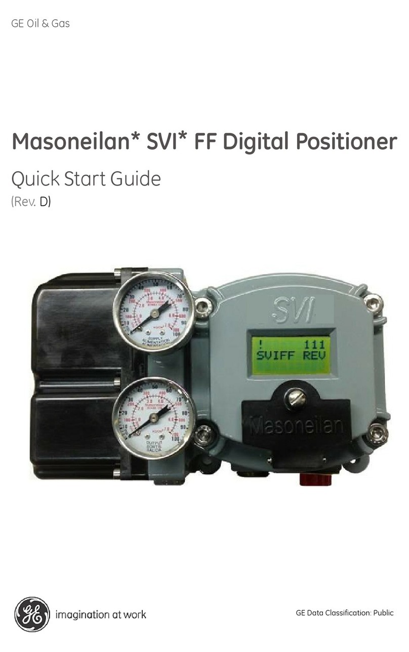
SVI*FF Digital Positioner
Advanced Performance
Installation and Operation Manual (Rev F)
BHGE Data Classification: Public

About this Guide
This instruction manual applies to the following instruments and approved software:
SVI FF
with firmware version 1.0.0.1 or higher
with ValVue* version 3.0
with handheld communicator with DD published for SVI FF
The information contained in this manual, in whole or part, shall not be transcribed or copied without BHGE’s
written permission.
In no case does this manual guarantee the merchantability of the positioner or the software or its adaptability
to a specific client needs.
Please report any errors or questions about the information in this manual to your local supplier or visit
valves.bhge.com.
DISCLAIMER
THESE INSTRUCTIONS PROVIDE THE CUSTOMER/OPERATOR WITH IMPORTANT PROJECT-SPECIFIC REFERENCE
INFORMATION IN ADDITION TO THE CUSTOMER/OPERATOR’S NORMAL OPERATION AND MAINTENANCE PROCEDURES.
SINCE OPERATION AND MAINTENANCE PHILOSOPHIES VARY, BHGE (BAKER HUGHES, A GE COMPANY AND ITS
SUBSIDIARIES AND AFFILIATES) DOES NOT ATTEMPT TO DICTATE SPECIFIC PROCEDURES, BUT TO PROVIDE BASIC
LIMITATIONS AND REQUIREMENTS CREATED BY THE TYPE OF EQUIPMENT PROVIDED.
THESE INSTRUCTIONS ASSUME THAT OPERATORS ALREADY HAVE A GENERAL UNDERSTANDING OF THE REQUIREMENTS
FOR SAFE OPERATION OF MECHANICAL AND ELECTRICAL EQUIPMENT IN POTENTIALLY HAZARDOUS ENVIRONMENTS.
THEREFORE, THESE INSTRUCTIONS SHOULD BE INTERPRETED AND APPLIED IN CONJUNCTION WITH THE SAFETY RULES
AND REGULATIONS APPLICABLE AT THE SITE AND THE PARTICULAR REQUIREMENTS FOR OPERATION OF OTHER
EQUIPMENT AT THE SITE.
THESE INSTRUCTIONS DO NOT PURPORT TO COVER ALL DETAILS OR VARIATIONS IN EQUIPMENT NOR TO PROVIDE FOR
EVERY POSSIBLE CONTINGENCY TO BE MET IN CONNECTION WITH INSTALLATION, OPERATION OR MAINTENANCE.
SHOULD FURTHER INFORMATION BE DESIRED OR SHOULD PARTICULAR PROBLEMS ARISE WHICH ARE NOT COVERED
SUFFICIENTLY FOR THE CUSTOMER/OPERATOR'S PURPOSES THE MATTER SHOULD BE REFERRED TO BHGE.
THE RIGHTS, OBLIGATIONS AND LIABILITIES OF BHGE AND THE CUSTOMER/OPERATOR ARE STRICTLY LIMITED TO THOSE
EXPRESSLY PROVIDED IN THE CONTRACT RELATING TO THE SUPPLY OF THE EQUIPMENT. NO ADDITIONAL
REPRESENTATIONS OR WARRANTIES BY BHGE REGARDING THE EQUIPMENT OR ITS USE ARE GIVEN OR IMPLIED BY THE
ISSUE OF THESE INSTRUCTIONS.
THESE INSTRUCTIONS ARE FURNISHED TO THE CUSTOMER/OPERATOR SOLELY TO ASSIST IN THE INSTALLATION,
TESTING, OPERATION, AND/OR MAINTENANCE OF THE EQUIPMENT DESCRIBED. THIS DOCUMENT SHALL NOT BE
REPRODUCED IN WHOLE OR IN PART TO ANY THIRD PARTY WITHOUT THE WRITTEN APPROVAL OF BHGE.
Copyright
Copyright 2019 by Baker Hughes, a GE company LLC. All rights reserved. PN 720023978-888-0000 Rev. F.
All information contained herein is believed to be accurate at the time of publication and is subject to change
without notice.

Masoneilan SVI FF Instruction Manual =|3
© 2019 Baker Hughes, a GE company, LLC. All rights reserved.
Document Changes
Version/Date Changes
A/03-2014 Original release
B/05-2014 Made changes to specification for Conformity, Linearity and Repeatability.
Made changes to the Remote Positioner installation section,
C/05-2014 Made formatting changes.
D/06-2014 Omitted Link Master chapter.
Made modifications to the Transducer Blocks Parameters table.
Made modifications to the Foundation Fieldbus: Process Example appendix.
Made modifications to the Fault State Processing appendix.
Removed Remote Position Sensor section from install. Now a standalone
manual.
E/08-2017 Added Appendix for Continuous Valve Diagnostics Concept.
Made modifications to Transducer Block Parameters table.
Added Diagnostics Comparison table to Introduction.
Modified the Adv Setup pushbutton menu.
Added LO mode appendix.
F/07-2019 Added Configuring the SVI FF and a Yokogawa Centum DCS.
Updated Troubleshooting.
Changed graphics for DCS switches installation.
Updated download site url.

© 2019 Baker Hughes, a GE company, LLC. All rights reserved.
4 | BHGE
Contents
1. Safety Information ........................................................................................................................................................................... 9
Safety Symbols ............................................................................................................................................................................... 9
SVI FF Product Safety.................................................................................................................................................................10
2. Introduction ......................................................................................................................................................................................13
ValVue Software...........................................................................................................................................................................14
ValVue Standard Edition ..................................................................................................................................................14
Operational Overview................................................................................................................................................................14
SVI FF Features .............................................................................................................................................................................15
Available Options.................................................................................................................................................................16
Characterization ..................................................................................................................................................................16
Control Sets............................................................................................................................................................................16
Continuous Diagnostics ...................................................................................................................................................17
Diagnostic Versions............................................................................................................................................................19
Block Modes ...................................................................................................................................................................................20
Resource Block Modes......................................................................................................................................................20
Transducer Block Modes..................................................................................................................................................20
Overview of Available Tools....................................................................................................................................................22
Principle of Operation................................................................................................................................................................23
Physical and Operational Description................................................................................................................................24
Electronics Module..............................................................................................................................................................24
Output Switch........................................................................................................................................................................25
Pneumatic Module..............................................................................................................................................................26
Optional Display and Pushbuttons..............................................................................................................................29
Link Active Scheduler.................................................................................................................................................................29
About This Manual.......................................................................................................................................................................30
Conventions Used in This Manual................................................................................................................................30
3. Quick Start .........................................................................................................................................................................................31
Step 1: Install the Positioner on the Valve........................................................................................................................31
Step 2: Connect Pressure Supply..........................................................................................................................................31
Step 3: Wire the SVI FF...............................................................................................................................................................32
Step 4: Set Tag and Address...................................................................................................................................................32
Step 5: Basic Configuration.....................................................................................................................................................33
Step 6: Run Find Stops METHOD...........................................................................................................................................34
Step 7: Run Auto Tune METHOD ...........................................................................................................................................34
Downloads......................................................................................................................................................................................34
4. Mechanical Installation ...............................................................................................................................................................35
Overview ..........................................................................................................................................................................................35
SVI FF Positioner Types .............................................................................................................................................................35
Single Acting Positioner Description...........................................................................................................................35
Double Acting Positioner Description ........................................................................................................................41

Masoneilan SVI FF Instruction Manual =|5
© 2019 Baker Hughes, a GE company, LLC. All rights reserved.
Installation......................................................................................................................................................................................44
Pre-Installation Issues.......................................................................................................................................................44
Installation Steps.................................................................................................................................................................46
Installation Notes ................................................................................................................................................................47
Control Sets Configuration..............................................................................................................................................48
Mounting the SVI FF on Rotary Valves ......................................................................................................................50
Mounting the SVI FF on Reciprocating Valves.......................................................................................................55
Dismantling the SVI FF from Reciprocating Valves.............................................................................................58
Installing the SVI FF for Double- Acting Operation..............................................................................................59
Connecting the Tubing and Air Supply......................................................................................................................62
Wiring the SVI FF..................................................................................................................................................................65
5. Check Out and Power Up ...........................................................................................................................................................73
Overview..........................................................................................................................................................................................73
Check Out Procedures ..............................................................................................................................................................73
Physical Inspection.............................................................................................................................................................73
Check the Electronic Module Connections..............................................................................................................77
Operational Checkout ...............................................................................................................................................................77
Connect to the H1 Network............................................................................................................................................77
Power Up the SVI FF...........................................................................................................................................................78
6. Failsafe/OOS Considerations ....................................................................................................................................................79
Failsafe Mode vs. OOS Mode..................................................................................................................................................79
Exiting Failsafe Using AMS..............................................................................................................................................81
7. Maintenance ....................................................................................................................................................................................83
SVI FF Maintenance and Repair............................................................................................................................................83
Repair........................................................................................................................................................................................83
Tools Needed.........................................................................................................................................................................83
Display Cover Removal and Installation...................................................................................................................83
I⁄P Module Removal and Installation ..........................................................................................................................85
Relay Removal and Installation....................................................................................................................................88
Adjusting I/P Zero................................................................................................................................................................88
Connecting Components to the Electronics Module..........................................................................................88
Repair by Replacement ............................................................................................................................................................89
Internal Diagnostics ...................................................................................................................................................................89
FAILSAFE Mode.....................................................................................................................................................................89
Viewing Firmware Versions ....................................................................................................................................................90
Spare Parts .....................................................................................................................................................................................91
Appendix A. Specifications and References ...........................................................................................................................95
Physical and Operational Specifications..........................................................................................................................95
Appendix B. About Fieldbus ........................................................................................................................................................ 103
Outline............................................................................................................................................................................................ 103
Internal Structure of SVI FF.................................................................................................................................................. 103
Logical Structure of Each Block......................................................................................................................................... 105
System Configuration............................................................................................................................................................. 106
Connection of Devices ................................................................................................................................................... 107

© 2019 Baker Hughes, a GE company, LLC. All rights reserved.
6 | BHGE
Integration of DD ......................................................................................................................................................................107
Appendix C. Foundation Fieldbus: Process Example .......................................................................................................109
Overview .......................................................................................................................................................................................109
Reference Model Process......................................................................................................................................................109
P & I D.............................................................................................................................................................................................110
Function Block Links................................................................................................................................................................111
Device Operational States and Block Modes...............................................................................................................113
Block Modes........................................................................................................................................................................113
Multiple Modes and States..........................................................................................................................................115
Examples of Operational States................................................................................................................................115
Transferring Modes .........................................................................................................................................................116
RCas Mode...........................................................................................................................................................................116
Appendix D. Troubleshooting .....................................................................................................................................................117
What to Do First ........................................................................................................................................................................117
Troubleshooting Communications...................................................................................................................................118
Troubleshooting Function Block Parameters ..............................................................................................................119
Troubleshooting Valve Control...........................................................................................................................................120
Troubleshooting Auto Tuning..............................................................................................................................................123
Troubleshooting Tuning.........................................................................................................................................................125
Troubleshooting Position, Pressure, and Temperature Sensors.........................................................................126
Appendix E. Using the Pushbuttons and Digital Interfaces ..........................................................................................127
Overview .......................................................................................................................................................................................127
Local Display and Pushbuttons .................................................................................................................................127
Handheld Communicator.............................................................................................................................................128
ValVue....................................................................................................................................................................................128
Pushbuttons and Local Display..........................................................................................................................................128
Pushbuttons........................................................................................................................................................................129
Pushbutton Locks and Configuration-Lock Jumper ........................................................................................130
Hardware Configuration Lock ....................................................................................................................................130
Hand Held Communicator ...................................................................................................................................................131
Check-out with a Handheld Communicator........................................................................................................132
ValVue ............................................................................................................................................................................................133
Installation of ValVue Software, and Registration ............................................................................................133
Installation of Cover ................................................................................................................................................................133
Display Menus ............................................................................................................................................................................133
NORMAL Operating Mode Menus .............................................................................................................................133
BAS SETUP Menu...............................................................................................................................................................134
ADV SETUP Menu..............................................................................................................................................................137
VIEW DATA Menu..............................................................................................................................................................139
VIEW ERROR Menu...........................................................................................................................................................142
MAN POS Menu..................................................................................................................................................................148
METHOD Menu...................................................................................................................................................................148
Appendix F. Transducer Block Parameters ..........................................................................................................................149
Appendix G. Static Parameters During Restore to Defaults ........................................................................................197

Masoneilan SVI FF Instruction Manual =|7
© 2019 Baker Hughes, a GE company, LLC. All rights reserved.
Appendix H. Notes on Characterization ................................................................................................................................ 199
Valve Over/Under Reaction Near Endpoints ............................................................................................................... 199
Configuration of Position Limits, Position Rate Limits and FINAL_VALUE_CUTOFF and Characterization
200
Relationship Between Alerts, Alert Response Type and Block Error......................................................... 202
Appendix I. Fault State Processing .......................................................................................................................................... 203
Initiate Fault State from the Host ............................................................................................................................. 203
Fault State Conditions Detected by AO Block..................................................................................................... 204
Fault State Conditions Detected by Transducer Block ................................................................................... 204
Fault State Condition is Detected and Processed by the Position Control Hardware and Software
205
Appendix J. Configuring the SVI FF and a Yokogawa Centum DCS ......................................................................... 207
Purpose and Scope.................................................................................................................................................................. 207
Status of SVI FF interoperability with Yokogawa DCS............................................................................................. 208
Special Notes When Working with Yokogawa DCS ......................................................................................... 208
Procedure..................................................................................................................................................................................... 209
1. Preparation for Device Connection .................................................................................................................... 209
2. Connecting the SVI FF ............................................................................................................................................... 215
3. Edit Block Parameters............................................................................................................................................... 217
4. Set Device Information ............................................................................................................................................. 220
Appendix K. Views ........................................................................................................................................................................... 225
Views .............................................................................................................................................................................................. 225
Appendix L. References ................................................................................................................................................................ 229
Appendix M. Continuous Valve Diagnostics Concept ..................................................................................................... 231
Introduction................................................................................................................................................................................. 231
Off Line Diagnostics ........................................................................................................................................................ 232
On Line Diagnostics ........................................................................................................................................................ 232
Continuous Diagnostics......................................................................................................................................................... 233
Positioner Diagnostics ................................................................................................................................................... 233
Valve/Actuator Diagnostics......................................................................................................................................... 234
Supporting Information for Diagnostic Configuration.................................................................................... 237
Application Specific Categorization......................................................................................................................... 241
Reporting Diagnostic Condition to the Host ................................................................................................................ 242
Diagnostic Events Reported by Block Error ......................................................................................................... 242
Diagnostic Events Reported by Alarms.................................................................................................................. 244
Diagnostic Events Reported According to FF-912 Field Diagnostic Profile Specification.............. 246
Discrete Switch Configuration ................................................................................................................................... 249
Processing to DI Block.................................................................................................................................................... 249
Conclusion ................................................................................................................................................................................... 249
Appendix N. Changing Out of LO Mode ................................................................................................................................ 251
Local Display............................................................................................................................................................................... 251
Device DTM.................................................................................................................................................................................. 252
Handheld...................................................................................................................................................................................... 253
DD Method................................................................................................................................................................................... 256

© 2019 Baker Hughes, a GE company, LLC. All rights reserved.
8 | BHGE
DD Host .........................................................................................................................................................................................258
Appendix O. Air to Open/Air to Close Configuration ........................................................................................................259
Standard DD-based Configuration Tool: Transducer Block - Fail Action Parameter................................260
SVI FF DTM....................................................................................................................................................................................261

© 2019 Baker Hughes, a GE company, LLC. All rights reserved. Masoneilan SVI FF Instruction Manual =|9
1. Safety Information
This section provides safety information including safety symbols that are used on the SVI FF
and the safety symbol definition.
Read this entire section before installation and operation.
Safety Symbols
SVI FF instructions contain WARNINGS, CAUTIONS labels and Notes, where necessary, to alert
you to safety related or other important information. Total compliance with all WARNING, and
CAUTION notices is required for safe operation.
Indicates a potentially hazardous situation, which if not avoided could result in
serious injury.
Indicates a potentially hazardous situation, which if not avoided could result in
property or data damage.
Indicates important facts and conditions.
CAUTION
WARNING
CAUTION
NOTE

© 2019 Baker Hughes, a GE company, LLC. All rights reserved.
10 | BHGE
SVI FF Product Safety
The SVI FF digital valve positioner is intended for use with industrial compressed air or, natural
gas systems only.
Ensure that an adequate pressure relief provision is installed when the application of system
supply pressure could cause peripheral equipment to malfunction. Installation must be in
accordance with local and national compressed air and instrumentation codes.
General installation, maintenance or replacement
Products must be installed in compliance with all local and national codes and
standards by qualified personnel using safe site work practices. Personal Protective
Equipment (PPE) must be used per safe site work practices.
Ensure proper use of fall protection when working at heights, per safe site work
practices. Use appropriate safety equipment and practices to prevent the dropping of
tools or equipment during installation.
Under normal operation, compressed supply gas is vented from the SVI FF to the
surrounding area, and may require additional precautions or specialized installations.
Intrinsically Safe Installation
Products certified as explosion proof or flame proof equipment or for use in intrinsically safe
installations MUST BE:
Installed, put into service, used and maintained in compliance with national and local
regulations and in accordance with the recommendations contained in the relevant
standards concerning potentially explosive atmospheres.
Used only in situations that comply with the certification conditions shown in this
document and after verification of their compatibility with the zone of intended use
and the permitted maximum ambient temperature.
Installed, put into service and maintained by qualified and competent professionals
who have undergone suitable training for instrumentation used in areas with
potentially explosive atmospheres.
Installations using natural gas are Zone 0 or Div 1 installations.
NOTE

Masoneilan SVI FF Instruction Manual =|11
© 2019 Baker Hughes, a GE company, LLC. All rights reserved.
Use only genuine replacement parts which are provided by the manufacturer, to guarantee
that the products comply with the essential safety requirements of the European Directives.
Changes to specifications, structure, and components used may not lead to the revision of
this manual unless such changes affect the function and performance of the product.
Before using these products with fluids/compressed gases other
than air or for non-industrial applications, consult the factory. This
product is not intended for use in life support systems.
Under certain operating conditions, the use of damaged
instruments could cause a degradation of the performance of the
system, which can lead to personal injury or death.
Under certain operating conditions the SVI FF High Flow unit can
produce noise levels greater than 85 dBA. Perform proper site
monitoring and testing to verify the need for engineering or
administrative controls to eliminate or reduce hazardous noise
levels.
Installation in poorly ventilated confined areas, with any potential
of gases other than oxygen being present, can lead to a risk of
personnel asphyxiation.
WARNING

This page intentionally left blank.

© 2019 Baker Hughes, a GE company, LLC. All rights reserved. Masoneilan SVI FF Instruction Manual =|13
2. Introduction
The SVI FF (Smart Valve Interface) is the next generation of Masoneilan’s intelligent digital valve
positioners with the FOUNDATION Fieldbus interface. The SVI FF is a high performance, digital
valve positioner that combines a local display with remote communication and diagnostic
capabilities. The SVI FF offers a multitude of options that fulfill the broadest range of
applications, using the FF protocol. The High Flow version is capable of 2.2 Cvair throughput.
An optional pushbutton and LCD display enables local operations of calibration and
configuration functions. Remote operations can be performed with ValVue (Version 3) software,
with any FDT-based frame application or any FF Registered host interface that has been
pre-loaded with the Device Description files (DD) for SVI FF.
The SVI FF is provided with Masoneilan’s ValVue software. The user-friendly interface facilitates
the setup and diagnostics of a control valve.
Figure 1 SVI FF

© 2019 Baker Hughes, a GE company, LLC. All rights reserved.
14 | BHGE
ValVue Software
Not only does ValVue provide the ability to quickly and easily set up the SVI FF you can also
monitor operation and diagnose problems with ValVue’s advanced diagnostic capabilities.
ValVue Standard Edition
ValVue Standard Edition software is downloadable and is used with each SVI FF for positioner
calibration and configuration. ValVue Standard Edition software is freeware. It provides
functions to properly set up and start up an SVI FF digital valve positioner on any type of
control valve, along with diagnostics, Sequence, Audit Trial, and Monitoring Device. After a 30
day trail period the Sequence, Audit Trial, and Monitoring Device functionality will become
inoperable.
Contact
For the most recent software visit our SVI FF web site at:
https://valves.bhge.com/resource-center.
Operational Overview
The SVI FF is a smart electro-pneumatic positioner that:
1. Receives a digital setpoint from the controller and compares the setpoint input to the
valve position reported by the position sensor.
2. Uses the position control algorithm to analyze the difference between the position
setpoint and position feedback and sets a servo signal for the I/P converter.
3. Uses the output pressure of the I/P, which is amplified by a pneumatic relay that drives the
actuator. Once the error between the setpoint and the valve position feedback is
eliminated, no other correction is applied to the servo signal in order to maintain valve
position.
The local explosion proof LCD/Buttons (if equipped) display provides information about the
device. The LCD can display data from blocks on other devices, if the system is so configured.
The switch board provides a user-configurable discrete output, which is optionally used to
indicate different controller states.

Masoneilan SVI FF Instruction Manual =|15
© 2019 Baker Hughes, a GE company, LLC. All rights reserved.
SVI FF Features
The SVI FF Digital Valve Positioner is suitable for installation indoors or outdoors, and in a
corrosive industrial or marine environment and is equipped with the following features:
Extreme Accuracy, Reliability and Digital Precision
Automated Valve Commissioning
Precise, Quick, Responsive Control of Valve Position
Valve Position Auto Tuning
One Model for Rotary or Reciprocating Valves
Local Operation⁄calibration⁄configuration with Optional Flameproof Push Buttons and
LCD Digital Display
Compatible with Air-to-Close or Air-to-Open Actuators
Non-contact Magnet Coupled (Hall Effect) Position Sensing for Rotary and
Reciprocating Control Valves
Sealed Housing with No Moving Shafts, No Shaft Penetration, and Fully Potted
Electronics
Uniform Hazardous Area Approvals for ATEX, FMc, and FM with Other Approvals
Available Upon Request
Local, On-line Diagnostic Condition Monitor: Total Stem Travel, Number of Valve Cycles,
Predictive Maintenance Data
Advanced Valve Diagnostics with ValVue Software and the Pressure Sensor Option
User-adjustable Response Times
Split-range Capability
Configurable High and Low Position Limits
Characterize Stroke:
Optimized Performance Regardless of Actuator Size
Linearity Compensation for Actuator Linkages with ValVue Software
User Configurable Tight Shutoff/Tight Open at Adjustable Input Threshold
Remote Operation Calibration Configuration Diagnostics Using ValVue software or a
handheld communicator
Single or Double Acting (not available for the High Flow version)
Linear Equal Percentage 50:1
Equal Percentage 30:1 Quick Opening
2 up to 21 Point Custom Characterization Camflex Percentage

© 2019 Baker Hughes, a GE company, LLC. All rights reserved.
16 | BHGE
Available Options
Some of the options available for the SVI FF include:
Remote Position Sensor
A Contact Output User Linked to Various Status and Alarm Flags
Offshore Construction - Stainless Steel Housing and Components
Pushbutton Display
Characterization
A characterization defines the relationship between the input signal and the output position of
the valve. The SVI FF has a five built-in characterization curves. The additional Custom
characterization requires manually entering values and is only for experts and under special
circumstances.
The characterization may contain up to 21 configurable XY pairs and the position is linearly
interpolated between the pairs. The first position is always 0, 0 and the last position is always
100,100. You can specify how many points to define between the start point (0, 0) and the
endpoint (0, 100). The points are added as xy pairs.
The algorithm posts a failure if the curve slope violates the slope limitations: x/y or y/x < 20.
When you change characterization type, the Transducer block and AO block must be in OOS
and the system is de-energized.
Control Sets
The position controller is a type of non-linear PID control algorithm with eight parameters
listed below, as well as Auto Tune and Custom.
The preferred method is Auto Tune, which automatically tunes the valve. Custom requires
manually entering values and is only for experts and under special circumstances. A Custom
control set with out of range PID parameters is rejected by the system.
Configure the parameters using the parameter name or using FF parameter. Also see the
“Control Sets Configuration” on page 48.
When the characteristic is linear, the displays of position setpoint
and target valve position all match. For all other (non-linear)
characteristics the valve target position differs from the setpoint.
NOTE

Masoneilan SVI FF Instruction Manual =|17
© 2019 Baker Hughes, a GE company, LLC. All rights reserved.
Continuous Diagnostics
Alerts
Most systems monitor block errors and these can be linked for alert reporting in the DCS. See
Table 31 on page 149 for a full list of Transducer blocks parameters used for configuration.
Also see “Continuous Valve Diagnostics Concept” on page 231 for an in depth discussions of
this topic.
Alert configuration is available for the following areas:
Deviation alerts: You can configure a Deviation Value, a Position Error (Alert Point), a
Deadband around the Position Error and a Time before the alert is set. Active and
historical alerts are indicated.
HI, HI HI, LO and LO LO Alerts (): You can configure a desired Position, an Alert Point,
and a Deadband around the Alert Point. Active and historical alerts are indicated.
Near Closed Alert: You can configure a desired Position Closed value and an Alert Point
in hours after which the alert is set. Active and historical alerts are indicated.
Setpoint Timeout Alert: You can configure a desired Alert Point and Maximal Detect
Time. Active and historical alerts are indicated.
Pressure Alarms for HI, LO and LO LO: You can configure a desired Position, an Alert
Point, and a Deadband around the Alert Point. Active and historical alerts are
indicated.
Temperature Alarms for HI and LO: You can configure a desired Position, an Alert Point,
and a Deadband around the Alert Point. Active and historical alerts are indicated.
IP Output Alarms for HI and LO: You can configure a desired Position, an Alert Point,
and a Deadband around the Alert Point. Active and historical alerts are indicated.
Travel Alerts: You can configure two sets of travel accumulation alarms based on an
Alert Point and a Deadband. Active and historical alerts are indicated.
Counter Alerts: You can configure two sets of cycle counter accumulation alarms
based on an Alert Point and a Deadband. Active and historical alerts are indicated.
Operating Time Alerts: You can configure an operating time alarms based on an Alert
Time. Active and historical alerts are indicated.

© 2019 Baker Hughes, a GE company, LLC. All rights reserved.
18 | BHGE
Alarm/Alert Causes
Some causes of alarms/alerts include:
Trends
There are three trends available in the ValVue FF DTM or using a handheld device:
Travel Accumulation Trend Displays travel accumulation for the following areas:
Yearly Travel Accumulation Trend (%)
Monthly Travel Accumulation Trend (%)
Weekly Travel Accumulation Trend (%)
Daily Travel Accumulation Trend (%)
Cycle Counter Trend Displays cycle counter accumulation for the following areas:
Yearly Cycle Counter (Counts)
Monthly Cycle Counter (Counts)
Weekly Cycle Counter (Counts)
Daily Cycle Counter (Counts)
Position Error Trend Displays a trend of average error over time. for the following areas:
Yearly Average Error Over Time
Monthly Average Error Over Time
Weekly Average Error Over Time
Daily Average Error Over Time
Histograms
There are two histograms available in the ValVue FF DTM or using a handheld device:
Position Histogram Displays how many cycles are spent in each 10% position increment
and to you can reset the total operating time for the histogram.
Position Error Histogram Displays the position error as function of position and you can reset
the histogram.
Low Supply Pressure High friction
Obstacle Bad Tuning
Valve Sticking Position Alerts
Position HI HI: Position Feedback Slip Position HI: Process out of range or Control
Loop is not tuned
Position LO: Process out of range Position LO LO: Position Feedback Slip

Masoneilan SVI FF Instruction Manual =|19
© 2019 Baker Hughes, a GE company, LLC. All rights reserved.
Diagnostic Versions
There are two versions – Standard and Advanced. Table 1 illustrates the capabilities of each
version.
Table 1 Advanced versus Standard SVI FF Diagnostic Versions
Feature Sub-feature Advanced Standard
Device States Positioner State XX
Positioner Alert Log XX
Trend and Position Setup X-
Device State XX
Configuration Control Configuration XX
Extended RB Configuration X-
Extended TB Configuration X-
Alerts XX
LCD Display XX
Calibration Find Stops XX
Auto Tune XX
Quick Wizard X-
Full Wizard X-
Diagnostics Step Test X-
Ramp Test X-
Signature Test X-
Histograms X-
Trends X-
Identification XX
Security X-
Print XX
Write Notes XX

© 2019 Baker Hughes, a GE company, LLC. All rights reserved.
20 | BHGE
Block Modes
Resource Block Modes
Resource block has two major modes:
OOS – The block configuration parameters can be changed.
AUTO – This is normal operational mode.
BLOCK_ERROR_DESCR_1 provides additional details if the target mode is AUTO and the actual
mode cannot be switched to AUTO (stays in OOS).
Transducer Block Modes
You can request the block to switch to one of the following block modes by writing
MODE_BLK.TARGET parameter:
OOS – The device de-energizes the valve. This mode also may be necessary for setting
SETPOINT SOURCE, ACTUATOR_3.ACT_FAIL_ACTION and CHAR_SELECTION.TYPE, that
can trigger a large movement of the valve if the valve is not de-energized.
MAN – You are in control of the valve position. You can use this mode for most of the
configuration, maintenance and diagnostic procedures. If the
SETPOINT_SOURCE=AO-Final Value, you can move the valve by writing a value to
FINAL_VALUE parameter.
AUTO – The valve is under FF blocks control. Depending on the configuration of the
SETPOINT_SOURCE, the SETPOINT is set from FINAL_VALUE, FINAL_VALUE_D or
FINAL_VALUE_DINT.
Depending on the Transducer block configuration, valve position control and valve condition,
the transducer block (MODE_BLK.ACTUAL) may be in one of the following states:
OOS – This is an indication that the valve is in de-energized position. The valve cannot
be moved until the block is in this mode. The TB goes to OOS mode if one of the
following condition exists:
The Transducer block MODE_BLOCK.TARGET = OOS mode. You must change the
Transducer block target mode to make the device operational.
The Resource block MODE_BLOCK.TARGET = OOS mode
The device has detected an abnormal condition, that does not allow it to operate.
You must review the value of parameter 87.COMPLETE_STATUS for more
ALL blocks are switched to OOS mode when the Resource block is
switched to OOS mode.
When the TB is in OOS mode, the valve moves to its de-energized
position.
WARNING
Table of contents
Other GE Valve Positioner manuals
Popular Valve Positioner manuals by other brands

METER
METER TEROS BOREHOLE INSTALLATION TOOL Assembly instructions

SMAR
SMAR FY302 Installation, operation and maintanance manual

Baker Hughes
Baker Hughes Masoneilan SVi 1000 instruction manual

Pentair
Pentair KEYSTONE F793 Installation and maintenance instructions

Westlock
Westlock ICOT 5400 Technical manual

PALMSTIERNAS
PALMSTIERNAS PMV P4 IOM Instructions