3
Contents
Introduction ....................................................................................................................................................... 2
Contents............................................................................................................................................................. 3
Technical data.................................................................................................................................................... 4
Features ............................................................................................................................................................. 5
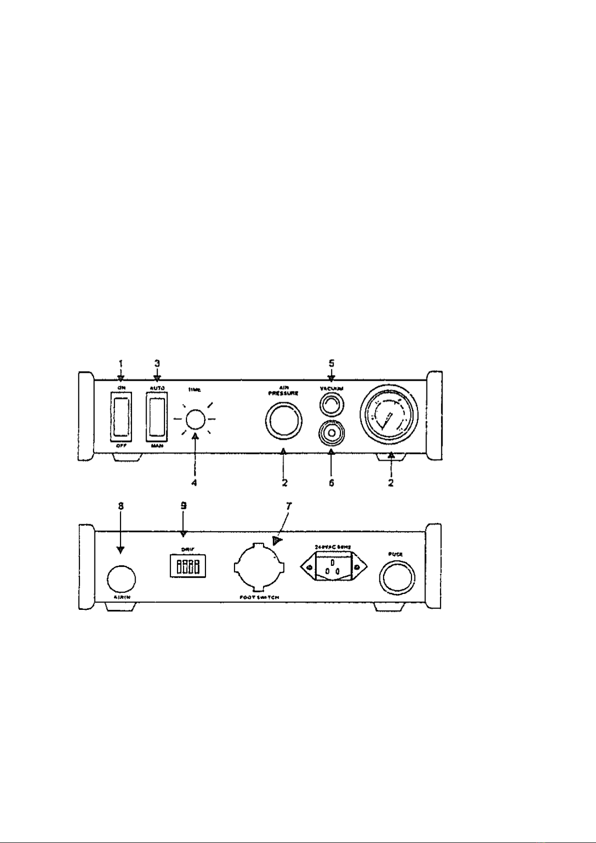
Dotting range regulated..................................................................................................................................... 6
Dotting regulated....................................................................................................................................... 6
Dotting range regulated............................................................................................................................. 6
Internal air pressure regulated ................................................................................................................... 6
Vacuum control regulated ......................................................................................................................... 6
Setup.......................................................................................................................................................... 7
Operation................................................................................................................................................... 7
Caution .............................................................................................................................................................. 8
Maintenance ...................................................................................................................................................... 8
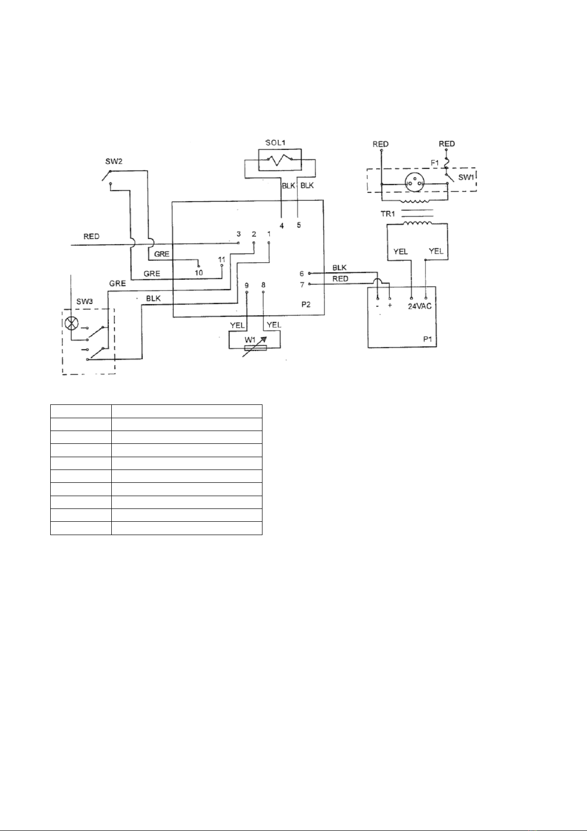
Dispensing Controller Electrical Schematic...................................................................................................... 9
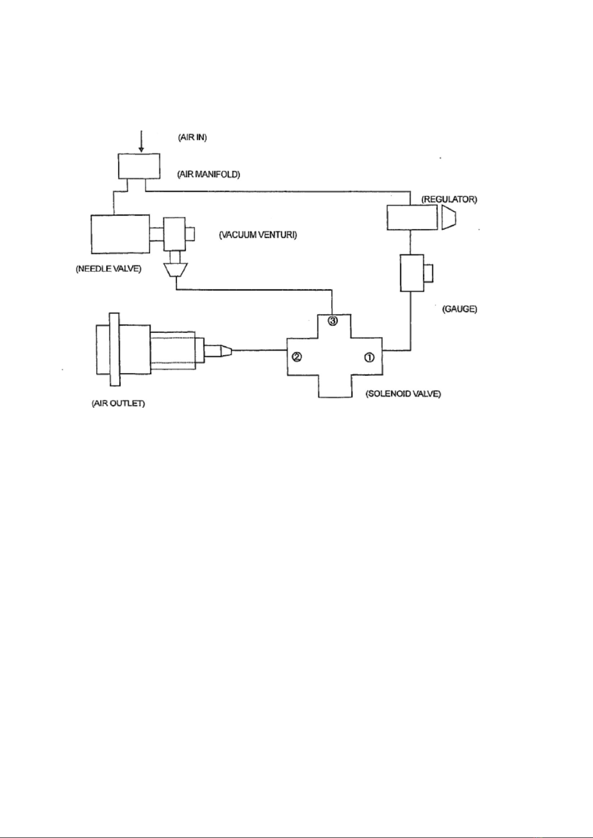
Dispensing Controller Pneumatic System....................................................................................................... 10
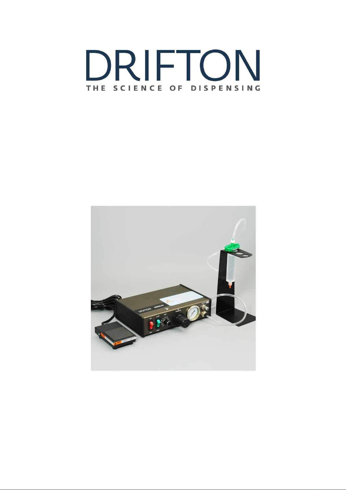
* For your safety, please read this operation manual carefully before operating. And always keep this
manual within reach.
Automatic Liquid Dispenser with time control to push the liquid pneumatically, controlled by timer, to be
sure of the same dispensing drops and dispensing cycle time. Regulate the air pressure with suitable tip on
your equipments with the different liquids such as glues, greases, solder pastes. Applicable for 10 types of
steel tips and 5 types of plastic tips for the customers various needs.