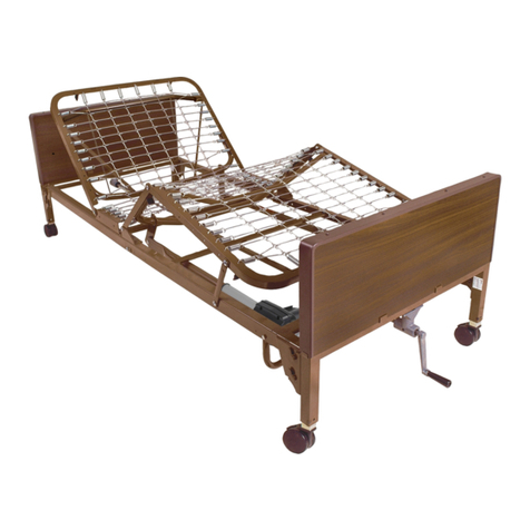
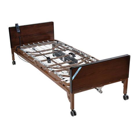
Drive 15005L Assembly instructions

Owner’s Manual and Assembly Instructions
Model # 15005L
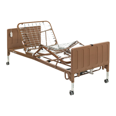
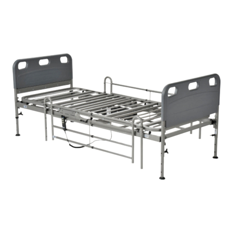
Drive Full Electric Low Height Bed
This manual must be given to the Owner/User
of this bed and should be read carefully before
putting this product into use. Keep manual in
an accessible location for future reference.
Click here to view detailed product information and pricing. Call 800-397-5899 to order today!

TABLE OF CONTENTS
Packaging and Handling........................................................................................................................ 1
Unpacking .......................................................................................................................................... 1
Inspection........................................................................................................................................... 1
Storage .............................................................................................................................................. 1
Assembly Instructions........................................................................................................................... 2
Operation................................................................................................................................................. 6
Hand Control...................................................................................................................................... 6
Caster Lock and Floor Lock Feature.................................................................................................. 6
Bed Rail Installation ............................................................................................................................... 7
Mattress Retainer Adjustment............................................................................................................... 8
Manual Hi/Lo Adjustment Crank ........................................................................................................... 8
Maintenance & Safety Checks............................................................................................................... 9
Warnings ............................................................................................................................................... 10
NOTE: DO NOT operate this product without rst reading and understanding this user manual. Damage or
injury may result from improper use of this product.

1
Packaging / Handling
Unpacking
1. Check cartons for any obvious damage to packaging or contents. If damage is evident,
contact your local Drive Medical dealer/provider.
2. Remove any lose packaging from the cartons.
3. Carefully remove all components from the cartons.
The Two Cartons will contain the following components:
#15215 HeadSpring and Head Board w/casters
#15216 Foot Spring and Foot Board w/ junction box, 3 motor/actuators,
Hand Pendant Control, Emergency Crank Handle.
Inspection
1. Examine each component carefully for damage, scratches, dents or any other visual damage.
2. Carefully remove Tie Wraps holding power cord, hand pendant and drive shaft.
3. Inspect power cord and plug for cuts or damage.
4. Inspect the junction box and motors for damage, loose connections, cuts or damage to the wires.
5. Ensure motor connections to junction box are connected correctly and secure.
Storage
1. If the bed is not assembled immediately, retain cartons and packaging for storage until assembly is
completed.
2. Store the packaged bed in a dry area.
3. DO NOT place other objects on top of the packaged bed cartons.

2
Assembly Instructions
1 Conrm that all parts are present:
A. Foot Spring w/
• 3 motor/actuators
• Junction Box
• Hand Pendant
• Power cord & plug
B. Head Spring
C. Low Height Head Board
D. Low Height Foot Board
E. Hi/Low Drive Shaft
F. Locking Pins (2)
G. Hand Crank
H. Casters (4) – 2 locking, 2 non-locking
I. Head/Foot Pull Tube Transport Straps
A B
I
I
C
D
E
F
G
H
Caution: DO NOT attempt to operate bed controls until completion of assembly as damage to bed
components and/or personal injury may occur.

3
Assembly Instructions (Continued)
2. With the Head and Foot Spring positioned upright, connect Head Spring by aligning with foot spring and
swinging both ends away from each other.
3. Optional: Insert lock pin through connected sleep surface and secure with spring clip.
4. Connect Head Spring and Foot Spring Pull Tube to provide the up/down motion/adjustment of the Head
and Foot Spring Sections:
A. Extend the Head Spring Pull Tube and connect to the Head Spring Lift Arm. Secure in place with the
tethered locking pin and clip
B. Extend the Foot Spring Pull Tube and connect to the Foot Spring Lift Arm.
Secure in place with the tethered locking pin and clip

4
Assembly Instructions Cont.
5. Install the casters by inserting the stem of the
caster into the leg receptacle. It is recommended
to install one locking caster and one non-locking
caster on each bed end. The locking casters
should be installed diagonally from each other.
The 15005L Low Height bed gives you the option of
installing the casters on the inboard non adjustable
legs or the outboard adjustable legs. To achieve
the full low height feature, install the casters on the
inboard non-adjustable legs.
6. Carefully lower the bed frame at onto the oor. Attach the Head
and Foot Boards by tilting the Boards toward your body and aligning
mounting pins located on the Spring Sections with the Hooks on the
Head/Foot Boards.
NOTE: The Head Board is taller than the Foot Board, however, they
are interchangeable with each other.
7. Assemble Hi/Lo Drive Shaft and adjust to the proper length so it will
t between the Head Board drive pin and Hi/Lo Motor drive pin at the
foot end.
• Lift the Head Spring and install the foot end of the Hi/Lo Drive Shaft to the Hi/Lo Motor drive pin, then
install head end of the Hi/Lo Drive Shaft to the Head Board drive pin.
• Hi/Lo Drive Shaft is spring loaded so it will t securely between these two points.
• Adjust length of Hi/Lo Drive Shaft if it is too long or too short.
StemLeg Receptacle

5
Assembly Instructions Cont.
8. Release the spring loaded shaft on
the hi/low motor and insert the shaft
into the gear box on the footboard.
9. Make sure the slot on the spring
loaded shaft engages the roll pin on
the gear box.
10. Raise the Head Spring and Foot Spring to release tension between the springs and connect Head and
Foot spring fabric by squeezing together and attaching with spring links.

6
Operation
Hand Control
The Model #15005L Low Height Bed comes with a 3 Function hand held Pendant.
• Top Buttons control raising and lowering the Head Section;
• Middle Buttons control raising and lowering the Foot Section;
• Lower Buttons control raising and lowering the entire bed.
Caster Lock and Floor Lock Feature
When the bed is in its lowest height position, the Casters will come in contact with the oor and
the bed will roll freely. Engaging the Caster Locks will help hold the bed in place.
When the bed height is raised, the legs will come in contact with the oor and the casters will be raised off the
oor providing a stable base for the bed frame.

7
Bed Rail Installation
The Deck Frame contains labels that provide the location for installing Half Rails and Full Rails.
• On the Head Section and Foot Sections, a Label will indicate the notch location for alignment of the Full
Rail Cross Brace that must be positioned in between the two black springs. A second Label will indicate
alignment for the Half Rail clamp to be positioned with the Black Spring centered between the clamp.
Half Rails Full Rails

8
Mattress Retainer Adjustment
Manual Hi/Lo Adjustment Crank
Before a mattress is laid on the bed, ip up the mattress guard to reduce the movement of the mattress.
In the event of a loss of power or Hi/Lo motor malfunction; the Hi/Lo feature can be manually adjusted using
the Hand Crank. The Hand Crank can be operated in two locations: directly into the Head or Foot board
gear box or from the top of the Head or Foot Board access port.
WARNING: Manual Hi/Lo Adjustment Crank MUST BE REMOVED before the bed is used. Failure to remove
the crank may cause damage to the bed and/or personal injury to those in the room.

9
Drive recommends the following maintenance and cleaning procedures be conducted between users.
ELECTRONICS
• Check all controls to make sure all functions work properly.
• Foot control
• Head control
• Hi/Lo
• Check all cables for damaged or frayed wires.
• Power cord
• Pendant cord
• Check to make sure all plugs are fully inserted or attached.
• Check 9V battery on motor and replace annually.
BED FRAME & SLEEPING SURFACE
• Visually check all welds.
• Head section
• Foot section
• Main Frame
• Check joints between sleeping surface sections for loose fasteners.
CLEANING
• If possible, remove patient/resident before cleaning bed.
• Prior to cleaning unplug power supply cord
• Ensure all electrical parts (motors, control boxes, wires and pendant) are not broken. Ensure that NO liquids enter electrical
components.
• The metal parts of the bed are covered with a powder coating. Clean all coated parts with mild detergent and warm water.
• Raise head and foot sections of the bed to remove dust from frame.
• Remove mattress and clean mattress deck.
• Remove all gross/solid contaminants, then wash and sanitize all components. DO NOT submerge the bed frame or electrical
components.
• Solvents, alcohol, bleach, caustic agents, high acid or alkaline solutions or petroleum based products should not be used on the
bed.
• Use standard water pressure. DO NOT power wash or steam clean any parts.
• Rinse completely with water (Maximum temperature 110oF or 43oC). Do not rinse with cold water.
• Ensure all parts are dry before using or storing.
NOTE: This bed is NOT compatible with wash down tunnels.
LUBRICATION & MECHANICAL
• Lightly grease all actuator screw threads with white lithium grease.
• Lubricate all caster roller and swivel bearings with light machine oil.
• Check all bolts and tighten as needed.
WARRANTY
• Lifetime warranty on welds.
• 5 year warranty on frame.
• 5 year warranty on motor.
• 1 year warranty on all other parts and components.
During the warranty period, defective items will be repaired or replaced at Drive’s option at no charge.
Maintenance & Safety Checks

10
WARNINGS
GENERAL WARNINGS
DO NOT use this product or any available optional equipment without rst completely reading and understand-
ing these instructions and any additional instructional material such as owner’s manuals, service manuals or in-
struction sheets supplied with this product or optional equipment. If you are unable to understand the warnings,
cautions or instructions, contact a healthcare professional, dealer or technical personnel before attempting to
use this equipment - otherwise, injury or damage may occur.
Read all the instructions before using the bed.
Refer to the owner’s manuals for beds and rails for additional product and safety information.
After any adjustments, repair or service and before use, make sure all attaching hardware is tightened se-
curely.
After the bed has been assembled, always test to make sure that all sections of the bed are properly and se-
curely in place before using.
ALWAYS use caster locks except when moving the bed.
Body weight should be evenly distributed over the surface of the bed. DO NOT lay, sit or lean in such a way
that your entire body weight is placed only on raised head or foot sections of the bed. This includes when as-
sisting the user in repositioning or transferring in or out of bed.
Check all parts for shipping damage and test before using. In case of damage, DO NOT use. Contact a quali-
ed technician for further instruction.
Close supervision is necessary when this bed is used by or near children or people with disabilities.
DO NOT let any individual underneath the bed or in between the raised bed frame components at anytime.
DO NOT permit more than one person on/in the bed at any time.
DO NOT use outdoors.
DO NOT use this product or any available optional equipment without rst completely reading and understand-
ing these instructions and any additional instructional material such as owner’s manuals, service manuals or in-
struction sheets supplied with this product or optional equipment. If you are unable to understand the warnings,
cautions or instructions, contact a healthcare professional, dealer or technical personnel before attempting to
use this equipment - otherwise, injury or damage may occur.
For Dealers Only - Set-up and Assembly Instructions are in the front of this manual. These procedures must be
performed by a qualied technicians only.

11
WARNINGS
The March 2006 version of the FDA’s bed safety guidelines are published by Hospital Bed Safety Workgroup.
The latest revision of this document is available at http://www.fda.gov.
If the unit is not working properly, call a qualied technician to examine the unit and repair it.
Drive Medical products are specically designed and manufactured for use in conjunction with Drive Medical
accessories. Accessories designed by other manufacturers have not been tested by Drive Medical and are not
recommended for use with Drive Medical products.
Keep all moving parts, including the main frame, mattress deck (head and foot springs/sections) and all drive
shafts free of obstruction (i.e. blankets/sheets, heating blankets/pads, tubing, wiring, etc. and other types of
products using electric cords which may get tangled around the bed, side rails or legs) during operation of the
bed.
Keep the product a minimum of 12 inches away from any direct heat source.
Make sure head and foot springs/sections are connected securely to the universal bed ends before use.
Physically challenged individuals who cannot prevent themselves from rolling/climbing out of the this bed may
require alternative safe means of restraint.
Procedures other than those described in this manual must be performed by a qualied technician.
Risk of injury to persons - DO NOT place video equipment such as televisions or computer monitors on bed.
NEVER allow patients to use trapeze or traction units as a total individual weight support.
Trapeze units are to be used only for assisting the patient in repositioning or transferring into or out of bed.
Trapeze units must be positioned on a universal bed end as near as possible to the center point of the bed
end.
The bed is not designed to be used as a patient transport. When transporting a patient, use an approved pa-
tient transport. Otherwise, injury or damage may result.
The bed may be equipped with locking casters. When transferring into or out of the bed, always lock the lock-
ing caster(s). Inspect for correct locking action on caster locks before using bed. Even with casters properly
locked, some ooring surfaces such as tile or wood, will allow the bed to move under some conditions. Use on
surfaces such as these must be evaluated by the care provider.
The initial set up of this bed must be performed by a qualied technician.

12
WARNINGS
The total weight limit of the Drive Medical 36 inch (91.4cm) wide Manual/Semi-Electric/Full Electric bed is 450
pounds (204 kg) which includes the weight of the occupant, all accessories such as mattress, side/assist rails,
trapeze, any personal effects, etc.
Example: If total weight of mattress and all accessories is 100 lbs, then total occupant weight can be no more
than 350 lbs.
Use this bed only for its intended use as described in these instructions. DO NOT use attachments not recom-
mended by the manufacturer.
After raising/lowering the head/foot end of the bed, check the distance between the bottom of the bed rail and
the mattress. If there is excessive distance between the bottom of the bed rail and the mattress in which indi-
viduals may become entangled, adjust the height of the bed rail (if applicable), or provide alternative means of
patient protection.
Once patient assessment concludes that the patient’s condition increases the chance of entrapment, the bed
MUST be in the at position when left unattended.
Proper patient assessment and monitoring, and proper maintenance and use of equipment is required to
reduce the risk of entrapment. Variations in bed rail dimensions, and mattress thickness, size or density could
increase the risk of entrapment. Visit the FDA website at http://www.fda.gov to learn about the risks of entrap-
ment.
Replacement mattresses and bed side rails with dimensions different than the original equipment supplied or
specied by the bed frame manufacturer are not interchangeable. Variations in bed side rail design, width and
thickness or rmness of the mattress could cause/contribute to entrapment. Use only authorized Drive Medical
replacement parts and/or accessories otherwise the warranty is void. Drive Medical will not be responsible for
any damage or injury that may result.
To reduce the risk of entrapment make certain that the bed rail cross braces DO NOT exceed the width of the
mattress. Mattress MUST t bed frame and side rails snugly to reduce the risk of entrapment.
When operating this bed, ALWAYS ensure that the individual utilizing the bed is positioned properly within the
connes of the bed. DO NOT let any extremities protrude over the side or between the bed rails when perform-
ing these functions.
Drive Medical recommends that the mattress be centered on the bed frame. Otherwise, individuals may be-
come entangled between the bed rail and the bed frame.
Mattress MUST t bed frame and assist rails snugly to reduce the risk of entrapment.
SAVE THESE INSTRUCTIONS
NOTE: Updated versions of this manual are available on www.Drive Medical.com.

13
BED RAIL WARNINGS
Although bed rails are not rated to any specic weight limitation, the bed rails may become deformed or broken
if excessive side pressure is exerted on the bed rails. The bed rail is not an assist rail for getting into or out of
bed. DO NOT use the bed rails as push handles when moving the bed.
Always test to make sure that the side rails are properly and securely in place before using the bed.
DO NOT install the optional bed rails without reading and understanding all of the instructions in the instruction
sheet that accompanies the bed rail kit.
DO NOT use the side rails as push handles for moving the bed.
These bed rails are intended to prevent an individual from inadvertently rolling out of bed. DO NOT use for
restraint purposes.
When used with a manual/electrical bed, the bed rails DO NOT fall under any weight limitations. Bed rails can
be deformed or broken if excessive side pressure is exerted on the bed rails. These bed rails are used for
the purpose of preventing an individual from inadvertently rolling out of bed. The bed rails are NOT intended
nor may be used for restraint purposes. If an individual is capable of injuring himself/herself, a physician or a
healthcare professional should be consulted for alternative means of safe restraint.
ELECTRICAL WARNINGS
A safety feature of this product includes protection against overheating caused by excessive or extended
periods of operation. Depending on the duration, this includes multiple or repeated adjustments or the use of
multiple functions at one time. To ensure trouble free operation, always allow a slight pause between multiple
adjustments and avoid pressing more than one function button at a time. If thermal protection activation should
occur, the bed will not respond to pendant commands. Given this situation, release the pendant button and
allow the bed unit to sit for several minutes. This will allow the protection function time to reset and restore bed
function. Depending on severity of the initial overheating, this could take up to 30 minutes.
Allow a slight pause between adjustments and avoid pressing multiple buttons at the same time. If pendant
buttons are depressed too rapidly or multiple buttons are pressed at the same time, the desired feature may
not activate. Simply release the pendant button, permit a slight pause and then activate the next operation.
ALWAYS remove manual crank(s) before performing electronic functions. Otherwise, the crank(s) will turn
when the motor is on and could cause personal injury or damage to the bed.
Always unplug the bed from the electrical outlet before cleaning.
DO NOT open assemblies such as the motors, pendant, junction boxes or gear boxes. No user serviceable
parts are inside. Only qualied technicians are permitted to repair these parts. If unqualied individuals perform
any work on these beds, the warranty is void.
WARNINGS

14
WARNINGS
DO NOT place pendant under or between objects. This may unintentionally press the buttons and may cause
injury or damage.
Electronic equipment may be inuenced by Radio Frequency Interference (RFI). Caution should be exer-
cised with regard to the use of portable communications equipment in the area around such equipment. If RFI
causes erratic behavior, unplug the electric bed IMMEDIATELY. Leave unplugged while transmission is in
progress.
Ensure all cables and cords are routed such that they will not become entangled or pinched. Otherwise dam-
age or injury may result.
If a button on the pendant sticks or does not release and/or one of the functions will not stop moving. Unplug
the power cord from the electrical supply outlet and take the bed out of service for repair.
If a liquid is spilled in or around the electric bed, unplug the electric bed before cleaning. Clean up the spill and
allow the electric bed or the area around the electric bed to dry thoroughly before using the electric controls
again.
Inspect the covering of the bed’s control panel and the patient control panel to assure that the covering is not
cracked or damaged.
Keep all electrical cords away from heated or hot surfaces.
Keep the cord away from heated surfaces.
NEVER operate if the unit has a damaged cord or plug. If it is not working properly, call a qualied technician
for examination and repair.
NEVER operate this bed if it has a damaged cord or plug, if it is not working properly, if it has been dropped,
damaged, or dropped into water. Return the bed to a service center for examination and repair.
On Full Electric beds, the Hi/Lo crank MUST be removed before the bed is used. Failure to remove the crank
may cause damage or personal injury.
Refer servicing to qualied personnel only. Grounding reliability depends upon a properly grounded wall outlet.
The pendant and power cords must be routed and secured properly to ensure that the cords DO NOT become
entangled, pinched and/or severed during operation of the electric bed.
Unplug from the outlet before servicing.
Unplug the power cord from its power source before performing any maintenance on the manual/electric bed.
DO NOT unplug the power cord from the junction box. Damage to cord will result.
Use caution when disconnecting the pendant. DO NOT press pendant buttons.

15
When bed is not to be used for an extended period, unplug electric bed from the wall outlet.
When using an extension cord, use only a three wire extension cord having at least 16 AWG (American Wire
Gauge) wire and the same or higher electrical rating as the device being connected. Use of improper extension
cord could result in a risk of re and electric shock. Three to two prong adapters should not be used. Use of
three to two prong adapters can result in improper grounding and present a shock hazard to the user.
When using nasal or masked type oxygen administering equipment, the oxygen or air tubing MUST be routed
and secured properly to ensure that the tubing does not become entangled and/or severed during normal op-
eration of the bed.
DO NOT use near explosive gases.
Possible re hazard when used with oxygen administering equipment other than nasal or masked type.
Use masked or nasal type oxygen administering equipment only in conjunction with this bed. The use of ANY
other type of oxygen administering equipment can result in a re hazard.
WARNINGS

Notes:


99 Seaview Boulevard
Port Washington, NY 11050
Phone: 516-998-4600
Toll Free: 877.224.0946
Fax: 516.998.4601
www.drivemedical.com
REV1.5.27.15
Table of contents
Other Drive Medical Equipment manuals
Drive
Drive Delta 1000 User manual

Drive
Drive Bellavita handset Operating instructions

Drive
Drive 13605 Installation instructions

Drive
Drive CE 1035 FP User manual

Drive
Drive MSS Tilt & Recline User manual

Drive
Drive RTLAGF-900 User manual

Drive
Drive M-Rail User manual

Drive
Drive VacuMax 18610 Manual

Drive
Drive Gravity 6 User manual

Drive
Drive RTL12087 User manual

Drive
Drive FC 8050 User manual

Drive
Drive 13033 User manual

Drive
Drive Premium Guard Gel Overlay User manual

Drive
Drive inspired BCWL-7210S User manual

Drive
Drive 11120SV-1 User manual

Drive
Drive AGF-5X User manual

Drive
Drive TSE 120 User manual

Drive
Drive 13069 User manual

Drive
Drive 14508 User manual

Drive
Drive 16500BV User manual