Druck PV 62XG User manual


[EN] English - K0458 Revision B Quick Reference i
A1.1
PV 621G: Pneumatic pressure station (Figure A2.1)
-950 mbar to 20 bar (-13.5 to 300 psi)
PV 622G: Pneumatic pressure station (Figure A2.2)
-950 mbar to 100 bar (-13.5 to 1500 psi)
PV 623G: Hydraulic pressure station (Figure A2.3)
0 to 1000 bar (0 to 15000 psi)
A1.2 PV 62XG + DPI 620G + PM 620
Recommended pressure modules (PM 620) *
(Figure B1/B2)
PV 621G models 25mbar to 20 bar
(0.36 to 300 psi)
PV 622G models 25 mbar to 100 bar
(0.36 to 1500 psi)
PV 623G models 70 to 1000 bar
(1000 to 15000 psi)
* Caution: To prevent damage to the PM 620 module, only
use it within the specified pressure limit on the label.
A1.3 PV 62XG pressure relief valves (PRV)
(Recommended options)
Parts: IO620-PRV-P1 to P5 (Pneumatic)
PV 621G models 1 to 30 bar
(14.5 to 435 psi)
PV 622G models 1 to 100 bar
(14.5 to 1500 psi)
Parts: IO620-PRV-H1 to H5 (Hydraulic)
PV 623G models 50 to 1000 bar
(725 to 15000 psi)
Note: = See figure, table, or section.

ii Quick Reference K0458 Revision B - [EN] English
A2.1 PV 621G A2.2 PV 622G A2.3 PV 623G
A3 PV 62XG:
1
2
3
4
6
7
8
11
13
12
1
2
3
4
5
7
6
9
11
13
12
7
1
6
2
3
4
9
13
10
S5.1
222
1 2
4
NPTa.
c. (G)/BSPP
P 100 bar
3
b. (G)/BSPP

[EN] English - K0458 Revision B Quick Reference iii
A4 PV 623G: A5 PV 622G, PV 623G
B1 PM 620:
B2 PV 62XG + DPI 620G + PM 620
S3.1
1
2
23
5
+
4
S3.3
A3
1
A1.2
1a
1
3
4
2

iv Quick Reference K0458 Revision B - [EN] English

[EN] English - K0458 Revision B Quick Reference 1
Quick Reference
General warnings
WARNING
• It is dangerous to ignore the specified limits for the instrument or to use the instrument
when it is not in its normal condition. Use the applicable protection and obey all safety
precautions.
• Do not use the instrument in locations with explosive gas, vapour or dust. There is a risk of
an explosion.
Pressure warnings
• It is dangerous to attach an external source of pressure to a PV 62XG series pressure
station. Use only the internal mechanisms to set and control the pressure in the pressure
station.
• Some liquid and gas mixtures are dangerous. This includes mixtures that occur because of
contamination. Make sure that the equipment is safe to use with the necessary media.
• Pressurized gases and fluids are dangerous. Before you attach or disconnect pressure
equipment, safely release all the pressure.
• To prevent a dangerous release of pressure, make sure that all the related pipes, hoses and
equipment have the correct pressure rating, are safe to use and are correctly attached.
• For the PV 623G ensure that the system is bled of excess air before operation. (If the item
under test has a large volume, pre-fill with the pressure fluid to ensure that trapped air is
kept to a minimum).
Electrical warnings
If you use the DPI 620G calibrator with your pressure station, these warnings are also applicable:
• To prevent electrical shocks or damage to the instrument, do not connect more than 30V
between the terminals, or between the terminals and the ground (earth).
• This instrument uses a Lithium-Polymer (Li-Polymer) battery pack. To prevent an explosion
or fire, do not short circuit, do not disassemble, keep it safe from damage.
• To prevent an explosion or fire, use only the Druck specified battery, power supply and
battery charger.
Cautions
•To prevent damage to the PM 620 module, only use it within the specified pressure limit on
the label.
• To prevent damage to the instrument, do not let dirt get into the pressure mechanism.
Clean the equipment before you attach it.
• Before you start an operation or procedure in this publication, make sure that you have the
necessary skills (if necessary, with qualifications from an approved training
establishment). Follow good engineering practice at all times.

2 Quick Reference K0458 Revision B - [EN] English
S1 PV 621G models: Start operations
WARNING
Pressurized gases and fluids are dangerous. Before connecting or disconnecting pressure equipment,
safely release all the pressure (Ref: K0457, 2.2, Release the pressure).
Caution: To prevent damage to the pressure station, do not let dirt get into the pressure mechanism.
Before connecting equipment, make sure it is clean or use the applicable dirt trap.
S1.1 Release the pressure/Attach the device under test
S1.2 Vacuum OR pressure operation
Step Procedure
1. Open the pressure release valve (one turn) (Ref: Item4).
2. Use the applicable adaptor to attach the device, (Ref: figure A3, Item 2).
Step Procedure (Vacuum)
1. Set to vacuum operation (-) (Ref: Item 11).
2. Turn the volume adjuster to mid-range or fully clockwise (Ref: Item 8).
3. Seal the system (Ref: Item 4).
4. Set the approximate vacuum with the pump (Ref: Item 12).
5. Adjust the vacuum with the volume adjuster (Ref: Item 8).
Step Procedure (Pressure)
1. Set to pressure operation (+) (Ref: Item 11).
2. Turn the volume adjuster to mid-range (Ref: Item 8).
3. Seal the system (Ref: Item 4).
4. Set the approximate pressure with the pump (Ref: Item 12).
5. Adjust the pressure with the volume adjuster (Ref: Item 8).
A2.1 (Front cover)

[EN] English - K0458 Revision B Quick Reference 3
S2 PV 622G models: Start operations
WARNING
Pressurized gases and fluids are dangerous. Before connecting or disconnecting pressure equipment,
safely release all the pressure (Ref: K0457, 3.2, Release the pressure).
Caution: To prevent damage to the pressure station, do not let dirt get into the pressure mechanism.
Before connecting equipment, make sure it is clean or use the applicable dirt trap.
S2.1 Release the pressure/Attach the device under test
S2.2 Vacuum OR pressure operation
Step Procedure
1. Fully open the refill valve
2. Open the pressure release valve (one turn) (Ref: Item 4)
3. Use the applicable adaptor to attach the device, (Ref: figure A3, Item 2)
Step Procedure (Vacuum)
1. Set to vacuum operation (-) (Ref: Item 11).
2. Open the refill valve (1 turn) (Ref: Item 5).
3. Wind the volume adjuster to mid-range or fully clockwise (Ref: Item 9).
4. Seal the system (Ref: Item 4).
5. Set the approximate vacuum with the pump (Ref: Item 12).
6. Adjust the vacuum with the volume adjuster (Ref: Item 9).
Step Procedure (Pressure)
1. Set to pressure operation (+) (Ref: Item 11).
2. Turn the volume adjuster to mid-range (Ref: Item 9).
3. Seal the system (Ref: Item 4).
4. Use the pump to set a pressure up to ≈20 bar (300 psi) (Ref: Item 12).
5. Open the refill valve (1 turn) (Ref: Item 5).
6. Increase or decrease the pressure with the volume adjuster (Ref: Item 9).
7. If increasing pressure the limit of travel is reached, close the refill valve (Ref: Item 5).
8. Wind the volume adjuster fully counterclockwise. (Ref: Item 9).There is no change in pressure.
9. Refill the pressure mechanism with the pump (≈15 cycles) (Ref: Item 12).
10. Wind the volume adjuster clockwise until the pressure starts to increase (Ref: Item 9).
11. Continue to do steps 7 to 10 until you get the necessary pressure.
A2.2 (Front cover)

4 Quick Reference K0458 Revision B - [EN] English
S3 PV 623G models: Start operations
WARNING
Pressurized gases and fluids are dangerous. Before connecting or disconnecting pressure equipment,
safely release all the pressure (Ref: K0457, 4.3, Release the pressure).
Caution: To prevent damage to the pressure station, do not let dirt get into the pressure mechanism.
Before connecting equipment, make sure it is clean.
S3.1 Release the pressure/Attach the device under test
Note: Fill the reservoir before attaching the device. (Ref: figure A4).
S3.2 Filling, priming and generating pressure (Ref: Figure A4). Fill the reservoir
using the procedure that follows:
Caution: Ice in the pressure mechanism can cause damage. If the temperature is less than 4°C
(39°F), drain all water from the PV 623G pressure station.
When using the PV 623G pressure station for the first time, fill the reservoir with the correct hydraulic
fluid (Ref: K0457 Table 7.1 General specification PV 62XG). Fill and prime the pressure station.
S3.3 Filling and Priming
Step Procedure
1. Open the refill valve fully counter-clockwise (Ref Item 10).
2. Open the pressure release valve counter-clockwise (1 turn) (Ref Item 4).
3. Use the applicable adaptor to attach the device, (Ref: figure A3, Item 2).
Step Procedure
1. If new, remove the red plastic blanking cover from the Test port.
2. Turn the Refill valve fully counter-clockwise.
3. Turn the Volume adjuster fully clockwise.
4. Turn the Release Valve Stem fully counter-clockwise.
5. Remove the Priming pump piston/Release valve stem assembly
6. Fill the reservoir with the recommended fluid, (Ref: K0457 Table 7.1 General
specification PV 62XG) 25mm approx from the top.
7. Re-fit the Priming pump piston/Release valve stem assembly
8. Turn the Release Valve Stem fully clockwise.
9. Turn the Refill valve fully clockwise, until finger tight.
10. Turn the Volume adjuster fully counter-clockwise.
11. Turn the Volume adjuster 5 turns clockwise.
12. Operate the Priming pump until the air is expelled and fluid is visible at the Test port.
13. Fit the “Item under test” to the Test port use the existing adaptor or the applicable AMC
adaptor and applicable seals.
14. Operate the Priming pump and prime the system to a maximum pressure of 10 bar.
A2.3 (Front cover)

[EN] English - K0458 Revision B Quick Reference 5
1 Overview
There are three pressure stations in the PV 62XG series:
• Two pneumatic pressure stations to give you accurate and controlled pressure and vacuum
conditions:
PV 621G: -950 mbar to 20 bar (-13.5 to 300 psi) version
PV 622G: -950 mbar to 100 bar (-13.5 to 1500 psi) version.
• One hydraulic pressure station to give you accurate and controlled hydraulic pressure conditions:
PV 623G: 0 to 1000 bar (15000 psi).
1.1 Other module options
The pressure stations are part of a set of hand-held modules that can produce a wide range of calibrator
functions.
DPI 620G Pressure calibrator:
You can use the pressure stations on their own or you can attach the DPI 620G calibrator and a PM 620
module to make a fully integrated pressure calibrator instrument.
Advanced modular calibrator, DPI 620G:
Optional item. This is a battery-powered instrument for electrical measure and source operations and
HART® communications. It also supplies the power and user interface functions for all the add-on
modules. You can use the touch-screen to display up to six different parameters. Refer to user manual
- K0541.
Pressure modules, PM 620:
Optional item. These modules attach to a pressure station (PV 62XG) to give the DPI 620G
calibrator the necessary pressure measurement functionality. They are fully interchangeable “plug and
play” modules with no initial set-up or user calibration.
15. Turn the Volume adjuster clockwise, until the required pressure is indicated.
16. Turn the refill valve fully counter-clockwise to allow full pressure control.
Step Procedure
PV 621G PV 622G PV 623G
Pressure calibrator DPI 620G PM 620

6 Quick Reference K0458 Revision B - [EN] English
2 Standard equipment
These items are part of the standard equipment with a PV 62XG pressure station:
• Removable pressure adaptors (G1/8 and 1/8 NPT).
• PV 623G models only: Refill bottle for hydraulic fluid.
• Safety and quick reference guide.
• CD with the user manual.
3 Safety
Before you use the instrument, make sure that you read and understand all the related data.
This includes: the applicable local safety procedures, the user manual (K0457), and the instructions for
the accessories/options/equipment you are using it with.
Marks and symbols on the instrument
Complies with European
Union directives
Warning - refer to the
manual
Read the manual PRV Pressure relief valve
Do not dispose of this product as household waste. Refer to
Section 6 (Maintenance).
More marks and symbols are specified in the user manual (K0457 -
Druck PV 62XG pneumatic/hydraulic pressure stations)

[EN] English - K0458 Revision B Quick Reference 7
4 Parts
Refer to the figures on the front cover (A2, B1).
4.1 Key to figure A2 (PV 62XG pressure stations)
4.2 Key to figure B1 (PM 620 module) - Optional item
A2 1. Optional accessory: Pressure connection for a pressure relief valve
(PRV); see table A1.3 (front cover). A blanking plug is standard.
2. Test port: Pressure connection (G1/8 or 1/8NPT) to attach the device
under test; see figure A3 (front cover).
3. Pressure and electrical connections for a PM 620 module.
PV 621G/PV 622G models: Seal the pressure connection with a
blanking plug (Part: IO620-BLANK) or a PM 620 module.
PV 623G models only: The pressure connection seals itself.
4.Pneumatic pressure release valve (PV 621G/PV 622G models) or
hydraulic pressure release valve (PV 623G models) to release
pressure in the system.
On PV 623G models, it also gives access to the hydraulic fluid
reservoir; see figure A4 (front cover).
5. PV 622G models only: Pneumatic refill valve. Close it to seal off the
device pressure and refill the pressure mechanism (refer to “Quick
Reference”, S2).
6. Moulded compartment for the DPI 620G calibrator with electrical
connections and a mechanism to hold it in position.
7. Push-button mechanism to release the DPI 620G calibrator.
8. PV 621G models only: Pneumatic volume adjuster
9.PV 622G/PV 623G models only: Volume adjuster wheel with fold-in
handle.
10. PV 623G models only: Hydraulic refill valve. Close it to seal off the
device pressure and refill the pressure mechanism with fluid (refer to
“Quick Reference”, S3).
11. PV 621G/PV 622G models only: Pressure/vacuum selector to set the
pump operation: pressure (+), vacuum (-).
12. PV 621G/PV 622G models only: Pump mechanism
B1 13. Pressure module (PM 620) with a pressure connection, reference port
(a) and a label. The label includes:
Pressure limit. Example: 20 bar g (g: gauge; a: absolute); serial
number (S/N); manufacturer: name, address, website

8 Quick Reference K0458 Revision B - [EN] English
5 Installation
Before starting do the following:
• Read and understand the “Safety” section.
• Do not use damaged equipment.
Note: Use only original parts supplied by the manufacturer.
5.1 External pressure connections
Ref: figure A3 (front cover). Use an applicable method to seal the external pressure connections,
and then tighten to the applicable torque. Maximum torque:
1/8 NPT: 35 Nm (26 lbf.ft)
G1/8: 25 Nm (18.4 lbf.ft)
5.2 Calibrator assembly
Optional item. (DPI 620G/PM 620). See figure B2 (front cover).
Note: To use the DPI 620G calibrator, read the user manuals: K0541 (Druck DPI 620G Advanced
modular calibrator) and K0457 (Druck PV 62XG pneumatic/hydraulic pressure stations).
.
6 Maintenance
Clean the case with a moist, lint-free cloth and a weak detergent. Do not use solvents or abrasive
materials.
Return the instrument to the manufacturer or an approved service agent for all repairs.
Do not dispose of this product as household waste. Use an approved organisation that collects and/or
recycles waste electrical and electronic equipment. For more information, contact one of these:
• Customer service department: Druck.com
• Local government office.
B2 Step Procedure
1. Lower the calibrator into the moulded compartment.
2. Press on the bottom end of the calibrator until it latches in position.
3. Attach a pressure module with the correct range and type.
4. Tighten it until it is hand tight only.

[EN] English - K0458 Revision B Quick Reference 9
7 Specification
Table 1: General specification
Operating temperature -10 to 50°C (14 to 122°F)
Note: PV 623G models only. If the temperature is less than 4°C (39°F),
the instrument must be fully drained and dry.
Storage temperature -20 to 70°C (-4 to 158 °F)
Note: PV 623G models only. If the temperature is less than 4°C (39°F),
the instrument must be fully drained and dry.
Humidity 0 to 90% relative humidity (RH) non-condensing
Shock/Vibration Def Stan 66-31, 8.4 cat III
EMC Electromagnetic compatibility: BS EN 61326-1:2013
Electrical safety Electrical - BS EN 61010-1:2010
Pressure safety Pressure Equipment Directive - Class: Sound Engineering Practice
(SEP)
Approved CE Marked
Hydraulic fluid (PV 623G
models only)
Reservoir capacity: 100 cm³ (6.1 in³)
Fluid type: Demineralised water or a mineral oil (ISO viscosity grade ≤
22)
Power supply None. If you attach a DPI 620G calibrator to make a pressure calibrator,
all the power comes from the DPI 620G calibrator. Refer to user manual
K0541 - Druck DPI 620G Advanced modular calibrator

10 Quick Reference K0458 Revision B - [EN] English

[DE] Deutsch - K0458 Revision B Kurzanleitung 11
Kurzanleitung
Allgemeine Warnungen
WARNUNG
• Arbeiten Sie nur innerhalb der für das Gerät angegebenen Grenzwerte und verwenden Sie nur ein
einsatzbereites Gerät, um Verletzungen oder Beschädigungen des Geräts zu verhindern. Verwenden
Sie geeignete Schutzvorrichtungen und treffen Sie alle erforderlichen Sicherheitsmaßnahmen.
• Betreiben Sie das Gerät auf keinen Fall in Umgebungen mit explosiven Gasen, Dämpfen oder Staub.
In diesen Umgebungen besteht Explosionsgefahr.
Warnungen in Bezug auf das Drucksystem
• Das Anschließen einer externen Druckquelle an eine Druckstation der PV 62XG-Serie ist gefährlich.
Verwenden Sie nur die internen Vorrichtungen, um den Druck in der Druckstation einzustellen und zu
kontrollieren.
• Bestimmte Flüssigkeits- und Gasgemische sind gefährlich. Dazu zählen Gemische, die durch
Verunreinigungen entstehen. Stellen Sie sicher, dass der Betrieb des Geräts mit den erforderlichen
Medien sicher ist.
• Unter Druck stehende Gase und Flüssigkeiten sind gefährlich. Bevor Sie ein Druckgerät anbringen
oder lösen, müssen Sie den gesamten Druck sicher ablassen.
• Um ein schlagartiges Entweichen von Druck zu vermeiden, stellen Sie sicher, dass alle Rohre,
Schläuche und Geräte für den richtigen Nenndruck bemessen sind, der Betrieb der Komponenten
sicher ist und alle Komponenten ordnungsgemäß angebracht sind.
• Stellen Sie bei der PV 623G vor dem Betrieb sicher, dass überschüssige Luft aus dem System
entfernt wurde. (Wenn der Prüfling ein großes Volumen aufweist, füllen Sie das System mit der
Prozessflüssigkeit vor, um den Lufteinschluss auf ein Minimum zu reduzieren).
Warnungen in Bezug auf elektrische Anlagen
Wenn Sie den DPI 620G-Kalibrator mit Ihrer Druckstation verwenden, sind außerdem die folgenden
Warnhinweise zu beachten:
• Legen Sie keine höheren Spannungen als 30 V zwischen den Klemmen bzw. zwischen den Klemmen
und der Masse (Erde) an, um Stromschläge und Beschädigungen des Geräts zu vermeiden.
• Dieses Gerät verwendet eine Lithium-Polymer-Batterie. Um Explosions- und Brandgefahr zu
vermeiden, darf die Batterie nicht kurzgeschlossen, zerlegt oder beschädigt werden.
• Um Explosions- und Brandgefahr zu vermeiden, verwenden Sie nur von Druck zugelassene
Batterien, Netzteile und Batterieladegeräte.
Achtung
•Um Schäden am PM 620-Modul zu vermeiden, halten Sie im Betrieb die auf dem Typenschild
angegebenen Druckgrenzwerte ein.
• Achten Sie darauf, dass keine Verschmutzungen in den Druckmechanismus gelangen, um
Beschädigungen des Geräts zu vermeiden. Reinigen Sie die Ausrüstung, bevor Sie sie anschließen.
• Vergewissern Sie sich, dass Sie über die erforderlichen Fähigkeiten verfügen (ggf. durch eine
Schulung in einer zugelassenen Schulungseinrichtung), bevor Sie in diesem Dokument
beschriebene Vorgänge oder Verfahren durchführen. Halten Sie sich immer an bewährte Verfahren.

12 Kurzanleitung K0458 Revision B - [DE] Deutsch
S1 PV 621G-Modelle: Maßnahmen zur Inbetriebnahme
WARNUNG
Unter Druck stehende Gase und Flüssigkeiten sind gefährlich. Bevor Sie ein Druckgerät anschließen oder
trennen, müssen Sie den gesamten Druck sicher ablassen (siehe K0457, 2.2, Druck ablassen).
Achtung: Achten Sie darauf, dass keine Verschmutzungen in den Druckmechanismus gelangen, um
Beschädigungen der Druckstation zu vermeiden. Vergewissern Sie sich vor dem Anschließen eines Geräts, dass
dieses sauber ist oder verwenden Sie einen geeigneten Schmutzabscheider.
S1.1 Druck ablassen/Prüfling anbringen
S1.2 Vakuum- ODER Druckbetrieb
Schritt Verfahren
1. Öffnen Sie das Überdruckventil (1 Umdrehung) (siehe Punkt 4).
2. Schließen Sie das Gerät über den entsprechenden Adapter an (siehe Abbildung A3, Punkt 2).
Schritt Verfahren (Vakuum)
1. Stellen Sie das Gerät auf Vakuumbetrieb (-) (siehe Punkt 11).
2. Drehen Sie den Volumenregler in die Mittelposition oder bis zum Anschlag im Uhrzeigersinn (siehe Punkt 8).
3. Dichten Sie das System ab (siehe Punkt 4).
4. Stellen Sie das ungefähre Vakuum mit der Pumpe ein (siehe Punkt 12).
5. Passen Sie das Vakuum mit dem Volumenregler an (siehe Punkt 8).
Schritt Verfahren (Druck)
1. Stellen Sie das Gerät auf Druckbetrieb (+) (siehe Punkt 11).
2. Drehen Sie den Volumenregler in die Mittelposition (siehe Punkt 8).
3. Dichten Sie das System ab (siehe Punkt 4).
4. Stellen Sie den ungefähren Druck mit der Pumpe ein (siehe Punkt 12).
5. Passen Sie den Druck mit dem Volumenregler an (siehe Punkt 8).
A2.1 (Deckblatt)

[DE] Deutsch - K0458 Revision B Kurzanleitung 13
S2 PV 622G-Modelle: Maßnahmen zur Inbetriebnahme
WARNUNG
Unter Druck stehende Gase und Flüssigkeiten sind gefährlich. Bevor Sie ein Druckgerät anschließen oder
trennen, müssen Sie den gesamten Druck sicher ablassen (siehe K0457, 3.2, Druck ablassen).
Achtung: Achten Sie darauf, dass keine Verschmutzungen in den Druckmechanismus gelangen, um
Beschädigungen der Druckstation zu vermeiden. Vergewissern Sie sich vor dem Anschließen eines Geräts, dass
dieses sauber ist oder verwenden Sie einen geeigneten Schmutzabscheider.
S2.1 Druck ablassen/Prüfling anbringen
S2.2 Vakuum- ODER Druckbetrieb
Schritt Verfahren
1. Öffnen Sie das Nachfüllventil bis zum Anschlag.
2. Öffnen Sie das Überdruckventil (1 Umdrehung) (siehe Punkt 4).
3. Schließen Sie das Gerät über den entsprechenden Adapter an (siehe Abbildung A3, Punkt 2).
Schritt Verfahren (Vakuum)
1. Stellen Sie das Gerät auf Vakuumbetrieb (-) (siehe Punkt 11).
2. Öffnen Sie das Nachfüllventil (1 Umdrehung) (siehe Punkt 5).
3. Drehen Sie den Volumenregler in die Mittelposition oder bis zum Anschlag im Uhrzeigersinn (siehe Punkt 9).
4. Dichten Sie das System ab (siehe Punkt 4).
5. Stellen Sie das ungefähre Vakuum mit der Pumpe ein (siehe Punkt 12).
6. Passen Sie das Vakuum mit dem Volumenregler an (siehe Punkt 9).
Schritt Verfahren (Druck)
1. Stellen Sie das Gerät auf Druckbetrieb (+) (siehe Punkt 11).
2. Drehen Sie den Volumenregler in die Mittelposition (siehe Punkt 9).
3. Dichten Sie das System ab (siehe Punkt 4).
4. Stellen Sie mit der Pumpe einen Druck von bis zu ≈20 bar (300 psi) ein (siehe Punkt 12).
5. Öffnen Sie das Nachfüllventil (1 Umdrehung) (siehe Punkt 5).
6. Erhöhen oder verringern Sie den Druck mit dem Volumenregler (siehe Punkt 9).
7. Wenn Sie den Druck erhöhen und den Anschlag des Reglers erreicht haben, schließen Sie das
Nachfüllventil (siehe Punkt 5).
8. Drehen Sie den Volumenregler im Uhrzeigersinn bis zum Anschlag (siehe Punkt 9). Der Druck bleibt
unverändert.
9. Füllen Sie den Druckmechanismus mit der Pumpe auf (≈15 Zyklen) (siehe Punkt 12).
10. Drehen Sie dann den Volumenregler im Uhrzeigersinn, bis der Druck ansteigt (siehe Punkt 9).
11. Wiederholen Sie die Schritte 7 bis 10, bis Sie den erforderlichen Druck erreicht haben.
A2.2 (Deckblatt)

14 Kurzanleitung K0458 Revision B - [DE] Deutsch
S3 PV 623G-Modelle: Maßnahmen zur Inbetriebnahme
WARNUNG
Unter Druck stehende Gase und Flüssigkeiten sind gefährlich. Bevor Sie ein Druckgerät anschließen oder
trennen, müssen Sie den gesamten Druck sicher ablassen (siehe K0457, 4.3, Druck ablassen).
Achtung: Achten Sie darauf, dass keine Verschmutzungen in den Druckmechanismus gelangen, um
Beschädigungen der Druckstation zu vermeiden. Vergewissern Sie sich vor dem Anschließen eines Geräts, dass
dieses sauber ist.
S3.1 Druck ablassen/Prüfling anbringen
Hinweis: Füllen Sie den Behälter, bevor Sie das Gerät anbringen (siehe Abbildung A4).
S3.2 Auffüllen, Vorbereitung und Druckerzeugung (siehe Abbildung A4). Füllen Sie den
Behälter mit dem folgenden Verfahren auf:
Achtung: Im Druckmechanismus vorhandenes Eis kann Schäden verursachen. Wenn die Temperatur weniger
als 4°C (39°F) beträgt, lassen Sie das gesamte Wasser aus der PV 623G-Druckstation ab.
Füllen Sie bei der ersten Benutzung der PV623G-Druckstation den Behälter mit der richtigen Hydraulikflüssigkeit
(siehe K0457, Tabelle 7.1, Allgemeine technische Daten PV 62XG). Füllen Sie die Druckstation und bereiten Sie
sie vor.
S3.3 Auffüllen und Vorbereiten
Schritt Verfahren
1. Öffnen Sie das Nachfüllventil vollständig gegen den Uhrzeigersinn (siehe Punkt 10).
2. Öffnen Sie das Überdruckventil gegen den Uhrzeigersinn (1 Umdrehung) (siehe Punkt 4).
3. Schließen Sie das Gerät über den entsprechenden Adapter an (siehe Abbildung A3, Punkt 2).
Schritt Verfahren
1. Entfernen Sie, falls erforderlich, den roten Kunststoff-Blindstopfen vom Prüfanschluss.
2. Drehen Sie das Nachfüllventil gegen den Uhrzeigersinn bis zum Anschlag.
3. Drehen Sie den Volumenregler im Uhrzeigersinn bis zum Anschlag.
4. Drehen Sie den Stößel des Überdruckventils gegen den Uhrzeigersinn bis zum Anschlag.
5. Entfernen Sie die Handpumpenkolben/Überdruckventil-Stößel-Baugruppe.
6. Füllen Sie den Behälter mit der empfohlenen Flüssigkeit (siehe K0457, Tabelle 7.1, Allgemeine
technische Daten PV 62XG) bis zu etwa 25 mm vom oberen Rand.
7.Bringen Sie die Handpumpenkolben/Überdruckventil-Stößel-Baugruppe wieder an.
8. Drehen Sie den Stößel des Überdruckventils im Uhrzeigersinn bis zum Anschlag.
9. Drehen Sie das Nachfüllventil im Uhrzeigersinn handfest bis zum Anschlag.
10. Drehen Sie den Volumenregler gegen den Uhrzeigersinn bis zum Anschlag.
11. Drehen Sie den Volumenregler um 5 Umdrehungen im Uhrzeigersinn.
12. Betätigen Sie die Handpumpe, bis die Luft austritt und am Prüfanschluss Flüssigkeit zu sehen ist.
13. Bringen Sie den Prüfling mit dem vorhandenen Adapter oder dem geeigneten AMC-Adapter und
den entsprechenden Dichtungen am Prüfanschluss an.
14. Betätigen Sie die Handpumpe und beaufschlagen Sie das System maximal mit einem Druck von 10 bar.
15. Drehen Sie dann den Volumenregler im Uhrzeigersinn, bis der erforderliche Druck angezeigt wird.
A2.3 (Deckblatt)
Table of contents
Languages:
Other Druck Test Equipment manuals

Druck
Druck PTC200 User manual

Druck
Druck DPI 620 Genii User manual

Druck
Druck DPI 620 Genii Instruction Manual

Druck
Druck UPS-III User manual

Druck
Druck DPI620 Genii User manual

Druck
Druck UPS-III-IS User manual
Druck
Druck InstruMetrics ADTS542F Setup guide

Druck
Druck TRX User manual

Druck
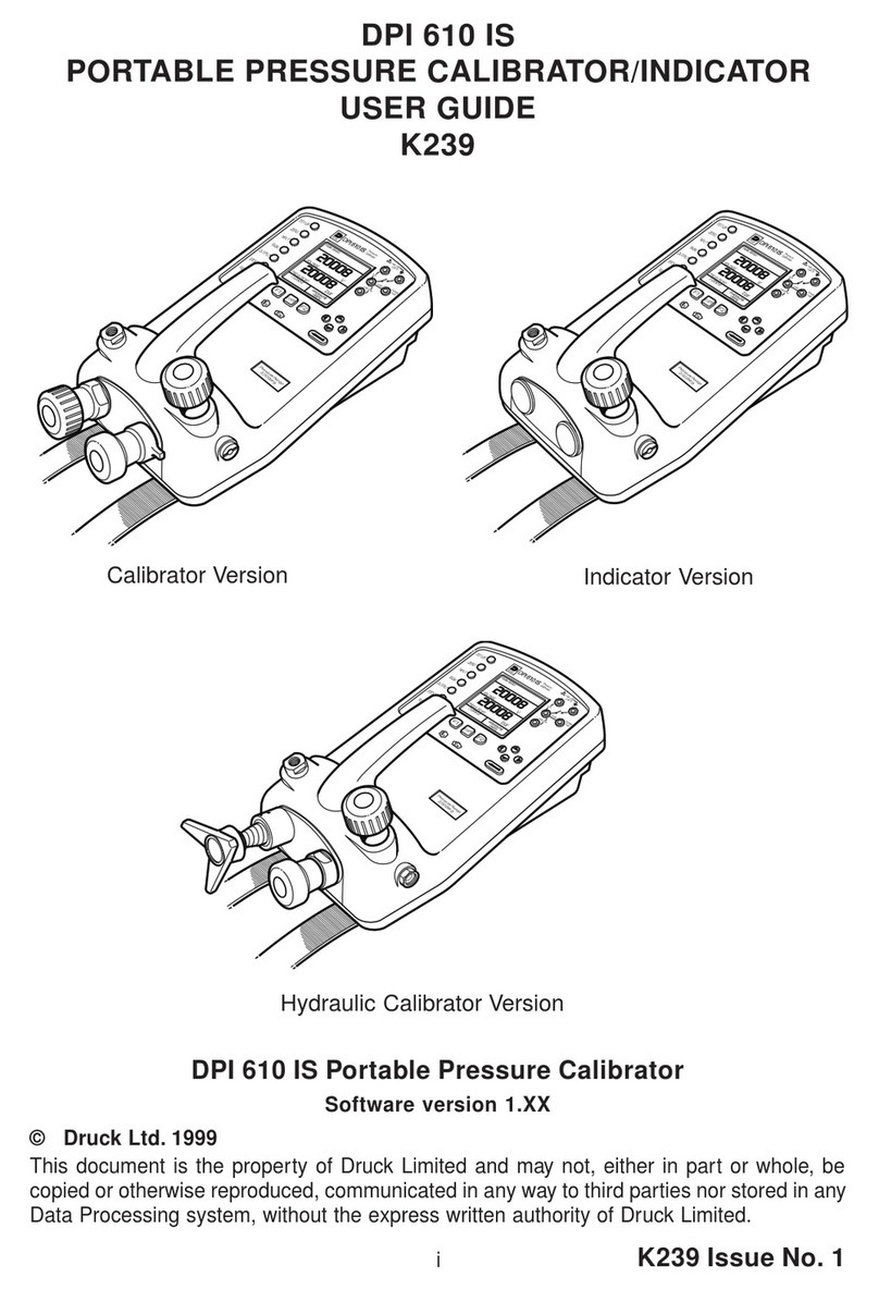
Druck DPI 610 IS User manual

Druck
Druck DPI 610E User manual
Popular Test Equipment manuals by other brands

Hantek
Hantek 2D82Auto manual

Keysight
Keysight 16048D Operation and service manual

Agilent Technologies
Agilent Technologies 3000 Series manual

Astro Pneumatic Tool
Astro Pneumatic Tool 78585 manual

VIAVI Solutions
VIAVI Solutions T-BERD Quick Card User Guide

VOLTCRAFT
VOLTCRAFT 25 04 55 operating instructions