Druck DPI 841 User manual

Druck DPI 841/842
Frequency calibrator and
Frequency loop calibrator
User manual - K395
99 Washington Street
Melrose, MA 02176
Phone 781-665-1400
Toll Free 1-800-517-8431
Visit us at www.TestEquipmentDepot.com

K395 Issue 3
A1
A2 DPI 842
A3
10
1
3
4
2
5
6
7
9
8
A 2
A 3
11
B1
12
14
1513
20
21
22
25
1718
26
19 2716
23
24
B1
Customer service
Visit our web site: www.gesensing.com

[EN] English - 1
K395 Issue 3
Table of Contents
Introduction ......................................................................... 1
Safety ..................................................................................... 1
Marks and symbols on the instrument ................................. 2
To start .................................................................................. 2
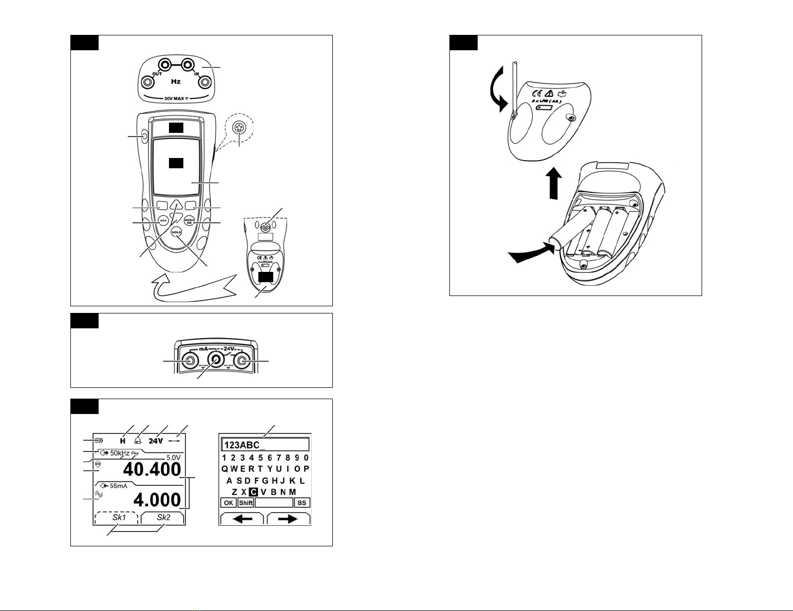
Location of items ............................................................................ 2
Items on the display ...................................................................... 2
Prepare the instrument ................................................................ 2
Power on or off ................................................................................ 3
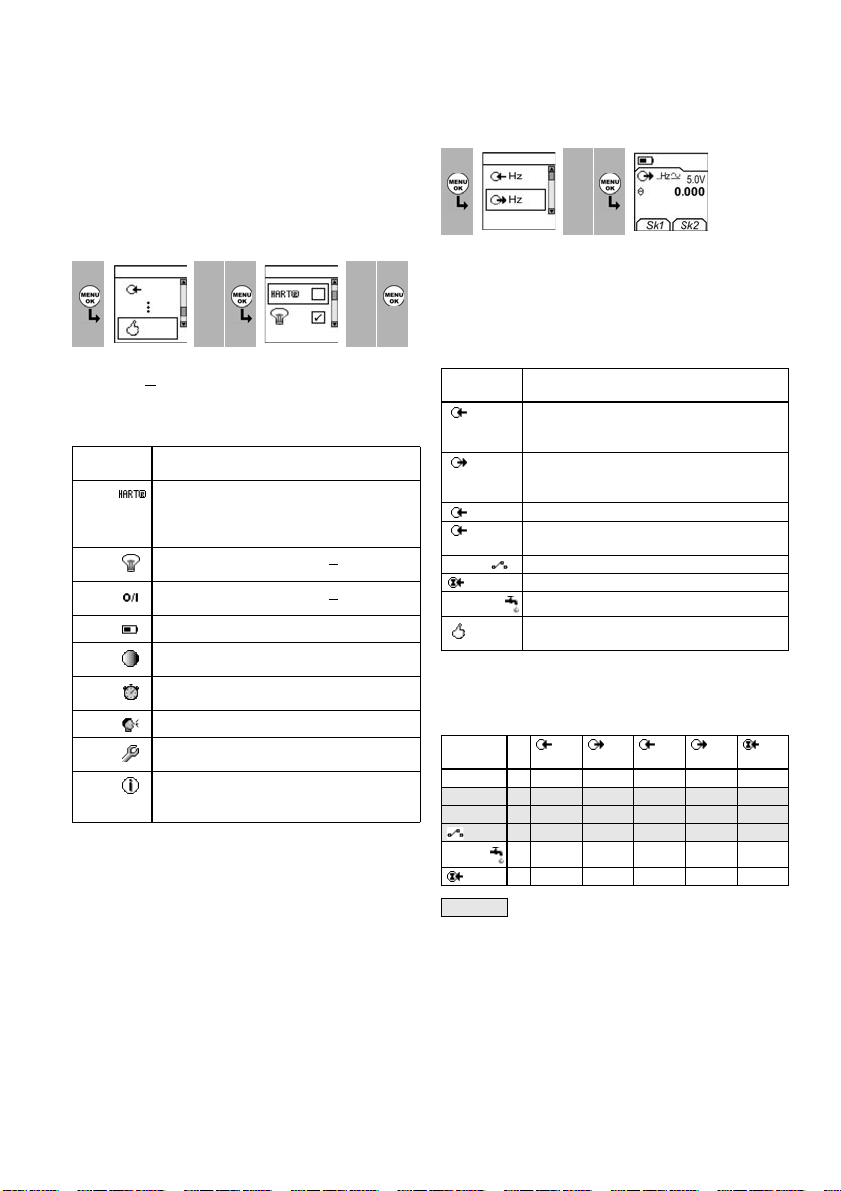
Set up the basic operation ......................................................... 3
Select a task (Measure and/or supply) .................................. 3
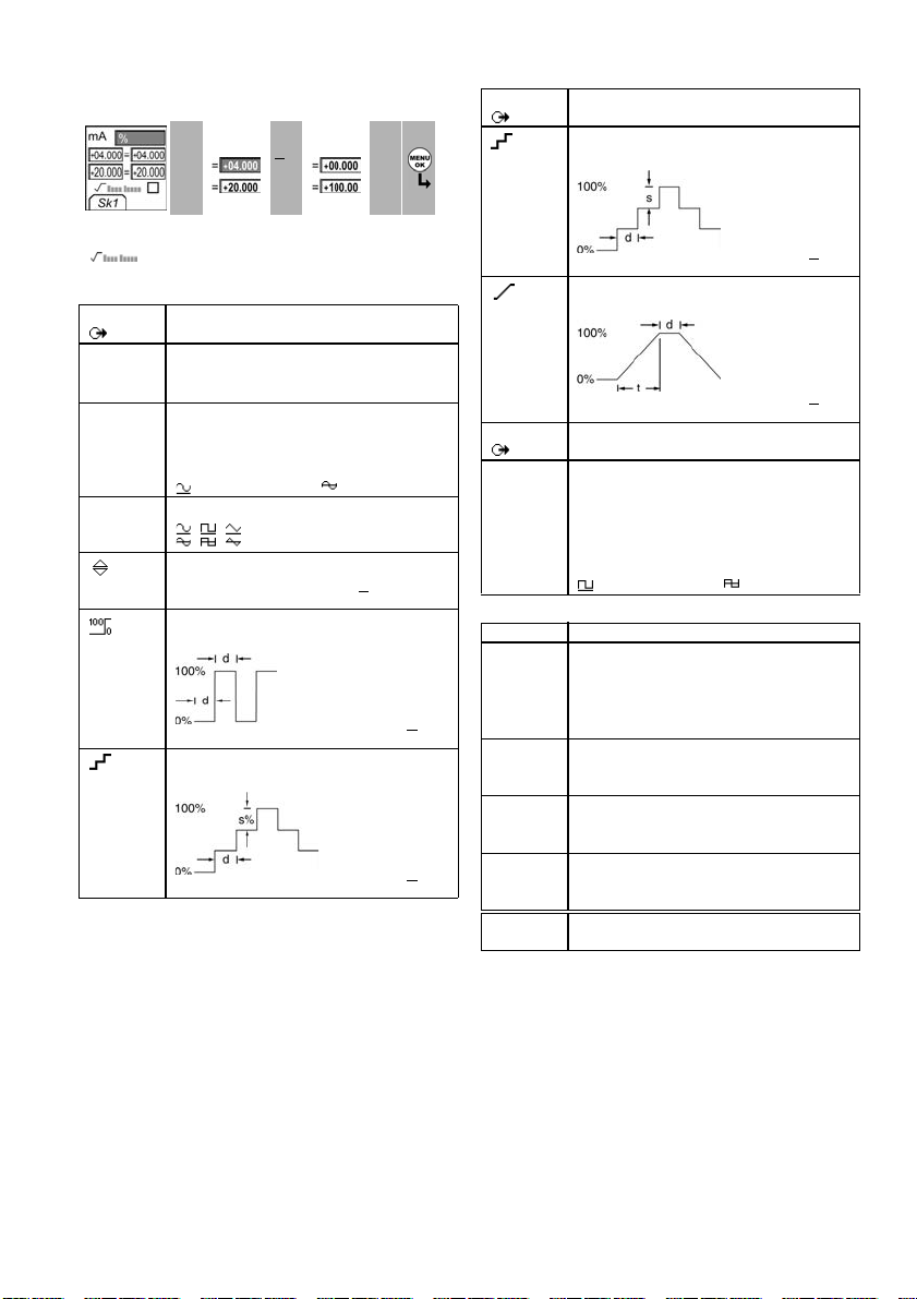
Set up the settings ......................................................................... 4
Edit functions .................................................................................... 4
Operation .............................................................................. 6
Frequency connections ............................................................... 6
Communications port connections ........................................ 6
Measure Hz or count pulses ...................................................... 6
Change the output values .......................................................... 6
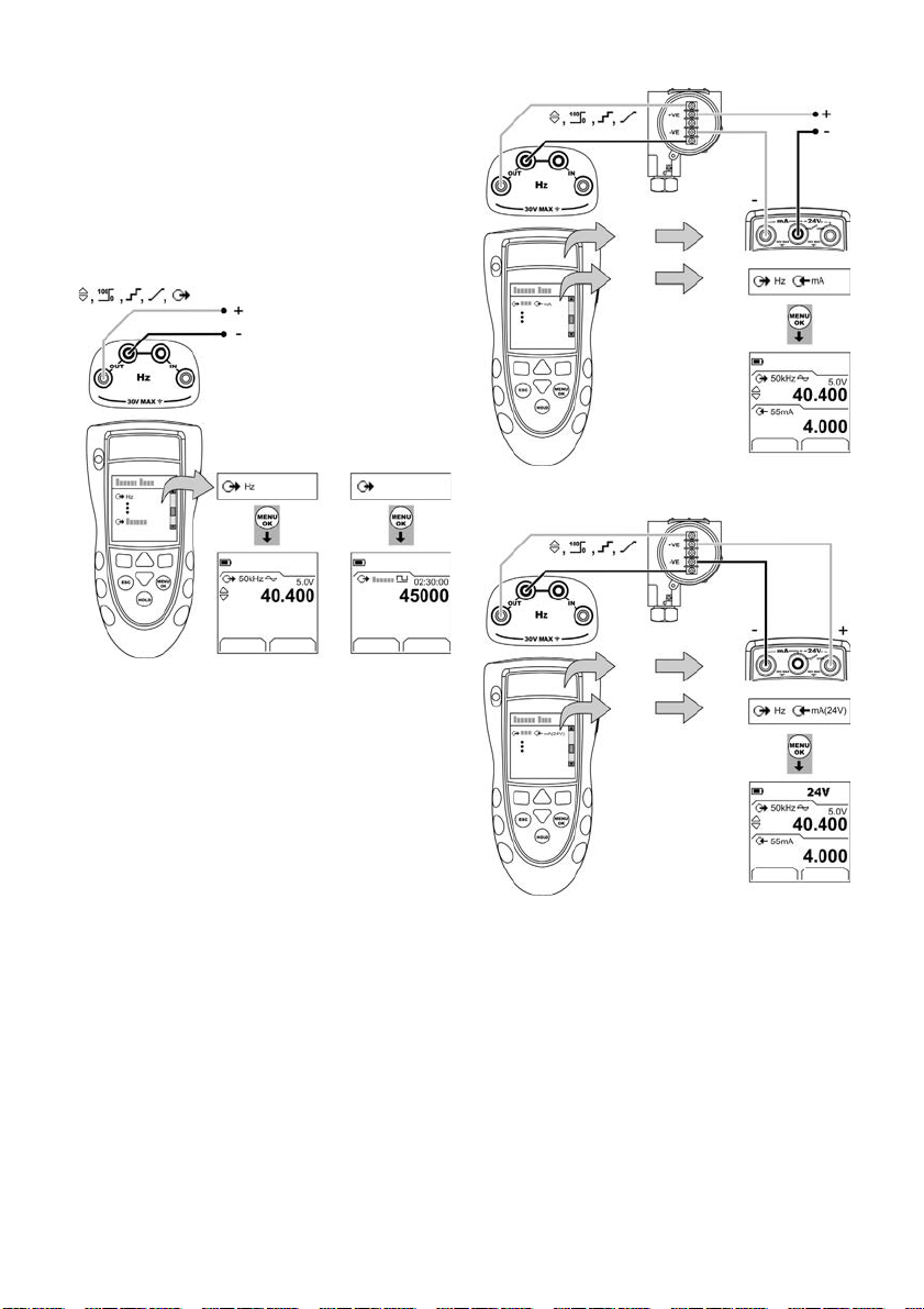
Supply Hz or pulses ........................................................................ 7
Transmitter calibration ................................................................ 7
mA measurements ........................................................................ 8
Switch test .......................................................................................... 8
UPM Pressure measurements .................................................. 9
Error indications .............................................................................. 9
Maintenance ..................................................................... 10
Clean the unit ................................................................................ 10
Replace the batteries ................................................................. 10
Calibration ......................................................................... 10
Before you start ............................................................................ 10
Procedures (Hz - input/output) .............................................. 10
Procedures (mA input) ............................................................... 11
Procedures (Amplitude output) ............................................. 11
Procedures (IDOS UMM) ............................................................ 12
Specification data ............................................................ 12
General ............................................................................................. 12
Frequency ....................................................................................... 12
Electrical connectors (A2) ......................................................... 12
Customer service ............................................... Back cover
© 2007 General Electric Company. All rights reserved.
Trademarks
All product names are trademarks of their respective companies.
Introduction
The DPI 841 Frequency Calibrator and DPI 842 Frequency
Loop Calibrator are part of the Druck DPI 800 series of
hand held instruments.
The DPI 800 series uses Intelligent Digital Output Sensor
(IDOS) technology to give instant plug and play
functionality with a range of Universal Measurement
Modules (UMM). Example: the Universal Pressure Module
(UPM).
The DPI 841/842 include these functions:
Safety
Before you use the instrument, make sure that you read
and understand all the related data. This includes: all local
safety procedures, the instructions for the UMM (if
applicable), and this publication.
WARNING
• It is dangerous to ignore the specified limits for the
instrument or to use the instrument when it is not in
its normal condition. Use the applicable protection
and obey all safety precautions.
• Do not use the instrument in locations with explosive
gas, vapor or dust. There is a risk of an explosion.
Continued
Function DPI 841 DPI 842
Measure/supply a frequency
or a pulse count.
* Yes
* Refer to “Specification data”.
** Optional item
Step/Ramp functions Automatic/Manual
Communications port IDOS or RS232
Language selection Yes
Measure pressure/Leak test ** External IDOS UPM
** Snapshot Up to 1000 displays with a date/time
stamp
Measure mA No 0 - 55 mA
HART®resistor No Yes
V dc output No 24 V
Switch test No Yes
Other functions Hold, Maximum/Minimum/Average,
Filter, Tare, Scaled values, Backlight,
Alarm

2- [EN] English K395 Issue 3
Safety (Continued)
• To prevent electrical shocks or damage to the
instrument, do not connect more than 30V between
the terminals, or between the terminals and the
ground (earth).
• UPM only. To prevent a dangerous release of
pressure, isolate and bleed the system before you
disconnect a pressure connection.
Before you start an operation or procedure in this
publication, make sure that you have the necessary skills
(if necessary, with qualifications from an approved training
establishment). Follow good engineering practice at all
times.
Safety - Marks and symbols on the instrument
To start
To start - Location of items …
To start - Items on the display
To start - Prepare the instrument
Before you use the instrument for the first time:
• Make sure that there is no damage to the instrument,
and that there are no missing items.
• Remove the plastic film that protects the display. Use
the tag (◗) in the top right-hand corner.
• Install the batteries (refer to B1). Then re-attach the
cover.
Complies with European
Union directives
Warning - refer to the
manual
Read the manual Battery
Ground (Earth) ON/OFF
Do not dispose of this product as household waste. Refer to
“Maintenance”.
Item Description
1. ❍On or off button.
2. ■■Left-hand soft-key. Selects the function above it on
the display (Item 25). Example: Edit
3.
ESC
Moves back one menu level.
Leaves a menu option.
Cancels the changes to a value.
4. ▲
▼
Increases or decreases a value.
Highlights a different item.
5. HOLD Holds the data on the display. To continue, press the
HOLD button again.
6. MENU
OK
Shows the Select Task menu.
Selects or accepts an item or value.
Selects [✓] or cancels [ ] a selection.
7. ■■Right-hand soft-key. Selects the function above it on
the display (Item 25). Example: Settings
8. Display. Refer to A3
9. SENSOR
/ PC
Communications port. Use to connect a Universal
Measurement Module (UMM) or a RS232 cable.
10. IN
OUT
Terminals to measure (IN) or supply (OUT) a frequency
or a pulse rate. Refer to “Operation”.
11. Connection point for some of the optional
accessories. Refer to the datasheet.
12. Battery compartment. Refer to B1.
13., 14., 15. DPI 842 only. Terminals to measure current, to supply
24V source, and to do switch tests.
A1 A2
Item Description
16. DPI 842 only. Task indication for the switch test.
= switch closed = switch open
UPM only. Task indication for the leak test.
Refer to: Select Task (Table 2/3)
17. DPI 842 only. The loop power supply is on.
Refer to: Select Task (Table 2/3)
18. The measured value satisfies one of the alarm
conditions. Refer to: Settings (Table 4)
19. The data on the display is on hold. To continue, press
the HOLD button again.
20. Shows the battery level: 0 ... 100%.
21. Identifies the type of data and the measurement
range.
= Input = Output
= IDOS input
Refer to: Select Task (Table 2/3)
22. ... 24. The settings applied to the input or output.
22. kHz The units or a specified scale (x:y) - (Table 4/5)
, , =
Output waveform (Table 5)
5.0V ...V The input trigger level (Table 4) or the output
amplitude (Table 5).
23. , ... , = Output operation (Table 5)
24. = Filter
= Tare
= Maximum
= Average
= Minimum
(Table 4)
25. A soft-key function. To select an available function,
press the soft-key below it. Example:
= Move left = Move right
26. The measured value or values applicable to the task
selection.
27. The Edit display to set up text labels ( ≤6 characters):
x:y Scaling (Table 4).
OK = Accept the new text label
Shift = Change the keys: 123ABC or -_+abc
= Add a space
BS = Back space (Delete character)
A3

[EN] English - 3
K395 Issue 3
To start - Power on or off
To turn the instrument on or off, press ❍(A1 - item [1]). The
instrument does a self test and then shows the applicable
data.
When the power is off, the last set of configuration options
stays in memory. Refer to “Maintenance”.
To start - Set up the basic operation
Use the Set Up menu to set up the basic operation of the
instrument.
If there is additional data for a menu option, select
Settings (■■) to see the values that are set up. If
necessary, adjust the values.
Table 1: Menu options - Set Up
To start - Select a task (Measure and/or supply)
When the instrument is set up (Table 1), use the Select Task
menu to select the applicable task.
In Table 2/3, IDOS is a Universal Measurement Module
(UMM). If you attach a UMM to the communications port
(A1 - item [9]), the Select Task menu shows the applicable
IDOS options.
Table 2: Menu options - Select Task
Table 3 shows all the one and two function operations that
are available. If you attach a UMM, you can only use the
options that include IDOS.
Table 3: Permitted 1 and 2 function operations
1Menu:
Select Task 23 Menu:
Set Up 45
▲
▼
▲
▼
(Table 2) (Table 1) [✓]/[ ]
Options
(If applicable)
Description
DPI 842 only. To add a series resistor into the mA
circuit. You can then use this instrument together
with a HART®communicator to set up and
calibrate HART®devices.
To select and set up the backlight facility + timer.
Additional data: Select Settings (■■)
To select and set up the power off facility + timer.
Additional data: Select Settings (■■)
To show the battery level (%).
To set the display contrast (%).
▲ Increases %, ▼ decreases %
To set the time + date. The calibration facility uses
the date to give service and calibration messages.
To set the language option.
To calibrate the instrument.
Additional data: Refer to “Calibration”.
To select and show the applicable status data.
(Software Build, Calibration Due date, Serial
Number, IDOS Information).
1Menu:
Select Task 23 Display:
Hz output
▲
▼
(Table 2/3) Sk1 = Edit
Sk2 = Settings
Options
(If applicable)
Description
Hz or
Pulses
An input measurement task:
Hz - Measure the frequency
Pulses - Count the number of pulses
Hz or
Pulses
An output task:
Hz - Supply an output frequency
Pulses - Generate a specified number of pulses
mA DPI 842 only. A mA measurement task.
mA(24V) DPI 842 only. A mA measurement task + the loop
power supply is on.
DPI 842 only. A switch test.
IDOS UMM only. An IDOS measurement task.
UPM only. A leak test.
To set up the way the instrument works.
Additional data: Refer to: Set Up (Table 1).
Function
Hz Hz Pulses Pulses
IDOS
(1) (1) (1) (1) (1)
mA (1) x(2) x x (2)
mA(24V) (1) x(2) x x (2)
x x (2) x x (2)
xxxxx(2)
IDOS (1) (2) (2) (2) x x
= DPI 842 only

4- [EN] English K395 Issue 3
To start - Set up the settings
When the task is set up (Table 2/3), use the Settings menu
to adjust the input and/or output operation.
If there is additional data for a menu option, select
Settings (■■) to see the values that are set up. If
necessary, adjust the values. Refer to “Edit functions”.
Table 4: (Part of table) Menu options - Settings (Input)
To start - Edit functions
Example 1) Set up a label for x:y Scaling = %.
Display: Task
Hz + mA 1Settings selection
(If applicable) 23
■■▲
▼
Sk1 = Start/Stop
Sk2 = Settings
Menu:
Settings 4A 5A 6A Settings
x:y
▲
▼■■
(Table 4) [✓]/[ ] Sk1 = Edit
Menu:
Settings 4B 5B
▲
▼
(Table 5) [●]/[ ]
Options
(If applicable)
Description
... Units Frequency Units (Hz input only). To select one of
these units:
Hz: Range <1000Hz kHz: Range 1 ... 50kHz
Pulses/minute (cpm) Pulses/hour (cph)
... Units UPM only = “Pressure Units” if you select an IDOS
task (Table 2/3). Select one of the fixed units of
measurement (psi, mbar ... ).
Trigger level To set the amplitude at which the instrument
senses a frequency signal. Default = 5V.
Auto Detect [✓]/[ ]: Set this option to make the
instrument calculate the value from the available
signal.
To include maximum, minimum and average
values for the measurement task.
Options
(If applicable)
Description
To select and set up a tare value for the
measurement task (a specified value or the reading
on the display).
The instrument subtracts a positive tare value, and
adds a negative tare value.
Additional data: Select Settings (■■)
To select and set up a scale of values: One local
scale for each measurement task (Maximum: 5).
Additional data (Example 1/2): Select Settings (■■)
To select and set up the filter values to give a
smoother output for the measurement task:
Band as a % of full scale (FS). The filter
compares each new value with the previous
value. If the new value is outside the band, it is not
filtered.
Low pass filter time constant in seconds.
Increase the value to increase damping
factor.
Additional data: Select Settings (■■)
To select and set up the alarm values for the
measurement task (maximum and minimum).
Additional data: Select Settings (■■)
UPM only. Gage sensors or sensors with differential
operation. A zero correction that makes the
instrument read zero at local pressure.
Leak Test only. To set an applicable period for the
leak test (Hours:Minutes:Seconds).
Settings
x:y 1Edit 2Edit 3
■■
▲
▼
■■
Sk1 = Edit A3 - item [27]
Edit ... Edit 45
%_
▲
▼
■■
A3 - item [27]
Shift
OK

[EN] English - 5
K395 Issue 3
Example 2) Set up values for x:y Scaling = 0 to 100%.
Table 5: (Part of table) Menu options - Settings (Output)
Table 6: Additional data for Settings (Output):
Settings
x:y 1Settings
x:y 2Edit 34
▲
▼
■■
▲
▼
■■
Sk1 = Edit
= Flow scaling (mA, pressure only)
Options
Hz
Description
... Units Frequency Units. To select one of these units:
Hz: Range <1000Hz kHz: Range 1 ... 50kHz
Pulses/minute (cpm) Pulses/hour (cph)
Amplitude To set the amplitude and the mode of the output
signal. Amplitude = 5V (Default).
Bipolar mode [✓]/[ ]: Set this option to make the
signal pass thru zero.
= Unipolar = Bipolar
Waveform To set the waveform for the output signal:
,, = Sine, square, or triangle
To select and set up a value for the “Nudge” output.
Example: 0.010 kHz increments.
Additional data: Select Settings (■■)
To select and set up values for the “Span Check”
output. Example output cycle:
This cycle repeats
automatically.
Additional data (Table 6): Select Settings (■■)
% Step To select and set up values for the “% Step” output.
Example output cycle:
Auto Repeat - Optional
Additional data (Table 6): Select Settings (■■)
Options
Hz
Description
... Step To select and set up values for the “Defined Step”
output. Example output cycle:
Auto Repeat - Optional
Additional data (Table 6): Select Settings (■■)
To select and set up values for the “Ramp” output.
Example output cycle:
Auto Repeat - Optional
Additional data (Table 6): Select Settings (■■)
Options
Pulses
Description
Counts: To set the total number of output pulses.
Rate: To set the frequency of the output.
Amplitude: To set the amplitude of the output
signal. Amplitude = 5V (Default).
Bipolar mode [✓]/[ ]: Set this option to make the
signal pass thru zero.
= Unipolar = Bipolar
Item Value
Span Check
Low (0%) Set the 0% value.
High (100%) Set the 100% value.
Dwell (d) Set the period (Hours:Minutes:Seconds) between
each change in value.
% Step Low (0%), High (100%), Dwell (d): As above.
Step Size (s) ...
%
Set the change in value for each step as a
percentage of the full-scale range (High - Low).
Defined Step Low (0%), High (100%), Dwell (d): As above.
Step Size (s) Set the change in value for each step as a
frequency value.
Ramp Low (0%), High (100%), Dwell (d): As above.
Travel (t) Set the period (Hours:Minutes:Seconds) to go from
the Low (0%) value to the High (100%) value.
Auto Repeat If applicable, select this item to repeat a cycle
continuously.

6- [EN] English K395 Issue 3
Operation
This section gives examples of how to connect and use the
instrument. Before you start:
• Read and understand the “Safety” section.
• Do not use a damaged instrument.
Operation - Frequency connections
To prevent instrument errors, make sure that the
frequency connections (A1-item [10]) are correct.
Operation - Communications port connections
Use the communications port (A1 - item [9]) to attach an
IDOS Universal Measurement Module (UMM).
When you attach the cable from a UMM (Figure 7/8), the
instrument automatically changes the menus to give you
all the applicable options (Table 2/3).
Operation - Measure Hz or count pulses
To measure Hz or count pulses:
1. Connect the instrument (Figure 1) and, if necessary,
adjust the Set Up (Table 1).
2. Select a Hz or Pulses input task from Select Task
(Table 2/3) and, if necessary, adjust the Settings
(Table 4).
3. For Pulses, use Start/Stop (■■) to start and stop the
count. The display shows the time (hh:mm:ss) since you
started the count.
Figure 1: Example configuration - To measure Hz
or count Pulses
Operation - Change the output values
When the output operation is set up (Table 5), use one of
these procedures to change the output values:
Table 7: Procedures to change the output
Example procedure (“Nudge” output):
SettingsStartSettings
Pulses
a) Hz b) Pulses
Output Procedure
Select Edit (■■) and/or use the ▲▼buttons.
See the example below.
, Select Start/Stop (■■) or use the ▲▼buttons
to make the step changes manually.
,
Pulses
Select Start/Stop (■■).
Display:
Hz output 1Edit 23Edit 4
■■ ■ ■▲
▼+01.000
Sk1 = Edit
Sk2 = Settings
Display:
Hz output 56
▲
▼1.010 ▲
▼1.020
Increment = 0.010
(Table 5)

[EN] English - 7
K395 Issue 3
Operation - Supply Hz or pulses
To supply Hz or pulses:
1. Connect the instrument (Figure 2) and, if necessary,
adjust the Set Up (Table 1).
2. Select a Hz or Pulses output task from Select Task
(Table 2/3) and, if necessary, adjust the Settings
(Table 5).
For Pulses, the display shows the time (hh:mm:ss) to
complete the count at the specified rate.
3. Supply the output values to the system (Table 7).
Figure 2: Example configuration - To supply Hz or Pulses
Operation - Transmitter calibration
DPI 842 only. To calibrate a transmitter:
1. Connect the instrument (Figure 3/4) and, if necessary,
adjust the Set Up (Table 1).
2. Select the applicable calibration task from Select Task
(Table 2/3) and, if necessary, adjust the Settings
(Table 4/5).
3. Supply the output values to the system (Table 7).
Figure 3: Example configuration - Transmitter calibration
with external loop power
Figure 4: Example configuration - Transmitter calibration
with internal loop power
Edit Settings Start Settings
a) Hz b) Pulses
Pulses
Pulses
Edit Settings
Maximum: 30V
Edit Settings

8- [EN] English K395 Issue 3
Operation - mA measurements
DPI 842 only. To measure a current:
1. Connect the instrument (Figure 5) and, if necessary,
adjust the Set Up (Table 1).
2. Select the applicable mA input task from Select Task
(Table 2/3) and, if necessary, adjust the Settings
(Table 4).
Figure 5: Example configuration - mA measurement
Operation - Switch test
DPI 842 only. To do tests on a frequency operated switch:
1. Connect the instrument (Figure 6) and, if necessary,
adjust the Set Up (Table 1).
2. Select the applicable switch test from Select Task
(Table 2/3) and, if necessary, adjust the Settings
(Table 5). The display shows the switch condition (open
or closed) in the top right-hand corner.
3. Supply the output values to the system (Table 7).
• Example - “Nudge” output.
a. Use Edit (■■) to set a value less than the switch
value.
b. Use the ▲▼buttons to change the value in small
increments.
• Example - “Ramp” output.
a. Set “High” and “Low” values that are applicable to
the switch value (Table 6). Then, to get an accurate
switch value, set a long “Travel” period.
b. Use Start/Stop (■■) to start and stop the “Ramp”
cycle.
4. If necessary, supply the output values in the opposite
direction until the switch changes condition again.
The display shows the applicable values to open and
close the switch.
5. To do the test again, press ESC to reset the values.
Figure 6: Example configuration - Switch test
Settings Settings
a) with external loop
power
b) with internal loop
power
Maximum: 30V
Edit Settings

[EN] English - 9
K395 Issue 3
Operation - UPM Pressure measurements
Read all the instructions supplied with the UPM and then
use the specified procedures to connect it (Figure 7/8).
Figure 7: Example configuration - Pressure measurement
with a UPM
When the connections are complete, make the necessary
IDOS selections (Table 2/3).
If you re-attach a UPM, the instrument uses the same
measurement units that you used before. The instrument
keeps a record for the last 10 modules.
UPM - Measure the pressure
To measure the pressure (Figure 7):
1. Select the applicable pressure task from Select Task
(Table 2/3) and, if necessary, adjust the Set Up (Table 1),
and the Settings (Table 4/5).
2. If necessary, do a zero correction (Table 4).
To measure pressure with another operation (Figure 8), use
the same procedure.
Figure 8: Example configuration - To measure pressure
and frequency
UPM - Leak test
To do a leak test on a pressure system (Figure 7):
1. Select an applicable leak test from Select Task
(Table 2/3) and, if necessary, adjust the Set Up (Table 1),
and the Settings (Table 4).
2. Set the period for the leak test (Table 4).
3. If necessary, do a zero correction (Table 4).
4. To start the leak test, select Start (■■). When the test is
finished, the instrument calculates the leak rate in the
applicable units/minute.
Operation - Error indications
If the display shows <<<< or >>>> :
• Make sure that the range is correct.
• Make sure that all the related equipment and
connections are serviceable.
Settings
a) Pressure b) Leak test
Start Settings
Settings

10 - [EN] English K395 Issue 3
Maintenance
This section gives procedures to maintain the unit in a
good condition. Return the instrument to the
manufacturer or an approved service agent for all repairs.
Do not dispose of this product as household waste. Use an
approved organisation that collects and/or recycles waste
electrical and electronic equipment.
Maintenance - Clean the unit
Clean the case with a moist, lint-free cloth and a weak
detergent. Do not use solvents or abrasive materials.
Maintenance - Replace the batteries
To replace the batteries, refer to B1. Then re-attach the
cover.
Make sure that the time and date are correct. The
calibration facility uses the date to give service and
calibration messages.
All the other configuration options stay in memory.
Calibration
Note: GE can provide a calibration service that is traceable
to international standards.
We recommend that you return the instrument to the
manufacturer or an approved service agent for
calibration.
If you use an alternative calibration facility, make sure that
it uses these standards.
Calibration - Before you start
To do an accurate calibration, you must have:
• the calibration equipment specified in Table 8.
• a stable temperature environment: 70 ± 2°F (21 ± 1°C)
Table 8: Calibration equipment
Before you start the calibration, make sure that the time
and date on the instrument are correct (Table 1).
Selection sequence:
➤
Select Task (Table 2)
➤
Set Up (Table 1)
➤
Calibration
➤
.
Table 9: Calibration options
When you select a channel, the display shows the
applicable instructions to complete the calibration.
When the calibration is complete, select Calibration Due
and set the new calibration date for the instrument.
Calibration - Procedures (Hz - input/output)
1. Connect the instrument to the calibration equipment
(Figure 1).
2. Let the equipment get to a stable temperature
(minimum: 5 minutes since the last power on).
3. Set up the equipment with these conditions:
4. Use the calibration menu (Table 9) to do the calibration.
The display shows the applicable instructions to
complete the calibration.
Function Calibration equipment
(ppm = parts per million)
Hz 1) Frequency meter
Total error: 7 ppm or better
Resolution: 8 digits (minimum)
2) Signal generator
Pressure UPM only. Refer to the user manual for the IDOS
UPM.
mA mA calibrator.
Accuracy: Refer to Table 12.
Amplitude (V) 1) Frequency meter
Total error: 7 ppm or better
Resolution: 8 digits (minimum)
2) Digital volt meter (DVM)
B1
1Display: Enter
Calibration PIN 23 Menu:
Select Channel 45
▲
▼
+
■■
▲
▼
Factory PIN = 4321 (Table 9)
Options Description
Hz To calibrate the input or output frequency.
... Amplitude. To select and calibrate the output
amplitude for the Square Wave and then the
Sine/Triangular Wave.
IDOS ... UMM only. To calibrate the specified IDOS UMM.
Refer to the user manual for the IDOS UMM.
mA DPI 842 only. To calibrate the mA input.
Calibration Due: To set the date of the next
calibration for the instrument.
After the specified calibration date, there is a
warning message. There is a selection box to stop
the warning.
To change the calibration PIN (Personal
Identification Number).
Frequency meter: Gate time = one second
Signal generator: Output = 10V, unipolar,
square wave
Frequency = 990 Hz
DPI 841/842: Input units = Hz (Table 4)
Input trigger level = 5V (Table 4)

[EN] English - 11
K395 Issue 3
5. To make sure that the calibration is correct, set up the
equipment to do one of these calibration checks:
• Hz input calibration check (Figure 1):
• Hz output calibration check (Figure 2):
6. Measure or supply the specified values (Table 10/11):
Hz then kHz. Make sure that the error is in the specified
limits.
Table 10: Hz error limits (Measure/Supply)
Table 11: kHz error limits (Measure/Supply)
Calibration - Procedures (mA input)
1. DPI 842 only. Connect the instrument to the calibration
equipment (Figure 5).
2. Let the equipment get to a stable temperature
(minimum: 5 minutes since the last power on).
3. Use the calibration menu (Table 9) to do a three-point
calibration (-FS, Zero and +FS). The display shows the
applicable instructions to complete the calibration.
4. To make sure that the calibration is correct, select the
applicable mA input task (Table 2) and apply these
values:
• mA: -55, -40, -24, -18, -12, -6, 0 (open circuit)
Then mA: 0, 6, 12, 18, 24, 40, 55.
5. Make sure that the error is in the specified limits
(Table 12).
Table 12: mA input error limits
Calibration - Procedures (Amplitude output)
1. Connect the instrument to the calibration equipment
(Figure 2).
2. Let the equipment get to a stable temperature
(minimum: 5 minutes since the last power on).
3. Set up the DPI 841/842 with these conditions:
4. Use the calibration menu (Table 9) to do the Square
Wave calibration. The display shows the applicable
instructions to complete the calibration.
5. Change the output waveform to Sine Wave (Table 5).
6. Use the calibration menu (Table 9) to do the
Sine/Triangular Wave calibration. The display shows
the applicable instructions to complete the calibration.
Frequency meter: Gate time = one second
Signal generator: Output = 10V, unipolar,
square wave
DPI 841/842: Input trigger level = 5V (Table 4)
Units (Table 4): Hz or kHz as
specified in Table 10/11.
Frequency meter: Gate time = one second
DPI 841/842: Units (Table 5): Hz or kHz as
specified in Table 10/11.
Measure/
Supply
Calibrator
error (Hz)
Permitted
DPI 841/842 error (Hz)
Hz
25 0.000175 0.002 0.0014
100 0.0007 0.002 0.0021
250 0.00175 0.004 0.0035
500 0.0035 0.006 0.0058
990 0.00693 0.011 0.0104
Measure/
Supply
Calibrator
error (kHz)
Permitted
DPI 841/842 error (kHz)
kHz
2.5000 0.0175 0.0002 0.000042
10.0000 0.07 0.0002 0.000112
20.0000 0.14 0.0003 0.000205
30.0000 0.21 0.0004 0.000298
50.0000 0.35 0.0006 0.000483
Applied
mA
Calibrator
error
(mA)
Permitted
DPI 841/842 error
(mA)
±55 0.0022 0.005
±40 0.0018 0.004
±24 0.0014 0.003
±18 0.0004 0.003
±12 0.0003 0.002
±6 0.0002 0.002
0 (open circuit) - 0.001
Output Hz = 0 (For direct current output)
Output amplitude: Set to Unipolar (Table 5)
Output waveform = Square Wave (Table 5)
Calibration values: Low = 0.1V, High = 20V

12 - [EN] English K395 Issue 3
7. To make sure that the calibration is correct, set up the
DPI 841/842 with these conditions:
8. Supply the specified values (Table 13): Square Wave
then Sine Wave. Make sure that the error is in the
specified limits.
Table 13: Amplitude output error limits
Calibration - Procedures (IDOS UMM)
Refer to the user manual for the IDOS UMM.
When the calibration is complete, the instrument
automatically sets a new calibration date in the UMM.
Specification data
All accuracy statements are for one year.
Specification - General
Specification - Frequency
cpm = Pulses/minute, cph = Pulses/hour
Specification - Electrical connectors (A2)
Output Hz = 0 (For direct current output)
Output amplitude: Set to Unipolar (Table 5)
Amplitude
Volts (V)
Permitted
DPI 841/842 error
(V)
0.1 0.05
1.0 0.10
10.0 0.10
15.0 0.15
24.0 0.24
Languages English [Default]
Operating
temperature
14 … 122°F (-10 … 50°C)
Storage
temperature
-4 … 158°F (-20 … 70°C)
Humidity 0 to 90% without condensation
(Def Stan 66-31, 8.6 cat III)
Shock/Vibration BS EN 61010:2001; Def Stan 66-31, 8.4 cat III
EMC BS EN 61326-1:1998 + A2:2001
Safety Electrical - BS EN 61010:2001; CE Marked
Size (L: W: H) 7.1 x 3.3 x 2.0 in
(180 x 85 x 50 mm)
Weight 14 oz (400 g)
Power supply 3 x AA alkaline batteries
Duration
(Measure)
Hz, pulses: ≈ 60 hours
mA: ≈ 35 hours
mA: ≈ 10 hours (24 V Source at 12 mA)
Duration
(Supply)
Hz, pulses: ≈ 20 hours
Range (Measure): Accuracy:
0 ... 999.999 Hz
1 ... 50.0000 kHz
cpm: 0 ... 99999
cph: 0 ... 99999
For all the ranges:
0.003% of reading + 2 counts
Range (Supply): Accuracy:
0 ... 999.99 Hz
1 ... 50.000 kHz
cpm: 0 ... 99999
cph: 0 ... 99999
0.003% of reading + 0.0023 Hz
0.003% of reading + 0.0336 Hz
0.003% of reading + 0.138 cpm
0.003% of reading + 0.5 cph
Temperature coefficient
14 … 50°F, 86 … 122°F
(-10 … 10°C, 30 … 50°C)
0.0011% FS / °F
(0.002% FS / °C)
Waveform
(Sine, square, triangle)
Unipolar
Bipolar
Voltage input 0 ... 30 V
Trigger level 0 ... 24 V, Resolution: 0.1 V
Output amplitude 0 ... 24 V dc ± 1%
0 ... 24 V ac ± 5% (Current ≤20 mA)
Connectors (A1 - Item 10) Four 0.16 in (4 mm) sockets
Range (Measure) 0 to ±55 mA
Accuracy 0.02% of reading + 3 counts
Temperature coefficient
14 … 50°F, 86 … 122°F
(-10 … 10°C, 30 … 50°C)
0.0011% FS / °F
(0.002% FS / °C)
Switch detection Open and closed. 2 mA current.
Loop power output 24 V ± 10%
HART®resistor 250 Ω (menu selection)
Connectors (A2) Three 0.16 in (4 mm) sockets
Test Equipment Depot - 800.517.8431
99 Washington Street, Melrose, MA 02176
TestEquipmentDepot.com
This manual suits for next models
1
Table of contents
Other Druck Test Equipment manuals

Druck
Druck DPI 610 IS User manual

Druck
Druck PV 62XG User manual

Druck
Druck UPS-III-IS User manual

Druck
Druck DPI620 Genii User manual

Druck
Druck PTC200 User manual

Druck
Druck TRX User manual

Druck
Druck DPI 610E User manual

Druck
Druck ADTS 403R Use and care manual

Druck
Druck DPI 620 Genii Instruction Manual

Druck
Druck InstruMetrics ADTS542F Setup guide