SCHUNK GFT-X 270 User manual

Operating Manual
Hardware/Software Version 1.8/1.5
Date: December 2012
H.-D. SCHUNK GMBH & CO. SPANNTECHNIK KG
Lothringer Straße 23, D-88512 Mengen
Tel. +49-(0)-7572-7614-0, Fax +49-(0)-7572-7614-99
Manufactured exclusively by
MESA Systemtechnik GmbH D-78467 Konstanz

Gripping Force Tester GFT®-X 270 Rev. 1.8/1.5 12/2012 page 2
H.-D. SCHUNK GMBH & CO. SPANNTECHNIK KG Lothringer Straße 23 D-88512 Mengen
Tel. +49-(0)-7572-7614-0 Fax +49-(0)-7572-7614-99 www.schunk.de
Congratulations on your new Gripping Force Tester GFT®-X 270! You have made an excellent
choice in buying this innovative technology which offers a variety of advantages in its use. In
order to avoid handling errors you should take a few minutes and read these operating manual
carefully.
When you have read these manual you should keep them safely at a place where they can be
easily accessed so you can refer to them again at any time. Keep your Gripping Force Tester
GFT®-X 270 in the transport case where it has optimum protection. When the device is
dispatched for maintenance or repair, it must also be sent in the transport case so that the
sensitive parts are protected in an optimum way during transportation.
The information and data contained in these operating manual may be modified without prior
notice. No part of this documentation may be reproduced or transmitted for any purpose
whatsoever, regardless of the mode or the means, electronically or mechanically, without the
prior permission in writing of MESA Systemtechnik GmbH.
In order to protect the unit against fire, electric shock or potential destruction of the electronic
components, it must never be exposed to rain or extreme humidity. Direct sun or heat are to be
avoided as well.
Please do not try to open the hand-held unit or the measuring device. There are no parts inside
which you could maintain.
All data in this publication have been compiled and checked with utmost diligence, nevertheless
errors and mistakes cannot be totally excluded.
All modifications, in particular those relating to technological improvements, are reserved.
©2012 MESA Systemtechnik GmbH Konstanz All rights reserved.

Gripping Force Tester GFT®-X 270 Rev. 1.8/1.5 12/2012 page 3
H.-D. SCHUNK GMBH & CO. SPANNTECHNIK KG Lothringer Straße 23 D-88512 Mengen
Tel. +49-(0)-7572-7614-0 Fax +49-(0)-7572-7614-99 www.schunk.de
Table of Contents
1Introduction 5
2Safety information 5
2.1 Introduction 5
2.2 Safety information pictograms 5
3System requirements 5
4Introduction 6
4.1 Packing list 6
5Overview 7
6Technical Data 8
6.1 GFT®-X Handheld Unit 8
6.2 Measuring Heads for collets 8
6.3 Measuring Heads for jaw chucks 9
6.4 Mains / Battery operation 9
7Handheld GFT®-X 10
7.1 Overview 10
7.2 Keyboard GFT®-X Handheld Unit 10
7.3 Status Line 11
7.4 LED indicator 12
7.5 Speed Buttons 12
7.6 Menu GFT®-X Hand Held - outline 13
7.6.1 Menu-Overview 14
7.6.2 Measuring 15
7.6.2.1 Measuring Head Recalibration 15
7.6.2.2 Recharge Measuring Head 16
7.6.3 Define new data collection 16
7.6.4 Settings 17
7.6.5 Menu Measuring Head 18
7.6.6 Menu collet chuck 19
7.6.7 Select Language 19
8Measuring Head 20
8.1 Measuring Head M1 and M2 for collets 20
8.2 Measuring Head M3 and M4 for jaw chuck 21
8.2.1 Measuring Head Extension Cylinder for M3 und M4 23
8.2.2 Mounting M3 und M4 Measuring Head 23
8.3 Measuring procedere 24
8.3.1 Static Measuring 24
8.3.2 Dynamic Measuring 24

Gripping Force Tester GFT®-X 270 Rev. 1.8/1.5 12/2012 page 4
H.-D. SCHUNK GMBH & CO. SPANNTECHNIK KG Lothringer Straße 23 D-88512 Mengen
Tel. +49-(0)-7572-7614-0 Fax +49-(0)-7572-7614-99 www.schunk.de
9Calibration, Recalibration 25
10 Maintenance, Service 25
11 Measured data display / storage on PC 26
11.1 Installing ChuckExplorer 26
11.2 Using the software 28
11.2.1 Measurement 30
11.2.2 Measurement preparations 30
11.2.3 Manual measuring 31
11.2.4 Automatic measuring 31
11.3 Download data from GFT®-X Handheld Unit 32
11.4 Loading and saving files 32
12 Software update 33
12.1 Problems with the Update of the GFT-X Handheld Unit cause / corrective 35
13 Trouble shooting / FAQ´s 36
13.1 Problems at GFT®-X Handheld Unit cause / corrective 36
13.2 Problems with Chuck Explorer – cause / corrective 36
14 How to change the power plug at mains adapter 38
15 Changing the battery of the Handheld Unit 39
16 Accessories / spare parts list 40

Gripping Force Tester GFT®-X 270 Rev. 1.8/1.5 12/2012 page 5
H.-D. SCHUNK GMBH & CO. SPANNTECHNIK KG Lothringer Straße 23 D-88512 Mengen
Tel. +49-(0)-7572-7614-0 Fax +49-(0)-7572-7614-99 www.schunk.de
1 Introduction
This manual contains important information about connection and safety operation of the
Gripping Force Testers GFT®-X270. Please read the safety instruction carefully.
2 Safety information
2.1 Introduction
The Gripping Force Tester GFT®-X 270 is constructed according to DIN EN 61010-1; VDE
0411-1:2009-06. At the upper front face the Handheld Unit contains an USB slave connector for
data communication with a Windows®based computer and for power supply / recharging. The
Power Supply Plug operates in the range of 100V~-240V~ alternating current and complies with
EN60950-1 and UL60950-1.
2.2 Safety information pictograms
Helpfull Information / Hints
Pictogram advices helpfull informations and hints.
Danger!
Please read observantly, non-compliance may result in risk of severe damage to
your health.
Warning!
Non-compliance may result in risk of damage at the GFT-X.
3 System requirements
Operating Systems
•Windows 2000
•Windows XP
•Windows Server 2003
•Windows Vista
•Windows 7
Recommended Hardware
•233 MHz processor (Recommended: pentium 500 MHz or newer processor)
•64 MB RAM (Recommended: 128 MB RAM or more)
•20 MB of hard drive space

Gripping Force Tester GFT®-X 270 Rev. 1.8/1.5 12/2012 page 6
H.-D. SCHUNK GMBH & CO. SPANNTECHNIK KG Lothringer Straße 23 D-88512 Mengen
Tel. +49-(0)-7572-7614-0 Fax +49-(0)-7572-7614-99 www.schunk.de
4 Introduction
The Gripping Force Tester GFT®-X 270 allows the measurement of tension when the chuck or
collet is in either static or dynamic mode.
Using a complex array of strain gauges in the Measuring Head, the mechanical forces are
converted into an electrical signal and amplified by the integrated electronics. The amplified
signals are transmitted from the Measuring Head with an integrated UHF transmitter (433MHz)
to the Handheld Unit to be displayed and processed.
On the display the current clamping force and, in dynamic mode, the accompanying number of
revolutions of the chuck are indicated.
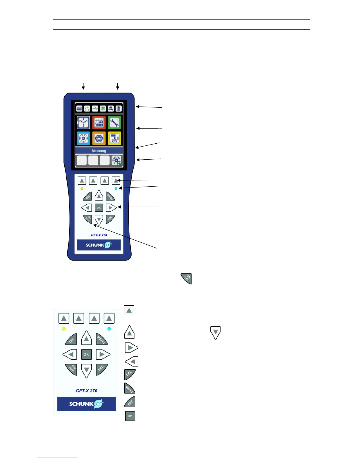
The Handheld Unit is equipped with a high resolution TFT display which shows all important
menu items as icons. These icons, which are self-evidend, and a transparent command
structure allows easy operation also for occasional users.
All items are designated for use in severe workshops, the Handheld Unit is in addition equipped
with a silicon protector and offers therefore utmost protection against shocks and drop down.
4.1 Packing list
When you open the case, please make sure that all parts and components are included in the
Gripping Force Testers GFT®-X 270 M3 / M4 package:
;Handheld Unit GFT®-X 270 with Protector
;Power Supply Plug with USB master-connector
;Adapter for North America, United Kingdom, Australia and Europe
;GFT®-X ChuckExplorer for Windows-XP / Windows 7
(CD contains operating software and operating manual)
;USB- connecting cable from Handheld Unit to PC/Laptop, approximately 1m length
;Measuring Head for jaw chucks with rotating electronics and 4 each of Extension
Cylinder for jaw diameter ø72mm
;3 each Extension Cylinders for jaw diameter ≥88 und ≥108mm
;Torx-key T15 inclusive spare screws
;Stand with magnetic mounting for rpm measurement
;Measuring Head - charging cable, 2 pin, approximately 1m length
;Loading Bracket for Measuring Head
The GFT®-X Upgrade Kit includes following parts:
;Handheld Unit GFT®-X with Protector
;Power Supply Plug with USB master-connector
;Adapter for North America, United Kingdom, Australia and Europe
;GFT®-X ChuckExplorer for Windows-XP / Windows 7
(CD contains operating software and operating manual)
;USB-connection cable from Handheld Unit to PC/Laptop, approximately 1m length
GFT®-X Upgrade Kit can only be used for Measuring Heads showing a serial
number of >= 0089-3.
For other Measuring Heads packing list can vary.

Gripping Force Tester GFT®-X 270 Rev. 1.8/1.5 12/2012 page 7
H.-D. SCHUNK GMBH & CO. SPANNTECHNIK KG Lothringer Straße 23 D-88512 Mengen
Tel. +49-(0)-7572-7614-0 Fax +49-(0)-7572-7614-99 www.schunk.de
5 Overview
Figure: GFT®-X measuring set up
A fundamental distinction is made between stationary and dynamic mode:
Static operation
Measuring Head to be clamped, magnetic mounting for rpm measurement is not
needed
Dynamic operation
Measuring Head to be clamped, the stand for rpm measuring is fastened to the
support of the machine. Now the support must be positioned in such a way that the
magnetic bar ends besides the black cover of the Measuring Head (see chapter
8.3.2)

Gripping Force Tester GFT®-X 270 Rev. 1.8/1.5 12/2012 page 8
H.-D. SCHUNK GMBH & CO. SPANNTECHNIK KG Lothringer Straße 23 D-88512 Mengen
Tel. +49-(0)-7572-7614-0 Fax +49-(0)-7572-7614-99 www.schunk.de
6 Technical Data
6.1 GFT®-X Handheld Unit
Power supply via USB, 5V DC
Measurement range / gripping force F
indication in kN or lbf, selectable by user
bargraph in % full scale, wheras value of
measurement range is indicated as follows:
0.....80% green,
80.…95% yellow,
95...100% red.
Measurement range / speed (rpm) indication in 1/min (can be switched off)
Dimensions 220x100x50mm
Weight 460g
Operating temperature 0...40°C
Protection class IP54
Interface PC / Laptop USB 2.0
Data cable/charging cable Handheld Unit approx. 1,5m length
Charging cable for Measuring Heads approx. 1m length including mating connector
Receiving frequency 433,92 MHz
Distance Handheld Unit / Measuring Head see chapter 6.2 / 6.3
6.2 Measuring Heads for collets
Measuring Head M1 Measuring Head M2
Power supply internal energy storage
Energy storage capacity ca. 1,5h@50% duty cycle
Measurement range/gripping
force F 0...75kN 0...120kN
Measurement range/
speed of rotation (rpm) >approx. 200*)to <10.000 rpm >approx. 200*)to <8.000 rpm
Accuracy (F/rpm) <5% / <1% fsr
Clamping diameter 18mm 42mm
Number of jaws 3 3
Dimensions ø18/57x56mm ø42/57x63mm
Weight 400g 700g
Operating temperature 0...40°C
Protection class IP65
Transmitting frequency 433,92MHz
Charge time <3 minutes
Distance Handheld Unit/
Measuring Head >1m and <4m straight line (value may vary depending on the
ambient conditions)
*) the lower value can start from 60 rpm by reducing the gap between magnet and Measuring
Head from 3mm to about 2mm

Gripping Force Tester GFT®-X 270 Rev. 1.8/1.5 12/2012 page 9
H.-D. SCHUNK GMBH & CO. SPANNTECHNIK KG Lothringer Straße 23 D-88512 Mengen
Tel. +49-(0)-7572-7614-0 Fax +49-(0)-7572-7614-99 www.schunk.de
6.3 Measuring Heads for jaw chucks
Measuring Head M3 Measuring Head M4
Power supply by internal energy storage
Energy storage capacity approx. 1,5h@50% d.c. approx. 1,5h@50% d.c.
Measurement range/gripping
force F 0…180kN (2 jaws)
0…270kN (3 jaws) 0…30kN (2 jaws)
0…45kN (3 jaws)
Measurement range/speed (rpm) >ca. 200*)bis <6.000 rpm
Accuracy (F/rpm) <3% / <1% fsr <1,5% / <1% fsr
Clamping diameter 72…108mm
Number of jaws 2 or 3, user adjustable
Dimensions ø68/57x63mm
Weight 700g without extentions
Operating temperature 0…40°C
Protection class IP65
Transmitting frequency 433,92MHz
Charge time <3 minutes
Distance Handheld Unit/
Measuring Head >1m and <4m straight line (value may vary depending on the
ambient conditions)
*) the lower value can start from 60 rpm by reducing the gap between magnet and Measuring
Head from 3mm to about 2mm
6.4 Mains / Battery operation
The GFT®-X Handheld Unit is supplied by 5VDC (500mA) via a Power Supply Plug with an input
voltage range from 100VAC to 240VAC. Different interchangeable blade assemblies for North
America, United Kingdom, Australia and Europe are included.
Please see chapter 13 for a guidance to exchange the interchangeable blade assemblies.
Furthermore GFT-X is equipped with a powerful battery (Li-Ion). A one time charge allows an
operation up to 5 hours. During this time frame, a Measuring Head can be loaded up to 4 times
out of the Handheld Unit battery.
A correct indication of the charge condition is only possible until the battery is
completely full charged and discharged first. It's recommended to charge the
handheld unit first completely and then use it until the power is turned off
automatically.
Charging condition of the battery is indicated on battery symbol in Status Line, left side (see
chapter 7.3).
Battery could, if not in use and not charged for several months, discharge itself.
If operating time drops down to less than 2 hours it is recommended to replace the
battery (see chapter 15)

Gripping Force Tester GFT®-X 270 Rev. 1.8/1.5 12/2012 page 10
H.-D. SCHUNK GMBH & CO. SPANNTECHNIK KG Lothringer Straße 23 D-88512 Mengen
Tel. +49-(0)-7572-7614-0 Fax +49-(0)-7572-7614-99 www.schunk.de
7 Handheld GFT®-X
7.1 Overview
Measuring Head USB interface/
Power Jack Power Plug
Status Line
Set Menu
Command Line
Display Line for Speed Buttons / Softkeys
Speed Buttons
LED indicator
Key Pad
Powerswitch
7.2 Keyboard GFT®-X Handheld Unit
To switch on and off the Handheld Unit press for about 2 seconds. First it appears the
Welcome Logo, at the same time blue LED twinkles. The Set Menu appears after 2 seconds
automatically.
Speed Button – With this button the above indicated menu
item will be chosen. These buttons are freely configurable
(see chapter 7.4)
Moves icon or line above Moves icon or line down
Moves icon or character / number to the right
Moves icon or character / number to the left
Delete deletes last input (character / number)
Menu Back to Main Menu
ESC Back one level above
OK Confirm selection

Gripping Force Tester GFT®-X 270 Rev. 1.8/1.5 12/2012 page 11
H.-D. SCHUNK GMBH & CO. SPANNTECHNIK KG Lothringer Straße 23 D-88512 Mengen
Tel. +49-(0)-7572-7614-0 Fax +49-(0)-7572-7614-99 www.schunk.de
7.3 Status Line
Explanation of the symbols from left to right:
>80% >50% >10% <10% <10%, <10min (charging condition/remaining time)
Indicates the current charging condition of the integrated Lithium-Ion battery. At a remaining
operating time of less than 10 minutes a pop-up window appears and remembers you to
connect the Handheld Unit to a Power Supply or a PC.
If the charging symbol turns red it is not possible charging the Measuring Head or the charging
process stops.
If an unloaded Measuring Head shows >0kN (offset), tare is possible by pressing in the
menu Measurement.
Deviations >3% (M1 – M3) and >5% (M4) of measurement range couldn´t be compensated.
The Measuring Head should be returned for service.
Meaning of symbol colors:
Green symbol - Measuring Head works fine, no tare applied
Yellow symbol - Measuring Head still works fine, however tare has been applied
Red symbol - Measuring Head for service, offset to large, tare is impossible
Green symbol if PC or Power Supply is attached and connection is fine. Red symbol means no
USB connection.
Blinking green symbol indicates proper radio communication to Measuring Head.
Red symbol indicates disturbed radio communication or no Measuring Head available /in range.
Indicates chosen Measuring Head M1 or M2. At M3 and M4 the number of jaws is also
indicated.

Gripping Force Tester GFT®-X 270 Rev. 1.8/1.5 12/2012 page 12
H.-D. SCHUNK GMBH & CO. SPANNTECHNIK KG Lothringer Straße 23 D-88512 Mengen
Tel. +49-(0)-7572-7614-0 Fax +49-(0)-7572-7614-99 www.schunk.de
Charging condition of Measuring Head, quantitative indication only (shown if measuring head is
switched on).
Tara function always to refers to the dedicated Handheld Unit. If Measuring Head is
tared with different Handheld Units the Measuring Head could be damaged.
The charging condition detection of Handheld Unit is self-learning. It takes several
charging cycles till the charge status is detected properly. First charge is already
made at factory.
7.4 LED indicator
Left and right below the Speed Buttons two LED are located with following meaning:
- While pressing twinkles some times prior to
Welcome Logo appears
- twinkles as soon display turns into Power Save Mode
(display almost dark)
Charge indicator: LED is illuminated during charging is in
progress
7.5 Speed Buttons
The lowermost line of the display is reserved for Softkeys
which can be programmed by the user. The left three Icons
are free to be programmed, whereas the Icon on the right
side is predetermined to charge the Measuring Head.
Setting / programming Speed Buttons
-choose the relevant function
-activate the Icon (triangle on the left and a highlighted
frame)
-press desired Speed Button for about 2 seconds
-the Icon appears in the display
As soon as desired symbol appears in the Speed Button
Bar, the programming is finished successfuly.
The Softkeys could be programmed as often as desired.
Already programmed keys couldn´t be deleted. Only overwriting is possible.
In some Menus not each Softkey is available.

Gripping Force Tester GFT®-X 270 Rev. 1.8/1.5 12/2012 page 13
H.-D. SCHUNK GMBH & CO. SPANNTECHNIK KG Lothringer Straße 23 D-88512 Mengen
Tel. +49-(0)-7572-7614-0 Fax +49-(0)-7572-7614-99 www.schunk.de
7.6 Menu GFT®-X Hand Held - outline
Use the arrow keys for easy navigation on Set menu. By pressing you will end up directly to
the important sub menu.
The chosen or activated Icon will be discovered by a triangle on the left side and a highlighted
frame. A clear explanation is also shown in the Command Line.
The main menu encloses represented icons:
Icon*) Description Further notes
Measurement see chapter 7.6.2
Define new data collection see chapter 7.6.3
Settings see chapter 7.6.4
Menu Measuring Head see chapter 7.6.5
Menu collet chuck see chapter 7.6.6
Select language see chapter 7.6.7
*) All Icons figured as „selected“, identifiable by the white triangle, at the left side of the border.
All functions and Icons are explained in a tree structure on next page, followed by a
detailed description of the relevant commands.

Gripping Force Tester GFT®-X 270 Rev. 1.8/1.5 12/2012 page 14
H.-D. SCHUNK GMBH & CO. SPANNTECHNIK KG Lothringer Straße 23 D-88512 Mengen
Tel. +49-(0)-7572-7614-0 Fax +49-(0)-7572-7614-99 www.schunk.de
7.6.1 Menu-Overview

Gripping Force Tester GFT®-X 270 Rev. 1.8/1.5 12/2012 page 15
H.-D. SCHUNK GMBH & CO. SPANNTECHNIK KG Lothringer Straße 23 D-88512 Mengen
Tel. +49-(0)-7572-7614-0 Fax +49-(0)-7572-7614-99 www.schunk.de
7.6.2 Measuring
Individual measurement for an experimental setup could easily be performed and
displayed with this function. The Measuring Head to be chosen should be desired
and activated under Icon Menu Measuring Head.
If a pop up Windows appears with „No Measuring Head connected!“ make sure that
Measuring Head is switched on (white LED on Measuring Heads front face is
twinkling). Radio communication should also be checked.
7.6.2.1 Measuring Head Recalibration
If the Measuring Head is connected to GFT®-X Handheld
Unit, following message will be shown:
Serial number: x x x x – x
Calibration expires:
When using a new Measuring Head it will give an advice
(see date code) to a label sticked on the Measuring Head.
The sticker shows the date when factory calibration date
expires.
After the first factory recalibration the date of expire will be
shown in a format MM_YYYY like shown in the sample left.
Recalibration should be performed at least every 12
months to guarantee correct function of Measurement
Head.
Version: y_y displays software version of Measuring Head
To be confirmed by pressing OK
The Handheld Unit now shows the current measurement
values. If no load is applied to the Measurement Head and
the indication shows a value >0kN, tare function can be
applied by pressing (see chapter 7.3).
Depending on individual Setting (see chapter 7.6.4) the
force only will be indicated or both force and speed. The
unit for force can be adjusted to kN or lbf (1kN = 0,2248 x
1000lbf).
If needed the Measuring Head can be recharged directly
form this menu by using the relevant Speed Button.
If no Measuring Head is chosen the message No
Measuring Head connected! appears. This window must
be confirmed by pressing OK. Managing all Measurement
Heads must be performed under Menu Measuring Head,
chapter 7.6.5.

Gripping Force Tester GFT®-X 270 Rev. 1.8/1.5 12/2012 page 16
H.-D. SCHUNK GMBH & CO. SPANNTECHNIK KG Lothringer Straße 23 D-88512 Mengen
Tel. +49-(0)-7572-7614-0 Fax +49-(0)-7572-7614-99 www.schunk.de
7.6.2.2 Recharge Measuring Head
This Icon is available independent where you currently are. It allows easy and fast loading of a
linked Measurement Head at any time. Just link the Handheld Unit to the
Measurement Head (switched off) with the Connecting Cable and press the relevant
Speed Button. The message “Measuring head battery charging…” appears. Is the
loading process finished after a few minutes the message “Battery is fully charged”
appears. Both popup windows should be confirmed by
7.6.3 Define new data collection
This function allows the aquisition of up to 20 measurement values and store them
under a user defined name. This data can be processed afterwards by the
ChuckExplorer. This tool allows easy transfer of the data to a PC, showing it on xy
diagram and archive it. The number of stored data to be transferred to a PC is not
limited.
First put in your individual entry. Navigate by using arrow
keys , confirm by corrections to be made by
or back.
iD: up to 10 characters/numbers
Date: use format DayDay_MonthMonth_YearYear
(just use 2 last digits for year, e.g. 11 for 2011
Number: maximum 3 digits, numbers only, range from
1 to 254
Activate save or press the Speed Button floppy disk to memorize your entries. Now
you jump directly to measurement mode. Besides the measurement values the
number of stored measurements are indicated.
Use the arrow keys to navigate to the next entry.
Pressing Disc symbol in the Speed Button all entries are stored and a jump to
measurement mode follows. If window keep staying the same the cursor shows you
an invalid or not complete entry. Please check this line and try again.
If cursor keeps staying on the input mask after save or disk symbol is activated, the
Handheld Unit has recognized an entry error. Please check your entries regarding
this chapter again and use just valid characters.

Gripping Force Tester GFT®-X 270 Rev. 1.8/1.5 12/2012 page 17
H.-D. SCHUNK GMBH & CO. SPANNTECHNIK KG Lothringer Straße 23 D-88512 Mengen
Tel. +49-(0)-7572-7614-0 Fax +49-(0)-7572-7614-99 www.schunk.de
Speed Buttons layout for further actions:
Accept / overtake measured
value
Finish series of measurements
and exit to Set Menu
Delete measured value
Charge Measuring Head (see
chapter 7.6.2.2)
Handheld Unit always stores the last Measurement Head in use. If you switch on the
Handheld Unit after a while you do not have to activate the Measuring Head again.
The serial number will be stored inside the device till a new entry follows.
7.6.4 Settings
Following functions are available in this menu:
Contrast Allows quantitative changing of brightness by pressing
arrow keys left or right, confirmation by OK
Display Indication of measurement values:
force and number of revolutions or force only
Units Force unit to be changed from kN to lbf and v.v.
Screen
saver
Screen saver to be activated after x minutes when no
entries happens.
Time to be set from 1 bis 43 minutes, acceptance of
indicated value by pressing OK.
Reduces brightness to a minimum and helps to increase
operating time. When in Save mode the first entry leads to
normal indication again.

Gripping Force Tester GFT®-X 270 Rev. 1.8/1.5 12/2012 page 18
H.-D. SCHUNK GMBH & CO. SPANNTECHNIK KG Lothringer Straße 23 D-88512 Mengen
Tel. +49-(0)-7572-7614-0 Fax +49-(0)-7572-7614-99 www.schunk.de
7.6.5 Menu Measuring Head
The Gripping Force Tester GFT®-X can operate with different Measuring Heads.
Available are Measuring Heads for jaw chucks and collets. Furthermore, there is a
choice of different clamping forces, dimensions and number of jaws available.
Basically only one Measuring Head can communicate with
Handheld Unit at the same time. However this menu allows
administration of up to eight Measuring Heads. The
activated Measuring Head is marked with a triangle on the
left side of label.
The image on the left shows a Measuring Head with serial
no 0001-1 which is active.
To navigate use the arrow keys, confirm with
The following commands are available:
Choose
Measuring Head Activates the relevant Measuring Head with the
triangle from the index
Add a (new)
Measuring Head A sub menu will open and requires the entry of a new
Measuring Head serial number.
Delete
Measuring Head Deletes the Measuring Head marked
Recharge
Measuring Head see chapter 7.6.2.2

Gripping Force Tester GFT®-X 270 Rev. 1.8/1.5 12/2012 page 19
H.-D. SCHUNK GMBH & CO. SPANNTECHNIK KG Lothringer Straße 23 D-88512 Mengen
Tel. +49-(0)-7572-7614-0 Fax +49-(0)-7572-7614-99 www.schunk.de
7.6.6 Menu collet chuck
This menu refers to chuck jaw Measuring Head only, which serial number ends with
xxxx-3 or xxxx-4. The Measurement Head M3 and M4 offer the choice of 2 or 3
jaws.
The selection of the number of jaws is made with arrow
keys of the keypad. The active choice is indicated with a
white arrow.
For confirmation press .
7.6.7 Select Language
The GFT®-X Handheld Unit is prepared for several languages:
German English
Italian Spanish
Russian Chinese
and Japanese.
The selection is made with the arrow keys and confirmed by .

Gripping Force Tester GFT®-X 270 Rev. 1.8/1.5 12/2012 page 20
8 Measuring Head
There are four different Measuring Heads available for the GFT®-X. Two for collets (M1 and M2)
and two for chucks (M3 and M4)
The Measuring Head works according to the following principle:
Via a dedicated arrangement of strain gauges inside the Measuring Head, the mechanical forces
are converted into an electrical signal which is amplified by the integrated electronics,
transformed into a digital radio signal via a micro-controller and sent to the Handheld Unit. There
the data signal is encoded and displayed.
Factory provided the Measuring Heads are calibrated. After respectively 12 months
a check-up and a recalibration should take place by the manufacturer. The date for
the next calibration is shown under Menu Measurement or marked on the
Measuring Head (see chapter 7.6.2.1).
The maximum load is mentioned on each Measuring Head. Please make sure that
this value will not exceed because this can lead to non valid measurements or even
to the destruction of the Measuring Head.
Please be assured, that prior to measuring procedure the Measuring Head is tight
and plane-parallel clamped to the rotational axis.
8.1 Measuring Head M1 and M2 for collets
Via the 3 contact surfaces (support) on the Measuring Head the force is transmitted to the
measuring elements inside the housing. It is recommended to use special collets with smooth
finish in order to avoid damage to these contact surfaces. Furthermore, care must be taken to
insert the measuring head in such a way that it does not get tilted. The "jaw centre" inscription
must correspond to the centre of one of the three collet jaws. Please note, that compliance with
the above instructions will be decisive for the quality of the measuring values.
Measuring head M1 (max. 75kN)
H.-D. SCHUNK GMBH & CO. SPANNTECHNIK KG Lothringer Straße 23 D-88512 Mengen
Tel. +49-(0)-7572-7614-0 Fax +49-(0)-7572-7614-99 www.schunk.de
support
Table of contents
Other SCHUNK Test Equipment manuals
Popular Test Equipment manuals by other brands

CIRCUIT DESIGN
CIRCUIT DESIGN TB-CDT-TX-01 Operation guide

Micro Movements
Micro Movements M1500 Series user guide

Softing
Softing NetXpert XG2 PLUS quick start guide

Keysight Technologies
Keysight Technologies 85038A 7-16 User's and service guide

Sensidyne
Sensidyne Go-Cal user manual

FALEX
FALEX 400 Operation and maintenance manual