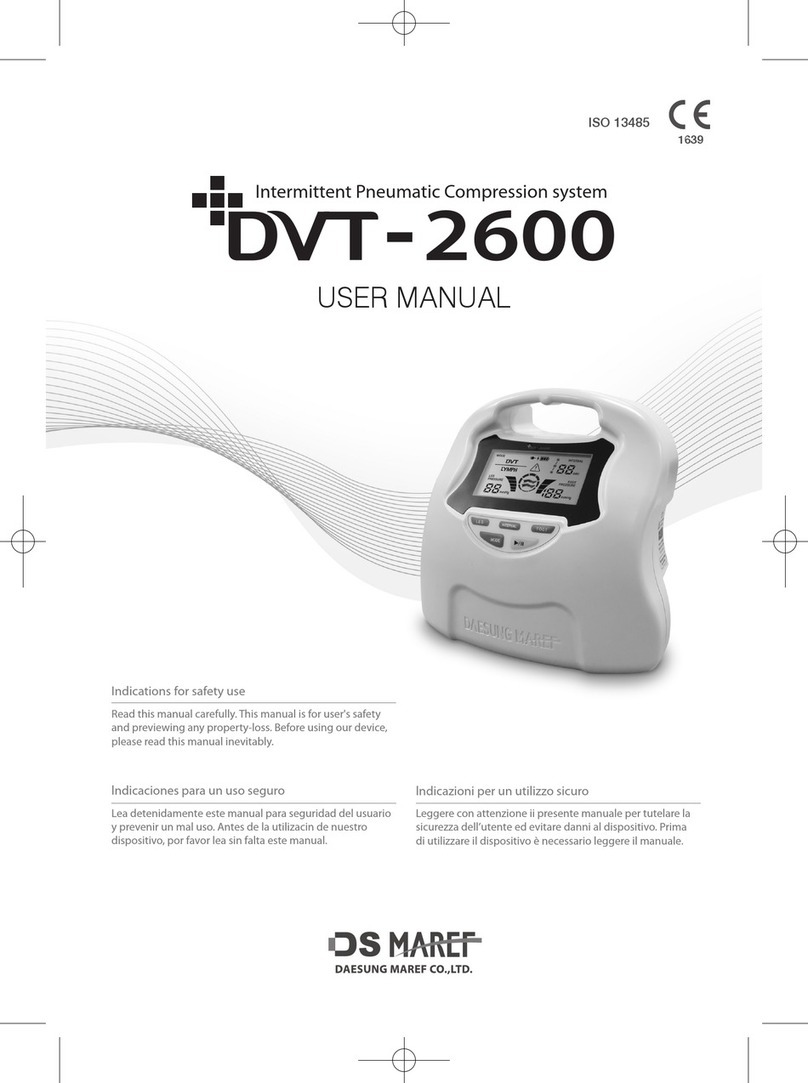
DS Maref DVT-2600 User manual


Page 2
TABLE OF CONTENTS
* Refer to the DVT-2600 User's Manual please.
1. Purpose p.3
2. Scope p.3
3. Directive p.3
4. Term Definitions p.3
5. Related Documents p.3
6. Technical specification p.4
7. Exploded View & Parts Listing p.5
8. Battery replacement method p.7
9. Block diagram p.8
10. Attaching the tubing and user guide p.10
11. Controller Maintenance and test methods p.11
12. Maintenance Check list p.14

Page 3
1. Purpose
- This service manual is provide the replacement method for Service Staff.
2. Scope
- Must using this manual by Service Staff.
- Can’t using this manual USER.
- Application the only DVT-2600.
3. Directive
3-1. Implementation
- The documents is valid as per effective date, previous revision become invalid by that date.
3-2. Requirements Relating to Persons, Performing this Service Manual
- The service on DVT-2600 must be performed by qualified staff. The qualification can be achieved
by professional, experience and acquaintance with relevant technologies, design standards and local
regulations. The electrical part must be performed by certified electrician or electrically trained
person under certified electrician supervision. The service staff assessing the safety shall be able to
recognize possible consequences and risks arising from non-conforming device and materials.
In addition, this device does not requirement the special skill for repair and replacements.
4. Term Definitions
- USER : Using the device by intended use, Our company does not provide the service manual.
- Service Staff : Qualified staff, They can be repair and replacements for device.
Qualified by distributor of each country
- Inspection : Check and test the device by Electrical, Mechanical
- Parts : Electrical, Mechanical parts for Only this device.
- Replacement : Replace the Module, Mechanical parts, Board etc.
- Repair : Repair for Defeat and problem of part. This term does not including the replacement.
5. Related Documents
- RND-R-MUM-102-02 User Manual

Page 4
6. Technical specification
6-1. Device specifications
Items
Specifications
Model Name
DVT-2600
Rated Voltage
AC100-240V, 50/60Hz
Power consumption
90-110VA
Rated Fuse
T3.15A/250V
Setting Pressure
Leg : 20 - 60mmHg ±20mmHg (Unit : 10mmHg)
Foot : 120 - 140mmHg ±20mmHg (Unit : 10mmHg)
Setting Interval
28, 48, 60 sec
Dimension
200(W) X 165(D) X 190(H)mm
Weight
2kg (Only body)
Ingress protecting rating
IPX2
Rated Voltage of Battery & Current
Consumption of Battery
DC 11.25V, 3200mAh
DC 11.25V, 3350mAh

Page 5
7. Exploded View & Parts Listing
7-1. Sub ASM FRONT Parts List
Description
1-1. FRONT_COVER
1-2. KNOB_BUTTON
1-3. SUB_KEY_PCB
Part Number
[60120024]
[60123032]
[5035AP02]
Description
1-4. MAIN_BOARD_LCD
1-5. M3XL6 TT
1-6. WINDOW_SHEET
Part Number
[50352P02]
[40021013]
[7060011]
7-2. Sub ASM FRAME Parts List
Description
2-1. FRAME_MAIN
2-2. SHEET_PLATE
2-3. COVER_PLUG
2-4. RUBBER_HOSE_ELBOW
Part Number
[65125030]
[70600112]
[60128075]
[6A102018]
Description
2-5. SOLENOID
2-6. RUBBER_HOSE
2-7. RUBBER_HOSE_PRESSURE
2-8. M3XL5 S
Part Number
[27105001]
[41006003]
[41006004]
[40051007]
Description
2-9. PUMP
2-10. SPONGE
2-11. RUBBER_VIBRATION
2-12. M4XL10 TP
Part Number
[26512006]
[41004000]
[6A101012]
[40011001]
Description
2-13. RUBBER_HOSE
2-14. RUBBER_HOSE
Part Number
[41006003]
[41006003]

Page 6
7-3. Sub ASM REAR Parts List
Description
3-1. REAR_COVER
3-2. RUBBER_PAD
3-3. SUB_CHARGE_PCB
3-4. INLET
Part Number
[60128076]
[6A105005]
[5035AP02]
[22903003]
Description
3-5. M3XL8 TP
3-6. HOLDER_CODE
3-7. AC_CODE
3-8. M3XL6 TT
Part Number
[40011029]
[60131017]
[23061003]
[40021013]
7-4. DVT-2600 assy Parts List
Description
4-1. SMPS
4-2. M3XL6 S
4-3. STICKER
4-4. LABEL
Part Number
[50353P02]
[40051001]
[70600113]
[72DVT320]
Description
4-5. BATTERY
4-6. RUBBER_PAD
4-7. CAP_BATTERY
4-8. M3XL4 M
Part Number
[B1100024]
[6A105006]
[60128077]
[40045021]
Description
4-9. RUBBER_FOOT
4-10. M3XL6 TT
Part Number
[6A101009]
[40021013]

Page 7
8. Battery replacement method
1) Turn off the product and place it on a flat, stable surface or in a safe place.
2) Remove the screw from the battery cover on the back of the device, open the cover and remove
the used battery.
3) After removing the battery connector, pull out the battery by pulling the strap.
4) Be careful about the direction of the battery connector, insert the battery cover, and tighten the screws.
* Use genuine batteries please.
(When using batteries from other manufacturers, there is a risk of fire due to malfunction or
overheating.)
*If the direction of the connector is reversed, there is a risk of fire due to malfunction or
overheating.

Page 8
9. Block diagram
9-1. Whole System Block Diagram
9-2. PCB diagrams
9-2-1. Main system Layout
9-2-2. Main board layout
1) Main B’D top layout

Page 9
2) Main B’D bottom layout
3) MAIN B’D Removal/Installation
* CAUTION : Use a grounded strap when handling any electronic components.
- The user can’t fix the MAIN BOARD. There will be malfunction or damage if the user fixes it
arbitrarily.
- Please replace the main board in case of BOARD fails.
- Please refer to 3. Assembly view when main board disassembles.
- The installation is in reverse order of disassemble view.
9-3. Power board
9-3-1. Power system layout
9-3-2. Power B’D layout
1) Power B’D top layout

Page 10
2) POWER B’D Removal/Installation
* CAUTION : Use a grounded strap when handling any electronic components.
- The user can’t fix the POWER BOARD. There will be malfunction or damage if the user fixes it
arbitrarily.
- Please replace the power board in case of BOARD fails.
- Please refer to 3. Assembly view when main board disassembles.
- The installation is in reverse order of disassemble view.
10. Attaching the tubing and user guide
- Attach sleeve and calibrated pressure gauge to the controller.
- Set the pressure value to 40mmHg on the controller.
- Check the pressure value visually by turning on the controller.
- Refer below check point of the graph for pressure value.
- The error value of setting pressure is ±15%.
- The standard chamber of setting pressure is 2nd chamber (Middle chamber)
* LEG Sleeve
Setting pressure
1ch
2ch
3ch
40mmHg
45mmHg
(51 ~ 39mmHg)
40mmHg±15%
(46 ~ 34mmHg)
35mmHg
(41 ~ 29mmHg)
* FOOT Sleeve
Setting pressure
1ch
120mmHg
120mmHg±15%
(138 ~ 102mmHg)
Sleeve
Main
controller
Sleeve
Pressure
gauge

Page 11
11. Controller Maintenance and test methods
11-1. Test mode Set-up
When you press 'LEG' and 'MODE' buttons for 2 seconds at the same time, test method mode
including 10 test programs starts. Whenever you press the 'mode' button, the test number is
changed from 1 to 10 and when you press the 'START', you can change the selected value or do
the test. If you want to finish test method, please press 'START' for 3 seconds.
11-2. Test mode table
MODE 1
Check the program version
MODE 2
To remove the lymph mode
MODE 3
Check voltage for charging battery
MODE 4
Check battery voltage
MODE 5
Check pressure sensor or calibration
MODE 6
LCD Test
MODE 7
Solenoid valve test
MODE 8
Pump tset
MODE 9
Battery test
MODE 10
Sleeve leakage test
11-3. Test method
No
MODE
DISPLAY
Description
1
MODE 1
- The version indication of controller’s
software
- Left : MAIN Version
- Right : POWER Version
2
MODE 2
LYMPH MODE can be deleted if DVT
MODE is only used
- When you press “START”. You can
turn on out the ‘LYMPH’ mode.
3
MODE 3
- Check the supply voltage of controller
minimum
average
maximum
14.5V
15.0V
15.5V
- If the supply voltage of controller is
below the minimum voltage, the
recharge may not be completed.

Page 12
4
MODE 4
- Check the current voltage of battery ·
maximum voltage : 12.6V±0.2V
- The battery’s voltage marking is
below , connect AC power and
recharge the battery completely..
5
MODE 5
- Pressure calibration can be operated.
- Start pumping with Manual Pump
manually and check the pressure value
from DVT machine and pressure gauge.
If there is difference between value on
DVT machine and value on Pressure
gauge, check how it different. If the
difference is more than ±15%, then
activate following process. Press the
LEG button to control pressure range
between 40, 80, 120. It will go up
accordingly as the LEG button pressed.
Then Keep doing this process until
make two values are equal. When two
values reach to equal value, press the
INTERVAL button to save the current
value. If error range is more than
10mmHg, the settlement won’t be
saved in the program.
(Sensor shoule be replaced if the error
range is too high.)
6
MODE 6
- All icons are displayed on LCD
- Check the break and unclear display
of letters or icons
7
MODE 7
- Check the condition of Solenoid valve
- The left number indicates the
sequence of solenoid valve.
- The right number indicates the
discharge voltage of solenoid valves

Page 13
while running. ·
Regarding the standard of the
discharge voltage, refer to the below
table.
minimum
average
maximum
18mmHg
23mmHg
28mmHg
8
MODE 8
- Check the performance of the air
pump
- The left number indicates the steps of
pump operation
- The right number indicates the
discharge voltage of pump while
running.
- The discharge voltage is 1 ~
30mmHg
9
MODE 9
- Separate AC Cord from outlet. Press
the Start key to make the battery wear
out. Leave the solenoid and pump
work together and wait until below
12.0V, press the start key to stop the
machine. Connect AC cord the machine
and wait for 10minutes. After
10Minutes, check the battery voltage
whether it went up or not.
10
MODE
10
- Connect the controller, hoses, and
sleeves.
- When press the start key, the air
pump put 100mmHg from the 1
channel on the first sleeve and wait for
10 seconds.
If the pressure after 10 seconds
becomes below 20%, the air leakage
can occur on sleeves.
Controller
Sleeve

Page 14
11-4. Device error test
No
code
Error
test method
1
Sleeve connection
error
- Press start key for 40 seconds to check the condition of
wearing sleeves while the controller is not connecting to
sleeves. The error will occur if the controller doesn’t
recognize the sleeves after 40 seconds.
2
Lower Pressure error
- Remove the sleeve in the normal condition and check the
error after 3 cycles.
3
High Pressure error
- While the controller is running normally, check the error in
the maximum 10 cycles after not allowing the air by
bending of tubing.
12. Maintenance Check list
No.
Classification
Item
Inspection
Pass
Fail
1
Controller
Visual Inspection
Display
Damage, Foreign Substances
2
The control button
Damage, Not pressed
3
Air discharge
Damage
4
The bed hanger
Damage
5
Handle
Damage
6
Labeling
Visual Inspection
Equipment label
Deleted, Blurred, Torn
7
Error sticker
Deleted, Blurred, Torn
8
Quick-guide
Deleted, Blurred, Torn
9
Battery charge-guide
Deleted, Blurred, Torn
10
Power cord
Visual Inspection
Power cord
Cut, Scraped, Pressed
11
Tubing set
Visual Inspection
Tubing set
Torn, Blocked, Damaged
12
Accessories
Visual Inspection
User manual
Visual Inspection
13
Quick guide
Visual Inspection
14
Sleeve manual
Visual Inspection
15
Thigh sleeve
Visual Inspection
16
Calf sleeve
Visual Inspection
17
Boot sleeve
Visual Inspection
18
Foot sleeve
Visual Inspection
19
Pressure Check
[LEG 40mmHg]
1 Chamber - 1ch
45mmHg (39 ~ 51mmHg)
20
1 Chamber - 2ch
40mmHg (46 ~ 34mmHg)
21
1 Chamber - 3ch
35mmHg (41 ~ 29mmHg)
22
2 Chamber - 1ch
45mmHg (39 ~ 51mmHg)
23
2 Chamber - 2ch
40mmHg (46 ~ 34mmHg)
24
2 Chamber - 3ch
35mmHg (41 ~ 29mmHg)
25
Pressure Check
1 Chamber - 1ch
120mmHg

Page 15
26
[FOOT 120mmHg]
2 Chamber - 1ch
(102 ~ 138mmHg)
27
Check the program
version
TEST MODE 1
Visual Inspection
28
Check voltage for
charging battery
TEST MODE 3
Visual Inspection
(14.5V ~ 15.5V)
29
Check battery
voltage
TEST MODE 4
Visual Inspection
(9V ~ 12.6V±0.2)
30
LCD Test
TEST MODE 6
Visual Inspection
31
Solenoid valve test
TEST MODE 7
Visual Inspection
(18mmHg ~ 28mmHg)
32
Pump test
TEST MODE 8
Visual Inspection
(1mmHg ~ 30mmHg)

Page 16
RND-R-MSM-102-03 (Rev.06)
Other manuals for DVT-2600
1
Table of contents
Other DS Maref Medical Equipment manuals
Popular Medical Equipment manuals by other brands

Zeiss
Zeiss GeminiSEM Series instruction manual

Kartsana
Kartsana BRAVA TG-1000 instruction manual

Advanced Instruments
Advanced Instruments Osmo1 Service guide

Synovis
Synovis GEM FlowCoupler Instructions for use

Bay Alarm Medical
Bay Alarm Medical In-Home System Troubleshooting

orfit
orfit HP PRO Instructions for use

Bodypoint
Bodypoint PivotFit SH290 Installation and user instructions

PamMobility
PamMobility SYNAGO 727T0045 Instructions for installation and use

Blatchford
Blatchford SMARTIP4B30 Instructions for use

Orliman
Orliman Manutec Fix Use and maintenance instructions

baxter
baxter artis Operator's manual

Interacoustics
Interacoustics Air Fx Instructions for use