Advanced Instruments Osmo1 User manual
Osmo1™
Single-Sample
Micro-Osmometer
ServiceGuide
133006EN Rev 0

2Osmo1™Single-Sample Micro-Osmometer Service Guide
Copyright and trademarks
© 2018 Advanced Instruments
This user guide is copyrighted by Advanced Instruments with all rights reserved. Under copyright laws, this guide may not
be reproduced in any form, in whole or part, without the prior written consent of Advanced Instruments. The following are
trademarks of Advanced Instruments:
• Osmo1™
• Hot-Line™
• Protinol™
• Clinitrol™
• Renol™
Employees of Advanced Instruments have reviewed this guide thoroughly. Although material contained within is believed
reliable, the accuracy and completeness are not guaranteed or warranted, and are not intended to be representations or
warranties concerning the product described. Screenshots and images included in this manual are for purposes of example
only and may not be an exact match with the screens you see.

3
Osmo1™Single-Sample Micro-Osmometer Service Guide
Contents
Contacting Advanced Instruments..............................5
Supplies, standards & controls .....................................6
Replacement parts ..........................................................7
Safe use..............................................................................8
Foreword.......................................................................... 12
Chapter 1
Osmo1 overview ............................................................. 13
1.1 Front view ..........................................................................................13
1.2 Rear view............................................................................................13
1.3 Mechanical description .................................................................13
1.4 Electrical description.....................................................................14
Chapter 2
Setup................................................................................. 16
2.1 Location requirements..................................................................16
2.2 Loading the printer paper ..........................................................16
2.3 Placing the Micro-Sample Test Kit on the instrument ......17
2.4 Connecting to a network (optional)........................................18
2.5 Powering up the instrument .......................................................18
Chapter 3
Osmo1 user interface .................................................... 19
3.1 Touchscreen ......................................................................................19
3.2 Common screen elements...........................................................19
3.3 Home screen ....................................................................................20
3.4 Main menu.........................................................................................20
3.5 User interface icons........................................................................21
Chapter 4
Calibration .......................................................................22
4.1 Factory calibration......................................................................... 22
4.2 When to recalibrate.......................................................................22
4.3 Calibration procedure................................................................... 22
4.4 Canceling calibration ....................................................................23
Canceling the test in progress .............................................23
Canceling the entire calibration...........................................24
4.5 Calibration errors ...........................................................................24
Chapter 5
Settings ............................................................................25
5.1 Accessing the Settings menu....................................................25
5.2 Logging in to a Settings function ............................................26
5.3 Timing out of a Settings session..............................................26
5.4 Default user accounts...................................................................26
5.5 Setting date and time ................................................................. 27
5.6 Setting language ............................................................................ 27
5.7 Setting up user accounts ............................................................ 27
5.8 Adjusting hardware options.......................................................28
Setting audio options ..............................................................28
Adjusting screen brightness .................................................28
Enabling/disabling the printer .............................................28
Adjusting barcode scanner settings ..................................29
5.9 Adjusting probe resistance.........................................................29
5.10 Establishing controls.....................................................................29
5.11 Setting up LIS communication................................................. 30
Send-results mode................................................................... 30
LIS connection indicator colors.......................................... 30
Configuring the LIS connection.......................................... 30
5.12 Configuring a LAN connection ..................................................31
5.13 Managing the system.....................................................................31
Performing a software/firmware update ..........................31
Exporting and/or clearing Osmo1 databases .................32
5.14 Assigning restrictions...................................................................32
Chapter 6
Diagnostics......................................................................33
6.1 Accessing the Diagnostics menu.............................................33
6.2 A/D ......................................................................................................33
6.3 Consumables....................................................................................34
6.4 Sample probe ..................................................................................35
6.5 Barcode..............................................................................................35
6.6 Events .................................................................................................35
6.7 Printer .................................................................................................36
6.8 LCD ......................................................................................................36
6.9 Solenoid.............................................................................................36

4Osmo1™Single-Sample Micro-Osmometer Service Guide
Chapter 7
Maintenance & service..................................................37
7.1 Maintenance ..................................................................................... 37
Chamber cleaning..................................................................... 37
Solenoid maintenance............................................................. 37
Sampler plunger wire replacement and verification ...39
7.2 Service............................................................................................... 40
Chapter 8
Troubleshooting............................................................. 41
8.1 General errors...................................................................................41
8.2 Errors during calibration ..............................................................41
8.3 Errors during testing......................................................................41
8.4 Electro-mechanical problems ...................................................42
Appendix A
Product specifications................................................. 43
Appendix B
Performance characteristics ...................................... 44
Appendix C
Known limitations......................................................... 45
Appendix D
Regulatory notices ....................................................... 46
Appendix E
Supplemental LIS/LAN information......................... 49
Appendix F
Product disposal and recycling................................. 50
Appendix G
System schematic.......................................................... 51
Appendix H
Osmo1 service log..........................................................52
Appendix I
Replacement procedures............................................ 54

5
Osmo1™Single-Sample Micro-Osmometer Service Guide
Contacting Advanced Instruments
General inquiries
• US or Canada
• Toll free phone: 800-225-4034 from 8:00 AM – 4:30 PM Eastern time
• Fax: 781-320-8181
• Outside the US or Canada:
• Phone: +1 781-320-9000
• Fax: +1 781-320-8181
• Email: info@aicompanies.com
• Web: aicompanies.com
Customer Service/Orders
To order supplies for the Osmo1, contact the Customer Service department.
• US or Canada
• Toll free phone: 800-225-4034 from 8:00 AM – 4:30 PM Eastern time
• Fax: 781-320-3669
• Outside the US or Canada:
• Phone: +1 781-320-9000
• Fax: +1 781-320-3669
• Email: orders@aicompanies.com
Hot-Line™ Technical Service
For any questions or problems related to operation or service, contact the Hot-Line Technical Service department.
• US or Canada
• Toll free phone: 800-225-4034 from 8:00 AM – 4:30 PM Eastern time;
after normal business hours, follow prompts
• Fax: 781-320-0811
• Outside the US or Canada:
• Phone: +1 781-320-9000
• Fax: +1 781-320-0811
• Email: techsupport@aicompanies.com
NOTE: When contacting Advanced Instruments for technical support, please be ready to provide the service technician with
the model and the serial number of the instrument, as well as a general description of the problem. It may be
necessary to perform diagnostic checks during the service call, so please contact us from a telephone that allows you
immediate access to the instrument. A service technician may verbally assist you with making minor repairs, may
provide you with information regarding recommended parts or part numbers, and/or may issue you a Return
Merchandise Authorization (RMA) to ship the instrument to us for factory repairs. The RMA procedure is as follows:
1. Contact Advanced Instruments to obtain an RMA.
2. Pack and ship the instrument in its original carton. Do not include instrument supply items.
3. Pre-pay shipment to the factory. Advanced Instruments cannot accept collect shipments.
4. Insure the shipment or accept the risk of potential damage.

6Osmo1™Single-Sample Micro-Osmometer Service Guide
Supplies, standards & controls
To order supplies, standards, and controls, contact the Advanced Instruments Customer Service Department.
(See “Contacting Advanced Instruments” on page 5.)
General supplies
Item Part Number
Micro-Sample Test Kit (500 sampler tips,
500chamber cleaners, and 1 plunger wire)
133800
Printer Paper (5 rolls) FLA835
20-μL Ease-Eject™ Sampler 3M0825
Replacement Sample Probe 133060R
Osmo1 User Guide USB Drive 133005UG
Service Manual 133006SM
Calibration standards
Item Part Number
50 mOsm/kg Calibration Standard
(ten 2-mL ampules)
3MA005
850 mOsm/kg Calibration Standard
(ten 2-mL ampules)
3MA085
2000 mOsm/kg Calibration Standard
(ten 2-mL ampules)
3MA200
Reference solutions & controls
Item Part Number
Clinitrol™ 290 Reference Solution
(ten 2-mL ampules)
3MA029
Osmolality Linearity Set (5 levels) 3LA028
Protinol™ Protein-Based Serum Controls
(3levels)
3MA028
Renol™ Urine Osmolality Controls (2 levels) 3LA085
Other standards
Item Part Number
100 mOsm/kg Calibration Standard
(ten 5-mL ampules)
3LA011
200 mOsm/kg Calibration Standard
(ten 2-mL ampules)
3MA020
400 mOsm/kg Calibration Standard
(ten 2-mL ampules)
3MA040
500 mOsm/kg Calibration Standard
(ten 5-mL ampules)
3LA051
900 mOsm/kg Calibration Standard
(ten 5-mL ampules)
3LA091
1000 mOsm/kg Calibration Standard
(ten 2-mL ampules)
3MA100
1500 mOsm/kg Calibration Standard
(ten 5-mL ampules)
3LA151
IMPORTANT: Advanced Instruments cannot guarantee
the stated instrument performance specifications and
accuracy of test results unless Advanced Instruments
brand consumables are used with the instrument. Use of
consumables from manufacturers other than Advanced
Instruments is not recommended and may adversely
aect system calibration, performance, operation, and
accuracy of test results.
Sample tips and cleaners are single-use consumables;
sample cross-contamination can occur if sample tips
and cleaners are re-used.
For information on obtaining these standards and
controls, contact Advanced Instruments. (See
“Contacting Advanced Instruments” on page5).

7
Osmo1™Single-Sample Micro-Osmometer Service Guide
Replacement parts
To order replacement parts, contact the Advanced Instruments Customer Service Department.
(See “Contacting Advanced Instruments” on page 5.)
NOTE: The replacement procedures referenced below are provided in Appendix I.
Item Part Number Replacement Procedure
Barcode Scanner 133020R 133020PM
LCD Screen Mounting Assembly 133022R 133022PM
Cradle Switch 133023R 133023PM
Control PCB 133037PCR 133037PCPM
Block Probe 133058R 133058PM
Block Probe Cable 133059R 133059PM
Sample Probe 133060R 133060PM
Sample Probe Cable 133061R 133061PM
Cooling Fan Assembly 133062R 133062PM
Power Supply 133063R 133063PM
Power Entry Module 133064R 133064PM
Thermal Printer 133065R 133065PM
RFID Reader 133066R 133066PM
Fuses (two required) 133072R 133072PM
Sample Handling Assembly 133300R 133300PM
Cooling Assembly 133310R 133310PM
Cradle Switch 133076R 133076PM
IMPORTANT: Advanced Instruments cannot guarantee the stated
instrument performance specifications and accuracy of test results unless
the instrument is serviced with factory-specified parts. For information on
obtaining these replacement parts, contact Advanced Instruments. (See
“Contacting Advanced Instruments” on page5).

8Osmo1™Single-Sample Micro-Osmometer Service Guide
Safe use
WARNING: To reduce the risk of bodily injury, electric shock, fire, and damage to the instrument, please read and observe
all precautions in this User Guide.
Only operate this product in accordance with the equipment design, operating instructions, and manufacturer
recommendations; to do otherwise may impair the instrument function or create a safety hazard.
Do not attempt to perform electrical work if you are not fully qualified. This manual is not a substitute for electrical
training.
General cautions
• Only power this instrument with the source specified
on the product electrical ratings label. Refer to the
installation instructions.
• If the power cord provided is replaced for any reason
or if an alternate cord is used, the cord must be
approved for use in the local country. The power cord
must be approved for the product’s listed operating
voltage and must be rated at least 20% greater than
the volt-ampere (VA) ratings marked on the product’s
electrical ratings label. The cord end that connects to
the product must have an IEC 60320 connector.
• Plug the product into an approved grounded electrical
outlet. Exposure to AC voltage could lead to electric
shock, burn, or electrocution. Please be aware of any
exposure of AC voltage in the power cord.
• Do not disable the power cord grounding pin.
• If an extension cord or power strip is used, make sure
that the cord or strip is rated for the product and that
the total ampere ratings of all products plugged into
the extension cord or strip do not exceed 80% of the
cord or strip rating limit.
• Route power cords so that they will not be walked on,
tripped on, or pinched by items placed upon or
against them. Pay particular attention to the plug,
electrical outlet, and the point where the cord exits the
product.
• Do not pull on cords and cables; grasp the
corresponding connector to unplug it.
• Do not install or use this product in any area subject to
extreme short-term temperature variations, or in
locations that exceed the specified operating
environment temperatures.
• Never use this product in a wet area.
• To avoid injury or fire hazard, do not operate this
product in an explosive atmosphere.
• Do not install or use the product on an unstable,
non-level work surface.
• Do not operate this product with the covers removed
or unsecured.

Safe use
9
Osmo1™Single-Sample Micro-Osmometer Service Guide
Service & maintenance cautions
• Unplug the power cord before opening or removing
the covers; otherwise, you may be exposed to electric
shock, excessive temperatures, or mechanical hazards.
• Performing service or maintenance not detailed in the
User’s Guide, with or without this Service Manual,
should only be conducted by a qualified service
technician.
• Never restrict airflow into or out of the product. Check
the air vents for blockages periodically.
• Wipe the exterior of the product with a soft, damp
cloth as needed. Using cleaning products other than
those specified may discolor or damage the finish.
• A discharge of static electricity from contact with the
human body or another conductor may damage
system boards or static sensitive devices. Never
perform internal maintenance without following
recommended static protection procedures.
• The product is equipped with operator accessible
fuses. If a fuse blows, it may be due to a power surge
or the failure of a component. Replace the fuse one
time only. If the fuse blows a second time, it is
probably due to the failure of a component part and
all additional service requirements should be referred
to a qualified technician. Always replace the fuse with
one of the same rating, voltage, and type. Never
replace the fuse with one of a higher current rating.
• If the product requires service for any of the following
reasons, unplug the product from the electrical outlet
and request assistance from a qualified service
technician:
• The power cord, extension cord, power strip, or
power input module is damaged.
• Liquid has been spilled into the interior of the
product.
• A foreign object has fallen into the product.
• The product has been dropped or damaged by a
falling object.
• There are noticeable signs of overheating or a
burning odor.
• The product does not operate normally when you
follow the operating procedures.
• The main supply fuse(s) or any internal fuse(s)
continually fail.
• When servicing the product, use only factory-specified
parts.
• To avoid injury or fire hazard, do not operate this
product in an explosive atmosphere.
• Use caution and appropriate personal protective
equipment (PPE) if you must put your hands inside the
osmometer. Placing hands into the opening could
result in skin punctures or other injuries.
Hazardous Material warnings
• WARNING: Handle all biohazardous materials
according to established good laboratory practices
and follow your institution’s exposure control plan.
Persons handling blood and body fluid samples must
be trained in blood-borne hazards and should observe
Universal Precautions for Preventing Transmission of
Bloodborne Infections as defined by the Centers for
Disease Control and Prevention (CDC). The Universal
Precautions guideline provides infection control by
treating all blood and body fluids as if known to be
infectious. Use personal protective equipment such as
gloves, gowns, etc., to prevent exposure. Store
biohazardous materials in regulated waste containers
and dispose of these materials in a safe and
acceptable manner that is in compliance with all
country, state, and local requirements.
• WARNING: When returning this product for service, or
shipping this product to a second location, remove all
hazardous specimens and decontaminate the product
before packaging it for shipment. If the product
cannot be decontaminated, consult with your shipping
agent for instructions on appropriate packaging and
marking.
• WARNING: If a biohazardous material is spilled on or
inside the equipment, decontaminate the equipment
using a 1% bleach solution or as outlined by those
policies and procedures established within your
institution.

Safe use
10 Osmo1™Single-Sample Micro-Osmometer Service Guide
Symbol conventions
The list of symbols below is for reference only. Some symbols shown below might not appear on the instrument or in the
accompanying documentation.
Symbol Description
This symbol alerts the user to the presence of important operating and maintenance (servicing) instructions.
This symbol alerts the user to the presence of uninsulated dangerous voltage inside the enclosure that may
constitute risk of electric shock to persons.
This symbol alerts the user to the presence of internal components that could be damaged by static electricity.
This symbol alerts the user to the presence of biological substances that may pose a threat to the health of living
organisms, primarily that of humans.
This symbol indicates potential puncture hazards; users keep hands clear.
This symbol alerts the user to the presence of a specific component that could be damaged by static electricity.
This symbol indicates the presence of alternating current (AC).
This symbol indicates the presence of a fuse.
This symbol indicates the presence of protective earth ground.
This symbol indicates the power is ON.
This symbol indicates the power is OFF.

Safe use
11
Osmo1™Single-Sample Micro-Osmometer Service Guide
FCC Statement
WARNING: Changes or modifications to this unit not
expressly approved by the party responsible for
compliance could void the user’s authority to operate the
equipment.
This equipment has been tested and found to comply
with the limits for a Class A digital device, pursuant to
Part 15 of the FCC Rules. These limits are designed to
provide reasonable protection against harmful
interference when the equipment is operated in a
commercial environment. This equipment generates,
uses, and can radiate radio frequency energy and, if not
installed and used in accordance with the instruction
manual, may cause harmful interference to radio
communications. Operation of this equipment in a
residential area is likely to cause harmful interference in
which case the user will be required to correct the
interference at his own expense.
Industry Canada Statement
CAUTION: Any changes or modifications not expressly
approved by the party responsible for compliance could
void the user’s authority to operate the equipment.
ATTENTION: Tout changement ou modification non
expressément approuvé par la partie responsable de la
conformité pourrait annuler l’autorisation de l’utilisateur
d’utiliser l’équipement.
This device complies with Industry Canada license-
exempt RSS standard(s). Operation is subject to the
following two conditions: (1) This device may not cause
interference, and (2) this device must accept any
interference, including interference that may cause
undesired operation of the device.
Le présent appareil est conforme aux CNR d’Industrie
Canada applicables aux appareils radio exempts de
licence. L’exploitation est autorisée aux deux conditions
suivantes: (1) l’appareil ne doit pas produire de
brouillage, et (2) l’utilisateur de l’appareil doit accepter
tout brouillage radioélectrique subi, même si le
brouillage est susceptible d’en compromettre le
fonctionnement.

12 Osmo1™Single-Sample Micro-Osmometer Service Guide
Foreword
About this instrument
Advanced Instruments osmometers use the technique of freezing point depression to measure osmolality. Osmolality is the
total solute concentration of an aqueous solution. Osmometers measure the number of solute particles irrespective of
molecular weight or ionic charge.
Osmolality information is useful to disciplines including but not limited to:
• Clinical, emergency, and sports medicine
• Medical research
• Academic research
Osmolality is a valuable clinical tool used in the diagnosis and treatment of patients. It is a quick and eective test to help
evaluate the body’s water balance or its ability to produce and concentrate urine, to investigate low sodium levels
(hyponatremia), to detect the presence of toxins in the body, and to monitor osmotically active drug therapies such as
mannitol, which is used to treat cerebral edema. This test is also ordered to help monitor the eectiveness of a treatment
for a condition found to be adversely aecting a person’s osmolality.
Osmometers test virtually any biological fluid including but not limited to:
• Whole blood
• Serum
• Plasma
• Urine
• Feces
• Sweat
• Tissue homogenate
Operation of the instrument is deemed moderate complexity under CLIA and FDA guidelines.
About the Service Manual
This Service Manual contains:
• Instructions for performing repairs
• Guides for troubleshooting operational and mechanical problems
• Circuit system illustrations
• Information about replacement parts and service repairs
This manual is designed to assist service technicians and does not imply a license to perform repairs without proper
qualifications.
13
Osmo1™Single-Sample Micro-Osmometer Service Guide
Chapter 1
Osmo1 overview
This chapter provides a general description of the Osmo1
components and its mechanical and electrical operation.
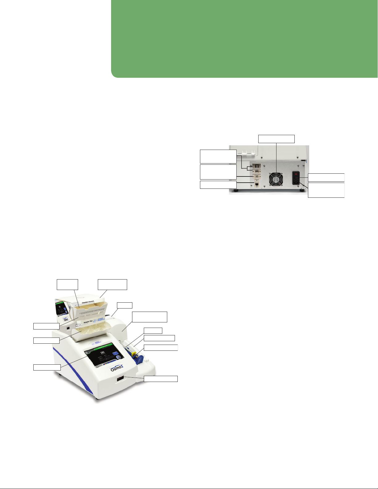
1.1 Front view
Figure 1 shows a front view of the Osmo1 and identifies
its major components:
• Sampler
• Sampler holder (a convenient resting place for the
sampler when it is not in use)
• Operating cradle
• Cooling chamber (inside)
• Touchscreen
• Barcode scanner
• Printer
• Micro-Sample Test Kit (contains 500 chamber
cleaners, 500 sampler tips, and one plunger wire)
Printer
Cooling chamber
(inside)
Sampler
Chamber
cleaners
Operating cradle
Barcode scanner
Micro-Sample
Test Kit
Plunger wire
Sampler tips
Touchscreen
Sampler holder
Figure 1: Osmo1 front view
1.2 Rear view
Figure 2 shows a rear view of the Osmo1.
Power switch
USB 2.0
Type B port
Ethernet port Plug for
power cord
USB 2.0
Type A port
Exhaust fan
Figure 2: Osmo1 rear view--
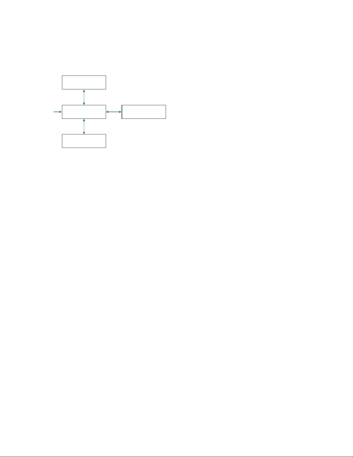
1.3 Mechanical description
Mechanically, the Osmo1 contains four major
components (Figure 3 on page 14):
• Sample Handling Assembly: This module is the part of
the osmometer where testing is performed. The
sample probe, cooling assembly, and actuator switch
are monitored and controlled by the sample handling
assembly.
• Power Supply & Control Assembly: This component
provides power to the instrument via the fused power
inlet assembly. The Control PCB contains the logic
necessary to perform osmometer tests and manage
communications with the display assembly, printer,
and barcode scanner. The physical USB and Ethernet
ports are mounted to the power supply & controls
assembly and connected to the display assembly with
cables.
• Display Assembly: This assembly consists of the
display PCB and the touchscreen display. It provides
the graphical user interface (GUI) used to show and
retrieve information about tests and the instrument’s
set-up. The USB and Ethernet port interfaces and
cables are part of the display assembly.
• Printer: The printer generates copies of test results,
test statistics, and basic information about the
instrument, such as the serial number, date and time,
and software and firmware versions.
Chapter 1 Osmo1 overview
14 Osmo1™Single-Sample Micro-Osmometer Service Guide
Thermal Printer
Power Supply &
Controls Assembly
Osmometer Module
Display Assembly
110–2
40 VAC
50/60 Hz
Figure 3: Mechanical components of Osmo1
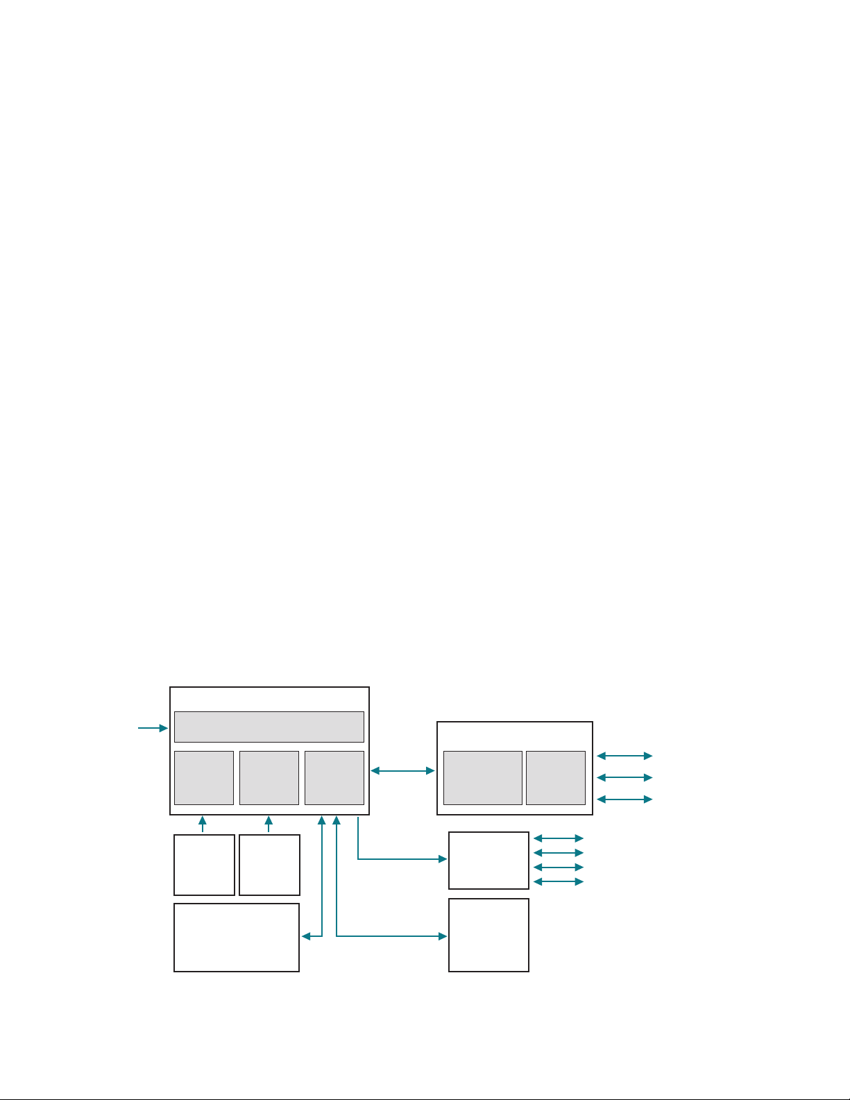
1.4 Electrical description
This section describes the major electrical components
in the Osmo1 (Figure 4 on page 15).
Power supply & control PCB assembly (p/n 133028)
The power supply & control PCB assembly is divided into
lower and upper sections using a metal shelf.
• The lower section contains the power entry module
(PEM), a 200W AC/DC power supply, and a fan. All
high-voltage connections are contained in the lower
section, making it safe to operate the instrument with
either the rear door and/or cover removed.
• The upper section contains the control PCB
(p/n133037PC). This board controls all of the
instrument’s low-level, time-sensitive operations, such
as the thermo-electric chamber, solenoid, thermal
printer, barcode scanner, and high-precision
temperature probes. The control board uses the
PIC32MZ microchip micro-controller.
Barcode scanner port
This port communicates to a 2D barcode scanner
(Diamond Technologies DSE0450-DTC0E) via 115 Kbps,
1start bit, 1 stop bit, and no parity protocol. The
scanner’s presentation mode activates when an object
trips the scanner’s proximity sensor. The sensor has
built-in red illumination LEDs to help read barcodes in
low light conditions.
Thermal printer port
This port communicates to a thermal printer module
(Seiko DPU-D3-00A-E) via 115 Kbps, 1 start bit, 1 stop bit,
and no parity protocol.
RS-232 driver circuits
The instrument uses three RS-232 ports:
• Communication to display PCB
• Communication to scanner
• Communication to printer
A transceiver IC handles the level translation of all three
ports.
Sample cooling assembly circuits
The sample cooling assembly circuit PCB controls the
following:
• TEC cooling block
• Two fans used to exhaust air from the power box and
remove heat from the TEC module
• Activation of the solenoid for sample nucleation
• A/D readings of the Wheatstone bridge circuits of the
sample probe and block probe
Display assembly (p/n 133022)
The display assembly functions as the main user
interface controller and provides connectivity to the USB
and Ethernet peripherals. It contains the display PCB and
color LCD screen, resistive touch element, and the USB/
Ethernet extension cables. The assembly is secured
underneath the top of the instrument’s bezel cover.
7" Color/touch LCD screen
The Osmo1 instrument has a 7" WVGA (800 x 480)
LCD/touch screen built into the display assembly. It uses
a metal gasket to reduce radiated electrical emissions.
The LCD screen has a built-in four-wire resistive touch
screen overlay.
Chapter 1 Osmo1 overview
15
Osmo1™Single-Sample Micro-Osmometer Service Guide
Display PCB
The display PCB contains a high-power IMX6 micro-
processor running a real-time operating system (RTOS)
from Mentor Graphics called “Nucleus.” It is used to
interact with the color/touch LCD screen and to provide
the following serial interfaces to the control PCB:
• Two USB 2.0 Type A ports
• One Ethernet port
• One USB 2.0 Type B port
Interfaces
The display PCB has the following interfaces:
• RS-232 (1x): This serial interface communicates
commands and data to/from the control PCB.
• USB 2.0 Type A (2x): These interfaces allow a USB
device to be attached to the rear of the instrument via
internal shielded USB cables to USB adapter.
• USB 2.0 Type B (1x): This interface allows a USB device
to be attached to the rear of the instrument via
internal shielded USB cable to USB adapter.
• Ethernet (1x): This interface allows a 10/100 RJ45
cable to attach to the rear of the instrument via
internal shielded Ethernet cable to Ethernet adapter.
Non-volatile memory
The display PCB has non-volatile memory used to store
the last one thousand sample records.
The control PCB has non-volatile memory used to store
instrument set-up, calibration, and other pertinent data.
Real-time clock
The display PCB has a real-time clock and a back-up
battery to maintain the date, time, and firmware versions.
The instrument uses three proximity sensors to
determine the presence of sample tubes, objects near
the barcode scanner, thermoelectric module cooling,
activation of the solenoid, and the A/D reading of the
Wheatstone bridge circuits of the sample probe and
block probe.
Cradle switch assembly
The cradle switch is part of the sample handling
assembly. It informs the processor whether the cradle is
fully inserted or is pulled back.
RFID assembly
The RFID assembly reads and updates the count of
sample tips in the test kit box (part no. 133800) and
allows test to begin when count is greater than zero.
110V
/220V
Power In
Serial 3 – USB A Ports
2 – Temperature Probes (2
4-bit)
1 – TEC Cooler
1 – Solenoid Impactor
1 – Cooling Fan
1 – USB B Port
1 – Ethernet Port
AC/DC
Power
Supply
Exhaust
Fan
Control
PCB
Power Entry Module
(Switch, Fused, Filtered)
Power/Control Box
Color/Touch
Display
Display
PCB
Display Box
Cradle
Switch
Assembly
Sample
Cooling
Assembly
RFID Assembly
Barcode
Scanner
Thermal
Printer
Figure 4: Electrical components of Osmo1
16 Osmo1™Single-Sample Micro-Osmometer Service Guide
Chapter 2
Setup
This chapter describes how to set up the Osmo1
instrument in the laboratory.
2.1 Location requirements
The location of the Osmo1 must meet the following
space and electrical requirements.
Osmo1 dimensions
• Not including Micro-Sample Test Kit:
15" D x 14" W x 10" H
(38 cm D x 36 cm W x 25 cm H)
• Including Micro-Sample Test Kit:
15" D x 14" W x 15" H
(38 cm D x 36 cm W x 38 cm H)
Recommended clearance
Allow 6 inches (15 cm) of clear space on each side of the
instrument.
Do not block the exhaust fan airflow on the back panel
or underneath the instrument.
Electrical requirements
Your instrument must be located within five
feet of a properly grounded, three-prong
electrical outlet capable of continuously
supplying 0.5 amperes at 100–240 VAC
(50–60Hz).
If the instrument is not grounded properly, its
operation may be impaired and a safety hazard
may exist. Verify that the outlet is appropriate
before operating the instrument.
Do not disable the grounding plug.
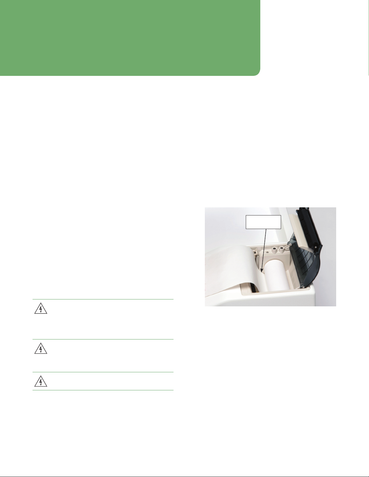
2.2 Loading the printer paper
To prepare the instrument for use, install one roll of
paper as directed below.
1. Lift to open the printer door located on the top right
of the instrument.
2. Unroll 4-6” (15-20 cm) of thermal paper from the roll.
3. Hold the roll so that the paper feeds upwards from
the bottom of the roll towards the front of the
instrument, and place the roll into the printer
(Figure 5).
Feed paper
from bottom
Figure 5: Printer paper roll orientation, door open

Chapter 2 Setup
17
Osmo1™Single-Sample Micro-Osmometer Service Guide
4. Gently close the printer door with the unrolled paper
end outside the printer slot (Figure 6). The door
snaps closed.
NOTE: After the paper roll is installed, always use the
paper-advance button indicated in Figure 6 to
feed the paper through the printer rollers.
Pulling on the paper can damage the printer.
The instrument must be powered on for the
paper-advance button to work. (See
“Powering up the instrument” on page18.)
Paper-advance button
Figure 6: Printer paper loaded, door closed
2.3 Placing the Micro-Sample Test Kit on the
instrument
The Micro-Sample Test Kit contains a supply of
consumables required for testing: 500 chamber cleaners,
500 sampler tips, and one plunger wire.
A Micro-Sample Test Kit must be in place on the top left
of the instrument before testing can begin. As shown in
Figure 7, the box must be oriented so that:
• The photo of the instrument and the box label are
toward the back.
• The dispensing flaps for the chamber cleaners and
sampling tips are toward the front.
If a Micro-Sample Test Kit is not in place on the
instrument when you attempt to run a test, you will
receive the error, “AI consumable box not detected.”
Figure 7: Micro-Sample Test Kit in correct position to begin testing
Chapter 2 Setup
18 Osmo1™Single-Sample Micro-Osmometer Service Guide
2.4 Connecting to a network (optional)
To connect the Osmo1 to a laboratory information
system (LIS) and/or to a local area network (LAN), plug
an Ethernet cable that connects to the network into the
Ethernet port on the back of the Osmo1 unit (Figure 2 on
page13).
NOTE: You must also configure the communication
settings in the Osmo1 software. For more
information, see “Setting up LIS communication”
on page30 and “Configuring a LAN
connection” on page31.
2.5 Powering up the instrument
1. Connect the power cord to the back of the
instrument (Figure 2 on page13) and insert the
plug into the power outlet.
2. Power on the instrument using the rocker switch on
the back.
NOTE: Press the side marked with the symbol
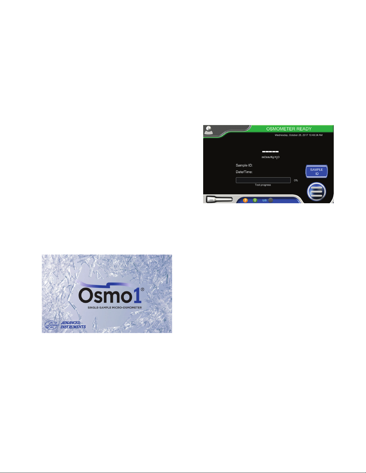
When the unit powers up, the Welcome screen
displays (Figure 8).
Figure 8: Osmo1 Welcome screen
3. After a few moments, the Osmo1 Home screen
displays (Figure 9).
From the Home screen, you can initiate sample
testing and view the results. Initially, the instrument
status shown in the green status banner is
Osmometer Ready.
Figure 9: Osmo1 Home screen

19
Osmo1™Single-Sample Micro-Osmometer Service Guide
Chapter 3
Osmo1 user interface
This chapter describes elements and icons that appear in
the Osmo1 user interface.
3.1 Touchscreen
The Osmo1 provides a touchscreen on the front of the
instrument where you interact with the unit (Figure 10).
From there, you can set parameters, enter commands,
view data, and perform other Osmo1 functions.
Touchscreen
Figure 10: Osmo1 touchscreen
To use the touchscreen, gently tap your selection using
the tip of your finger. Avoid tapping with the flat of your
finger; the screen is designed to read gentle finger
pressure.
CAUTION: Never use sharp objects, fingernails, pens,
pencils, or anything that would leave a mark on the
screen or damage it.
3.2 Common screen elements
Table 1 lists elements that appear on many screens.
Item Description/Use
Status indicator:
• Green: Normal operation
• Red: System error condition
• Yellow: Test in progress
• Orange: IDs required
Current date and time
Sampler-tip status:
• White: Displays number of
sampler tips remaining in box
(while count is 50 or higher).
• Yellow: Displays “<50” when
the number of sampler tips
remaining is less than 50.
System tray may contain:
• Legend of LIS connection
colors
• Assistance contact info
• Message alert
Tap icon to display contents.
Tap to display the Home screen
(not displayed on the Home
screen)
Table 1: Common screen elements
Chapter 3 Osmo1 user interface
20 Osmo1™Single-Sample Micro-Osmometer Service Guide
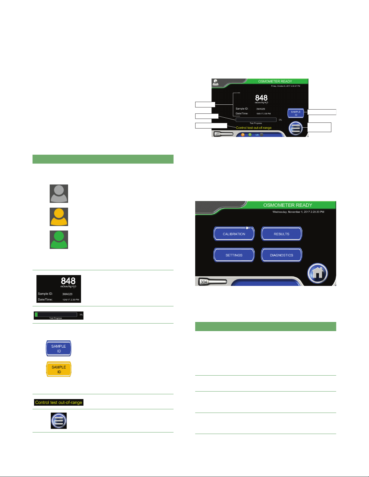
3.3 Home screen
The Home screen is the screen where you perform
sample testing.
Table 2 lists interface elements that are specific to the
Home screen. Figure 11 shows the location of these
elements on the display.
NOTE: The Home screen goes dim after 10 minutes of
inactivity. If a user was logged in to the Home
screen, the system logs out that user.
Item Description/Use
Login button
NOTE: The color of the Login button
indicates the login status:
• Gray: No one is logged in.
• Orange: No one is logged in; login
is required to begin testing. (See
“Assigning restrictions” on
page33.)
• Green: A user is logged in. The
username displays next to the
icon.
To log in: Tap the Login button (gray
or orange) to display the user list.
Then select your username from the
list and enter your password.
To log out: Tap the (green) Login
button.
Latest test sample osmolality
reading, sample ID, date and time of
last test
Test progress bar
Sample ID button
Tap the button to display a keyboard
and activate the barcode scanner;
then use the keyboard or barcode
scanner to enter the sampleID.
NOTE: The color of the button
indicates the Sample ID status:
• Blue: Sample ID is optional.
• Orange: Sample ID is required.
(See “Assigning restrictions” on
page33.)
Example of a warning message
Tap to display the Main menu
Table 2: Items on the Home screen
Enter sample ID
Display Main
menu
Progress bar
Warning message
Latest test
Figure 11: Home screen elements
3.4 Main menu
The Main menu (Figure 12) provides a button for each
user interface section: Calibration, Results, Settings, and
Diagnostics.
Figure 12: Osmo1 Main menu
Table 3 provides an overview of each section.
Function Description/Use
Calibration Displays the Calibration screen; see Chapter 4
on page22 for details.
NOTE: The Osmo1 has been calibrated at the
factory. However, you should recalibrate it in
certain circumstances. See “When to
recalibrate” on page22 for more
information.
Results Displays a list of test results; refer to the
Osmo1 User Guide (133005UG) for details.
Settings Displays the Settings menu for access to
configuration options; see Chapter 5 on
page25 for details.
Diagnostics Displays the Diagnostics menu for access to
system tests and performance data; see
Chapter 6 on page33 for details.
Table 3: Main menu buttons
Other manuals for Osmo1
1
Table of contents
Other Advanced Instruments Medical Equipment manuals

Advanced Instruments
Advanced Instruments Anoxomat Mark II CTS User manual

Advanced Instruments
Advanced Instruments Osmo1 User manual

Advanced Instruments
Advanced Instruments OsmoTECH XT User manual

Advanced Instruments
Advanced Instruments 3900 User manual

Advanced Instruments
Advanced Instruments Anoxomat III User manual

Advanced Instruments
Advanced Instruments 3250 User manual

Advanced Instruments
Advanced Instruments OsmoPRO Multi-Sample User manual

Advanced Instruments
Advanced Instruments OsmoTECH User manual

Advanced Instruments
Advanced Instruments OsmoTECH XT User manual

Advanced Instruments
Advanced Instruments OsmoTECH PRO User manual


