3
READ BEFORE INSTALLATION
1. Be sure to carefully read and understand the
instructions before attempting to install these speakers.
2. For safety, disconnect the negative battery terminal
from the battery prior to beginning the installation.
3. For easier assembly, we suggest you run all wires prior
to mounting speakers in place, also have all your tools
athand: drill, set of Allen keys, crimpers, soldering iron,
wire strippers, heat shrink tubing, etc.
4. Use high quality connectors for a reliable installation
and to minimize signal or power loss.
5. Think before you drill! Be careful not to cut or drill into
gas tanks, fuel lines, brake or hydraulic lines, vacuum lines
or electrical wiring when working on any vehicle. If
installation in a boat, take care not to cut or drill through
the main hull.
6. Never place cables near fuel lines or power (if possible),
also never run wires underneath the vehicle, running the
wires inside the vehicle or hull area provides the best
protection.
7. Avoid running wires over or through sharp edges, use
rubber or plastic grommets to protect any wires routed
through metal, especially the firewall.
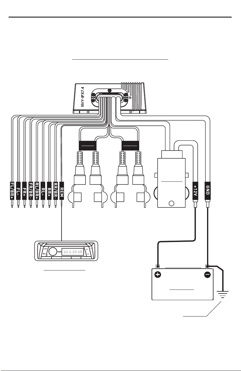
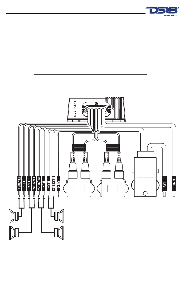
AMPLIFIER INSTALLATION
Amplifiers are generally mounted in closed
compartments of the vehicle or watercrafts.
Select a location that will provide adequate
ventilation for the amplifier. Avoid mounting the
amplifier in exposed areas.
Secure the amplifier with the screws provided.
Before securing the amplifier, inspect the
mounting location carefully to ensure that you do
not drill into or damage any electrical, hydraulic,
fluid, or fuel lines.
1. Before you start, disconnect the negative cable
from the battery, tape up the end so it is isolated
from the battery.
2. Run an appropriate gauge wire from the battery
to the amplifier. Plan this part of the installation
carefully. this cable will carry very high current. If
it should short to the body and it is not properly
fused, it could catch fire.
3. Connect the power wire to the battery using a
fuse capable of the total current load of all
amplifiers connected. Wait until the end locate the
fuse as close as possible to the battery.
LEER ANTES DE INSTALAR
1. Asegúrese de leer detenidamente y comprender las
instrucciones antes de intentar instalar estos altavoces.
2. Por seguridad, desconecte el terminal negativo de la
batería antes de comenzar la instalación.
3. Para facilitar el montaje, le sugerimos que pase todos los
cables antes de montar los altavoces en su lugar, también
tenga a mano todas sus herramientas: taladro, juego de
llaves Allen, engarzadoras, soldador, pelacables, tubo
termorretráctil, etc.
4. Use conectores de alta calidad para una instalación
confiable y para minimizar la pérdida de señal o energía.
5. ¡Piense antes de taladrar! Tenga cuidado de no cortar ni
perforar los tanques de gasolina, las líneas de combustible,
las líneas hidráulicas o de frenos, las líneas de vacío o el
cableado eléctrico cuando trabaje en cualquier vehículo. Si
se instala en un barco, tenga cuidado de no cortar ni
perforar el casco principal.
6. Nunca coloque cables cerca de líneas de combustible o
energía (si es posible), tampoco pase cables debajo del
vehículo, pasar los cables dentro del vehículo o área del
casco brinda la mejor protección.
7. Evite pasar cables sobre o a través de bordes afilados,
use ojales de goma o plástico para proteger cualquier cable
que pase a través de metal, especialmente en el
cortafuegos.
INSTALACIÓN DE AMPLIFICADOR
Los amplificadores generalmente se montan en
compartimentos cerrados del vehículo o
embarcaciones. Seleccione una ubicación que
proporcione una ventilación adecuada para el
amplificador. Evite montar el amplificador en áreas
expuestas.
Asegure el amplificador con los tornillos
proporcionados. Antes de asegurar el amplificador,
inspeccione cuidadosamente la ubicación de montaje
para asegurarse de no perforar ni dañar ninguna
línea eléctrica, hidráulica, de fluido o de combustible.
1. Antes de comenzar, desconecte el cable negativo
de la batería, pegue el extremo con cinta adhesiva
para que quede aislado de la batería.
2. Tienda un cable de calibre adecuado desde la
batería hasta el amplificador. Planifique esta parte de
la instalación con cuidado. este cable transportará
una corriente muy alta. Si tiene un cortocircuito en
algun lugar y no está correctamente protejido con
fusible, podría incendiarse.
3. Conecte el cable de alimentación a la batería
usando un fusible capaz de la carga de corriente total
de todos los amplificadores conectados. Espere
hasta el final y ubique el fusible lo más cerca posible
de la batería.
Nvy-ipx7.4
3
READ BEFORE INSTALLATION
1. Be sure to carefully read and understand the
instructions before attempting to install these speakers.
2. For safety, disconnect the negative battery terminal
from the battery prior to beginning the installation.
3. For easier assembly, we suggest you run all wires prior
to mounting speakers in place, also have all your tools
athand: drill, set of Allen keys, crimpers, soldering iron,
wire strippers, heat shrink tubing, etc.
4. Use high quality connectors for a reliable installation
and to minimize signal or power loss.
5. Think before you drill! Be careful not to cut or drill into
gas tanks, fuel lines, brake or hydraulic lines, vacuum lines
or electrical wiring when working on any vehicle. If
installation in a boat, take care not to cut or drill through
the main hull.
6. Never place cables near fuel lines or power (if possible),
also never run wires underneath the vehicle, running the
wires inside the vehicle or hull area provides the best
protection.
7. Avoid running wires over or through sharp edges, use
rubber or plastic grommets to protect any wires routed
through metal, especially the firewall.
AMPLIFIER INSTALLATION
Amplifiers are generally mounted in closed
compartments of the vehicle or watercrafts.
Select a location that will provide adequate
ventilation for the amplifier. Avoid mounting the
amplifier in exposed areas.
Secure the amplifier with the screws provided.
Before securing the amplifier, inspect the
mounting location carefully to ensure that you do
not drill into or damage any electrical, hydraulic,
fluid, or fuel lines.
1. Before you start, disconnect the negative cable
from the battery, tape up the end so it is isolated
from the battery.
2. Run an appropriate gauge wire from the battery
to the amplifier. Plan this part of the installation
carefully. this cable will carry very high current. If
it should short to the body and it is not properly
fused, it could catch fire.
3. Connect the power wire to the battery using a
fuse capable of the total current load of all
amplifiers connected. Wait until the end locate the
fuse as close as possible to the battery.
LEER ANTES DE INSTALAR
1. Asegúrese de leer detenidamente y comprender las
instrucciones antes de intentar instalar estos altavoces.
2. Por seguridad, desconecte el terminal negativo de la
batería antes de comenzar la instalación.
3. Para facilitar el montaje, le sugerimos que pase todos los
cables antes de montar los altavoces en su lugar, también
tenga a mano todas sus herramientas: taladro, juego de
llaves Allen, engarzadoras, soldador, pelacables, tubo
termorretráctil, etc.
4. Use conectores de alta calidad para una instalación
confiable y para minimizar la pérdida de señal o energía.
5. ¡Piense antes de taladrar! Tenga cuidado de no cortar ni
perforar los tanques de gasolina, las líneas de combustible,
las líneas hidráulicas o de frenos, las líneas de vacío o el
cableado eléctrico cuando trabaje en cualquier vehículo. Si
se instala en un barco, tenga cuidado de no cortar ni
perforar el casco principal.
6. Nunca coloque cables cerca de líneas de combustible o
energía (si es posible), tampoco pase cables debajo del
vehículo, pasar los cables dentro del vehículo o área del
casco brinda la mejor protección.
7. Evite pasar cables sobre o a través de bordes afilados,
use ojales de goma o plástico para proteger cualquier cable
que pase a través de metal, especialmente en el
cortafuegos.
INSTALACIÓN DE AMPLIFICADOR
Los amplificadores generalmente se montan en
compartimentos cerrados del vehículo o
embarcaciones. Seleccione una ubicación que
proporcione una ventilación adecuada para el
amplificador. Evite montar el amplificador en áreas
expuestas.
Asegure el amplificador con los tornillos
proporcionados. Antes de asegurar el amplificador,
inspeccione cuidadosamente la ubicación de montaje
para asegurarse de no perforar ni dañar ninguna
línea eléctrica, hidráulica, de fluido o de combustible.
1. Antes de comenzar, desconecte el cable negativo
de la batería, pegue el extremo con cinta adhesiva
para que quede aislado de la batería.
2. Tienda un cable de calibre adecuado desde la
batería hasta el amplificador. Planifique esta parte de
la instalación con cuidado. este cable transportará
una corriente muy alta. Si tiene un cortocircuito en
algun lugar y no está correctamente protejido con
fusible, podría incendiarse.
3. Conecte el cable de alimentación a la batería
usando un fusible capaz de la carga de corriente total
de todos los amplificadores conectados. Espere
hasta el final y ubique el fusible lo más cerca posible
de la batería.
Nvy-ipx7.4