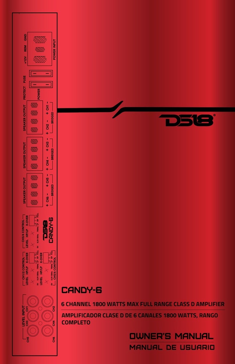
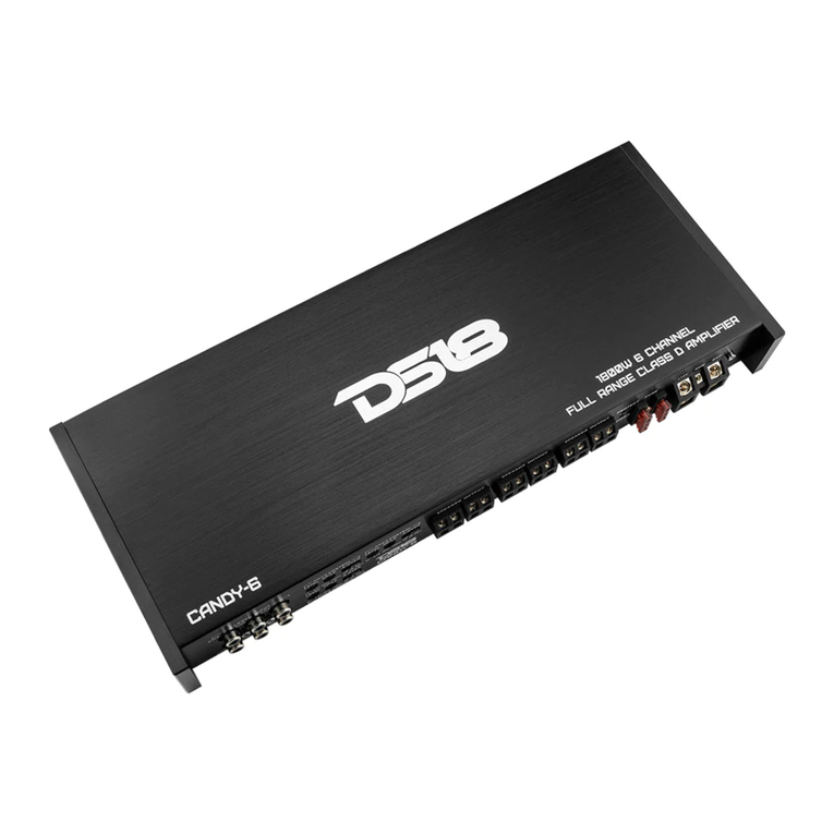
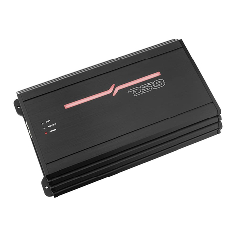
DS18 Candy-6 User manual

1
IMPORTANT IMPORTANTE!
owner’s manual
MANUAL DE USUARIO
Congratulations on purchasing this DS18
CANDY-6 Class D Full-Range Amplifier.
The amplifier has been designed using
the latest electronic technology available,
allowing you to produce high quality
stereo playback in mobile applications.
This system provides you with low
harmonic distortion, a considerable
amount of reserve voltage and high
temperature stability.
Felicitaciones por la compra de este
Amplificador Digital DS18 CANDY-6
de rango completo. El amplificador ha
sido diseñado utilizando última
tecnología electrónica disponible, lo que
permite producir una reproducción
estéreo de alta calidad en aplicaciones
móviles. Este sistema te proporciona una
baja distorsión armónica, una capacidad
considerable de reserva de voltaje y
estabilidad en las altas temperaturas.
- Dado que el amplificador es sensible al ruido
eléctrico, ruido del motor y a la interferencia
proveniente de sí mismo, esto puede afectar el
radio de recepción. Para evitar este problema,
intente instalarlo al menos a 3 pies de distancia
desde el receptor. Las posibles ubicaciones
pueden ser debajo del asiento, en el maletero o
en el área de la escotilla.
- Recuerde que se trata de una unidad de alta
potencia que genera mucha energía y calor. Por
lo tanto, asegúrese de instalar la unidad en un
lugar con suficiente flujo de aire, un mínimo de
polvo y sin humedad. Deje suficiente espacio
alrededor del aletas de enfriamiento para permitir
un flujo de aire y enfriamiento razonables. Es
importante asegurarse de que las aletas de
enfriamiento del disipador de calor no están
contra un panel o una superficie que impida la
circulación del aire.
- Nunca instale el amplificador en un lugar
expuesto a la luz solar directa o expuesto a la
humedad. Asegúrese de instalar el amplificador
en una superficie sólida y resistente que no cederá
bajo el estrés de una frenada repentina o un
accidente.
- Since the amplifier is sensitive to electrical
and motor noise and interference from the
amplifier may affect your radio reception, try
to mount it at least 3 feet away from the
receiver. Good locations include under a
seat, in the trunk or hatch area.
- Please remember this is a high power unit
which generates high electrical energy and
heat. Therefore be sure to install the unit in a
place with sufficient airflow, a minimum of
dust and no moisture. Allow enough space
around the cooling fins to permit reasonable
airflow and cooling. It is important to ensure
that the cooling fins of the heat sink are not
agains a panel or a surface preventing air
circulation.
- Never mount the amplifier in a location
that is subjet to direct sunlight or exposed to
moisture. Be sure to mount the amplifier to a
strong, solid surface which will not give way
under the stress of a sudden stop or
accident.
2
candy-6
- Cuando instale el amplificador en una pared
lateral, intente colocarlo de modo que las
ranuras las aletas de enfriamiento estén en
forma vertical. El amplificador no debe
instalarse con las aletas de enfriamiento hacia
abajo porque el calor irradiará hacia arriba en
dirección al amplificador. Deje suficiente espacio
a ambos lados del amplificador para hacer las
conexiones de cables y ajuste los controles. Si
tiene una caja de subwoofer en su vehículo,
puede instalar el amplificador en el exterior de la
caja.
- When mounting the amplifier on a side
wall, try to position it so that the slots in the
cooling fins are vertical. Amplifier should not
be mounted on the bottom a rear deck with
the fins facing down because the heat will
radiate back up into the amplifier. Leave
yourself enough room on either side of the
amplifier to make all the wire connections
and adjust the controls. If you have a
subwoofer box in your vehicle, you can
mount the amplifier on the outside of the
box. PRECAUCIÓN: Si está montando el
asegurarse de que sus tornillos no
perforarán un freno o una línea de gas.
CAUTION: if you are mounting the
amplifier to the vehicle’s floor, check
beneath the car to be sure your screws
wont puncture a brake or gas line.
ADVERTENCIA: La exposición continua
a niveles de presión sonora superiores a
100 dB puede causar pérdida auditiva
permanente. El sistema de sonido
automático de alta potencia puede
producir niveles de presión sonora muy
por encima de 130dB, use el sentido
común y utilice con seguridad el equipo
por favor!
WARNING: Continuous exposure to
sound pressure levels over 100dB may
cause permanent hearing loss. High
power autosound system may produce
sound pressure levels well over 130dB,
use common sense and practice safe
sound please!

3
owner’s manual
MANUAL DE USUARIO
Battery
Chassis
Ground
FUSE
CAR STEREO HEAD UNIT
CH5
CH6 CH4
CH3
LEVEL INPUT
CH1/2 CONTROL CH3/4 CONTROL
BRIDGED
CH6 CH5 CH4 CH3 CH2 CH1
BRIDGED BRIDGED
SPEAKER OUTPUT SPEAKER OUTPUT SPEAKER OUTPUT PROTECT
FUSE
+12V REM
POWER INPUT
GND
POWER
CH5/6 CONTROL
LEVEL HP/LP X-OVER
5V 0.2V 50Hz 750Hz LP HP FULL
5V 0.2V 50Hz 750Hz LP HP FULL 5V 0.2V 50Hz 750Hz LP HP FULL
LEVEL HP/LP X-OVER
LEVEL HP/LP X-OVER
CH1
CH2
CONEXIÓN ELÉCTRICA
POWER CONNECTION
PUENTE
SALIDA DE ALTAVOZ PROTECCIÓN
FUSIBLE
Fusible
ENTRADA DE
PODER
ENCENDIDO
ENTRADA DE NIVEL
Bateria
Tierra
Chasis
Chassis
Ground
Tierra
Chasis
UNIDAD DE AUDIO
IMPORTANTE: Antes de realizar cualquier
conexión, desconecte la batería del
automóvil hasta que se complete la
instalación para evitar posibles daños al
sistema eléctrico.
IMPORTANT: Before making any
connections, disconnect the car’s battery
until the installation is completed to
avoid possible damage to electrical
system

4
candy-6
CH5
CH6 CH4
CH3
LEVEL INPUT
CH1/2 CONTROL CH3/4 CONTROL
SPEAKER OUTPUT
BRIDGED
CH6 CH5 CH4 CH3 CH2 CH1
BRIDGED BRIDGED
SPEAKER OUTPUT SPEAKER OUTPUT PROTECT FUSE +12V REM
POWER INPUT
GND
POWER
CH5/6 CONTROL
LEVEL HP/LP X-OVER
5V 0.2V 50Hz 750Hz LP HP FULL
5V 0.2V 50Hz 750Hz LP HP FULL 5V 0.2V 50Hz 750Hz LP HP FULL
LEVEL HP/LP X-OVER
LEVEL HP/LP X-OVER
CH1
CH2
LINE INPUT
The LINE INPUT RCA jacks
must be connected with the
RCA output jacks of the
headunit.
POWER ON LED
Lights up when the amplifier is energized
indicating the unit is on.
PROTECT LED
Lights indicating the amplifier has gone
into a protection mode.
FUSE
Protects both this
amplifier and the
automobile electrical
system from short circuit
conditions.
INPUT LEVEL
Accepts line level (RCA) inputs
from 0.2v to 5V.
CROSSOVER SWITCH
Routes output of the full
range (FULL) , or a low pass
(LPF), or the output of the
high pass (HPF) filter to the
internal power amplifier.
LOW PASS
Variable Low Pass Filter from
50Hz to 750Hz.
HIGH PASS
Variable High Pass Filter
from 50Hz to 750Hz.
SPEAKER OUTPUT TERMINALS POWER SUPPLY TERMINALS
FEATURES

CH5
CH6 CH4
CH3
LEVEL INPUT
CH1/2 CONTROL CH3/4 CONTROL
SPEAKER OUTPUT
BRIDGED
CH6 CH5 CH4 CH3 CH2 CH1
BRIDGED BRIDGED
SPEAKER OUTPUT SPEAKER OUTPUT PROTECT FUSE +12V REM
POWER INPUT
GND
POWER
CH5/6 CONTROL
LEVEL HP/LP X-OVER
5V 0.2V 50Hz 750Hz LP HP FULL
5V 0.2V 50Hz 750Hz LP HP FULL 5V 0.2V 50Hz 750Hz LP HP FULL
LEVEL HP/LP X-OVER
LEVEL HP/LP X-OVER
CH1
CH2
ENTRADA DE LÍNEA
Las entradas LINE INPUT RCA
debe estar conectadas con el
RCA de la unidad principal.
LED DE ENCENDIDO
Se enciende cuando el amp está energizado
indicando que la unidad está encendida.
PROTECTOR LED
Luces que indican que el amplificador se
ha ido en modo de protección.
FUSIBLE
Protege tanto el
amplificador como el
sistema eléctrico del
automóvil de
cortocircuitos.
NIVEL DE ENTRADA
Acepta entradas de nivel de
línea (RCA) de 0.2v a 5V.
INTERRUPTOR X-OVER
Rutas de salida del rango completo,
o un filtro paso bajo (LPF), o la
salida del filtro de paso alto
(HPF) al amplificador de
potencia interno.
PASO BAJO
Filtrode paso bajo variable de
50Hz a 750Hz.
PASO ALTO
Filtrode paso alto variable
de 50Hz a 750Hz.
TERMi. DE SALIDA DE ALTAVOCES TERMIN. DE ALIMENTACIÓN
CARACTERISTICAS
5
owner’s manual
MANUAL DE USUARIO

6
candy-6
INPUT CONNECTIONS
level inputs. Low level signal is carried
through RCA cables. It is preferred to use
unit is equipped with the low level outputs.
SPEAKER OUTPUT CONNECTIONS
You do not need to make any adjustment
before you connect the speaker output.
- Connect subwoofer wire to corresponding
- Be sure to have the positive wire from the
speaker to the positive speaker terminal of
the speaker must connect with the speaker
these connections will result in the speaker
cones moving out of phase which causes
bass cancellation.
LEVEL CONTROLS
to Min initially.
Once the initial power sequence has been
performed, set the CD/RADIO volume
control to roughly 80% of full. Insert a CD
or tune to a radio station and slowly turn
for a clean sound.
APPLICATIONS
CONEXIONES DE ENTRADA
entradas de bajo nivel. La señal de nivel bajo es
utilizar entradas de bajo nivel en el
equipada con salidas de bajo nivel.
CONEXIONES DE SALIDA DE ALTAVOCES
No es necesario realizar ningún ajuste para la
conexión de entrada del
altavoz.
- Conecte el cable del subwoofer a los
terminales de salida de altavoz
- Asegúrese de tener el cable positivo del
altavoz conectado al terminal positivo del
deben conectarse con el terminal negativo del
conexiones provocará que los conos de los
altavoces se muevan fuera de fase, lo que
causaría cancelación en los bajos.
CONTROLES DE NIVEL
Min inicialmente.
Una vez realizada la secuencia de encendido
aproximadamente el 80% del total. Inserte un
CD o sintonice una estación de radio y
hasta que escuche algo de distorsión, y luego
apáguelo para obtener un sonido limpio.
APLICACIONES

Car Stereo System
CH1
CH5
CH6 CH4
CH3
LEVEL INPUT
CH1/2 CONTROL
X-OVER
LP HP FULL
X-OVER
LP HP FULL
LP HP FULL
X-OVER
CH3/4 CONTROL
SPEAKER OUTPUT
BRIDGED
CH6 CH5 CH4 CH3 CH2 CH1
BRIDGED BRIDGED
2-8Ohms speaker 2-8Ohms speaker
CH5 CH3 CH1
2-8Ohms speaker 2-8Ohms speaker 2-8Ohms speaker
CH6 CH4 CH2
SPEAKER OUTPUT SPEAKER OUTPUT PROTECT FUSE +12V REM
POWER INPUT
GND
POWER
CH5/6 CONTROL
LEVEL HP/LP X-OVER
5V 0.2V 50Hz 750Hz LP HP FULL
5V 0.2V 50Hz 750Hz LP HP FULL 5V 0.2V 50Hz 750Hz LP HP FULL
LEVEL HP/LP X-OVER
LEVEL HP/LP X-OVER
CH1
CH2
CH2
CH3
CH4
CH5
CH6
7
owner’s manual
MANUAL DE USUARIO
APLICACIONES- MODO DE 6 CANALES
APPLICATIONS - 6 CHANNEL MODE
UNIDAD PRINCIPAL
SALIDA DE SPEAKER
PUENTE
PROTECCIÓN
ENTRADA DE PODER
ENCENDIDO
ENTRADA DE NIVEL
FUSIBLE
2-8Ohms speaker

Car Stereo System
CH1
CH5
CH6 CH4
CH3
LEVEL INPUT
CH1/2 CONTROL
X-OVER
LP HP FULL
X-OVER
LP HP FULL
LP HP FULL
X-OVER
CH3/4 CONTROL
SPEAKER OUTPUT
BRIDGED
CH6 CH5 CH4 CH3 CH2 CH1
BRIDGED BRIDGED
2-8Ohms speaker 2-8Ohms speaker
4-8Ohms speaker 2-8Ohms speaker
CH3 CH1
Subwoofers
CH4 CH2
SPEAKER OUTPUT SPEAKER OUTPUT PROTECT FUSE +12V REM
POWER INPUT
GND
POWER
CH5/6 CONTROL
LEVEL HP/LP X-OVER
5V 0.2V 50Hz 750Hz LP HP FULL
5V 0.2V 50Hz 750Hz LP HP FULL 5V 0.2V 50Hz 750Hz LP HP FULL
LEVEL HP/LP X-OVER
LEVEL HP/LP X-OVER
CH1
CH2
CH2
CH3
CH4
CH5
CH6
APLICACIONES- MODO DE 5 CANALES
8
candy-6
APPLICATIONS - 5 CHANNEL MODE
DINMittelschriftStd*
UNIDAD PRINCIPAL
SALIDA DE SPEAKER
PUENTE
PROTECCIÓN
ENTRADA DE PODER
ENCENDIDO
ENTRADA DE NIVEL
FUSIBLE
2-8Ohms speaker

owner’s manual
MANUAL DE USUARIO
Car Stereo System
CH1
CH5
CH6 CH4
CH3
LEVEL INPUT
CH1/2 CONTROL
X-OVER
LP HP FULL
X-OVER
LP HP FULL
LP HP FULL
X-OVER
CH3/4 CONTROL
SPEAKER OUTPUT
BRIDGED
CH6 CH5 CH4 CH3 CH2 CH1
BRIDGED BRIDGED
2-8Ohms speaker
CH1
Subwoofers
4-8Ohms speaker 2-8Ohms speaker
CH2
SPEAKER OUTPUT SPEAKER OUTPUT PROTECT FUSE +12V REM
POWER INPUT
GND
POWER
CH5/6 CONTROL
LEVEL HP/LP X-OVER
5V 0.2V 50Hz 750Hz LP HP FULL
5V 0.2V 50Hz 750Hz LP HP FULL 5V 0.2V 50Hz 750Hz LP HP FULL
LEVEL HP/LP X-OVER
LEVEL HP/LP X-OVER
CH1
CH2
CH2
CH3
CH4
CH5
CH6
APPLICATIONS - 4 CHANNEL MODE APLICACIONES- MODO DE 4 CANALES
9
UNIDAD PRINCIPAL
SALIDA DE SPEAKER
PUENTE
PROTECCIÓN
ENTRADA DE PODER
ENCENDIDO
ENTRADA DE NIVEL
FUSIBLE
Subwoofers
4-8Ohms speaker

10
SPECIFICATIONS
CANDY-6MODEL /
class / class-d /
6
80W x6ch
125W x6ch
250W x3ch
channels /
rms power @ 4 ohm /
rms power @ 2 ohm /
1800W
10Hz-60kHz
50HZ-750Hz
45Hz
<0.01%
LPF/HPF/FULL
9-16v
2X40A
4ga
>80
0-12
0.2-5V
TOTAL WATTS (PEAK) /
rms power @ 4 ohm bridge /
frequency response /
THD % /
SELECTABLE X-OVER /
signal/noise ratio /
X-OVER FILTER RANGE /
BASS BOOST FREQUENCY /
POWER/PROTECTION
LED INDICATOR /
THERMAL PROTECTION /
bass boost RANGE /
voltage input protection /
fuse rating /
power input size /
>158OF
yes / SI
yes / SI
dimensions LxDxH (inches) / 14.4 x 5.7 x 1.69” /
low level input range /
over-load protection /
short circuit output protection /
candy-6
ESPECIFICACIONES
MODELO
CLASE DIGITAL
CANALES
PODER CONTINUO @ 4 ohm
PODER CONTINUO @ 2 ohm
VATIOS TOTALES (PICO)
PODER CONTINUO @ 4 ohm PUENTE
RESPUESTA DE FRECUENCIA
DISTORCION ARMONICA TOTAL (THD)%
CROSSOVER SELECCIONABLE
PROPORCIóN DE RUIDO/sEÑAL
RANGO DE FILTRO DE X-OVER
FREQ DEL REFUERZO DE GRAVES
INDICADOR LED
PROTECCIÓN TERMICA
RANGO DE REFUERZO DE GRAVES
PROTECIÓN DE VOLTAGE DE ENTRADA
CAPACIDAD DE FUSIBLES
CALIBRE DE CABLE DE ENTRADA
DIMENCIONES LxAxA (CENTIMETROS) 36.57x 14.47x 4.29
RANGO DE ENTRADA DE BAJO NIVEL
PROTECCIÓN DE SOBRECARGA
PROTECCIóN DE CORTO CIRCUITO

V1
Other manuals for Candy-6
4
Table of contents
Other DS18 Amplifier manuals