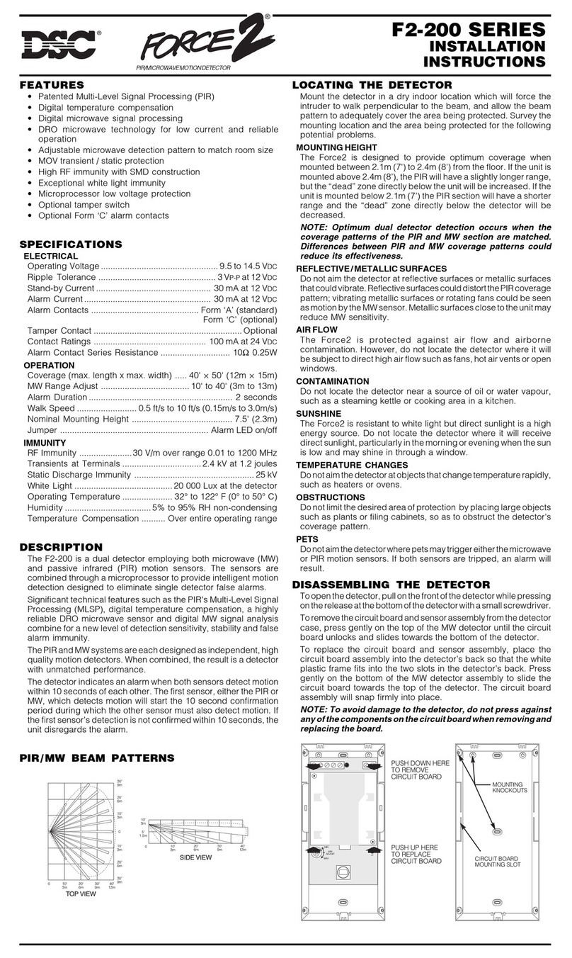
DSC CFP-500 User manual

CFP-500
Installation
Manual
WARNING: This manual contains information on limitations regarding
product use and function and information on the limitations as to liability
of the manufacturer. The entire manual should be carefully read.
CFP-500
Dual Line Dialer
· ·
Version 1.0
firealarmresources.com

Table of Contents
Section 1: Introduction ................................................. 1
1.1 General Features of the CFP-500 ............................. 1
1.2 Codes, Standards and Installation Requirements ........ 1
1.3 Technical Support and General Information ............... 2
Section 2: Installing and Wiring the CFP-500 ................. 3
2.1 Unpacking the CFP-500.......................................... 3
2.2 Wiring the CFP-500................................................ 3
Section 3: CFP-500 Operation ...................................... 5
3.1 LED Indicators ....................................................... 5
3.2 Communication with the Fire Alarm Control Panel...... 5
3.3 Phone Line Communication ..................................... 5
Section 4: Programming the CFP-500 ........................... 6
4.1 How to program using the CFP-550 Handheld
Programmer ........................................................... 6
4.2 DLS Programming................................................. 12
4.3 Panel Programming Section Descriptions................. 12
Section 5: Programming Worksheets ........................... 16
5.1 Dialer Programming Worksheets............................. 16
5.2 Panel Programming Worksheets ............................. 21
Section 6: Warranty and Warning Information .............. 22
6.1 Warning ............................................................. 22
6.2 Limited Warranty.................................................. 24
Appendix A: Table of Reporting Codes ........................ 25
Appendix B: Table of Compatible Receivers ................. 27
firealarmresources.com

1
Section 1: Introduction
The CFP-500 is a dual line dialer that will communicate all alarms, supervisory and trouble conditions to a Central Station using
Contact ID, SIA or 10/20 bps communication formats. The CFP-500 will support the CFP-102 or CFP-105 Fire Panel. The
CFP-550 Handheld Programmer must be used to program the CFP-500 Dialer.
1.1 General Features
of the CFP-500
• Supports all zone alarm, supervisory, and trouble conditions
• Supports all panel troubles
• Programmable through CFP-550 Handheld Programmer
• Supports 10/20 bps, SIA, Contact ID, and Pager Formats
• Three telephone numbers
• Fully programmable test transmission
• Automatic reporting codes for SIA and Contact ID formats
• 128-event buffer with date and time stamp
• Communicator call directions by group
• Swinger shutdown options available for all events
• Module current rating: 40mA standby / 65mA when dialing
• Module voltage rating: 19 VDC to 27.5 VDC
1.2 Codes, Standards
and Installation
Requirements
1.2.1 Relevant Codes and Standards
The CFP-500 Dual-Line Digital Dialer is designed to meet the DACT requirements of NFPA 72,
1996 edition UL 864, Control Units for fire Protective Systems, 1996 edition and in Canada,
CAN/ULC-S527, Standard for Control Units for Fire Alarm Systems, 1999 edition.
1.2.2 General Installation Requirements
Manufacturer’s Documents
When installing the CFP-500, refer to this manual and the manual for the control panel into
which this module is being installed. This dialer requires programming. Programming is done
using the CFP-550 programmer. Refer to the CFP-550 operating instructions for details on pro-
gramming using the CFP-550.
Field Wiring
Field wiring recommendations in these documents are intended as guidelines. All field wiring
must be installed in accordance with NFPA 70 National Electrical Code and in Canada with
the most current National Electrical Code and with all relevant local codes and standards and
the Authority Having Jurisdiction.
firealarmresources.com

2
1.3 Technical
Support and
General
Information
For technical support from DSC: Call toll free 1-800-387-3630 (Canada & US)
For general product information visit our web site: www.dsc.com
1.3.1 System Verification
The complete fire alarm system must be verified for proper installation and operation when:
• the initial installation is ready for inspection by the Local Authority Having Jurisdiction;
• any system component is added, changed or deleted;
• any programming changes are made;
• system wiring has been altered or repaired;
• system failure due to external influences such as lightning, water damage or extended
power outages has occurred.
1.3.2 Standby Power
The CFP-102/CFP-105 Fire Panel provides standby battery support for lead-acid rechargeable
batteries. The required capacity of the standby batteries must be calculated using the charts
and tables within the CFP-102/CFP-105 Installation Manual for the period as required by
national or local codes and standards. Even though the calculation table within the CFP-102/
CFP-105 Installation Manual includes a safety margin, lead-acid batteries commonly used for
standby can have variable capacity as a result of age and ambient conditions. Periodic
inspection for damage and the batteries’ ability to support the attached equipment is highly
recommended.
firealarmresources.com

3
Section 2: Installing and Wiring the
CFP-500
2.1 Unpacking the
CFP-500
The basic CFP-500 package includes the following components:
❑Dialer
❑4-pin polarized locking cable assembly
❑Four #4 self-locking nuts
❑Installation manual
❑Four nylon spacers
2.2 Wiring the
CFP-500
NOTE: Ensure that standby calculations are done before installing the dialer. See the
CFP-102/CFP-105 Fire Panel Installation Manual for all power information and calculation
charts. The current rating for the CFP-500 is:
• 40 mA standby current
• 65 mA alarm current (when dialing)
2.2.1 Mount the CFP-500
The CFP-500 is located inside the main panel cabinet according to the following diagram:
firealarmresources.com

4
2.2.2 Connect the CFP-500
The CFP-500 requires connection of the Secur-bus from the dialer to the main panel using the
provided 4-pin polarized locking cable assembly. Up to two telephone lines are connected to
the Tip/Ring/T1/R1 terminals.
Connect the dialer according to the following diagram:
firealarmresources.com

5
Section 3: CFP-500 Operation
3.1 LED Indicators The dialer’s operating status is visible from its five LED indicators. These indicators are located
on the dialer. Each indicator is described in the following table:
3.2 Communication
with the Fire
Alarm Control
Panel
When connected to the FACP properly, the Watchdog LED will flash at a rate of ½ second on/
off when power is applied to the FACP. The dedicated dialer will transmit all events that occur
on the FACP if programmed to do so. Any troubles that occur on the dedicated dialer will be
shown on the appropriate LED and communicated (if enabled) as well as causing a common
trouble condition on the FACP. If the FACP should lose communication with the dialer a com-
mon trouble condition will also be generated.
3.3 Phone Line
Communication
The dedicated dialer is equipped with two phone line connections. When an event occurs that
initiates communications, the first attempt at dialing will be on telephone line #1. If the
attempt fails, the dialer will then select telephone line #2 for the next attempt at dialing. This
will continue until the maximum number of dialing attempts is reached. Please note that on
the first attempt to telephone line #1, if a telephone line trouble exists on line #1 and not line
#2, then the first attempt will start on line #2.
# Indicator LED Color Activates when...
1 Secur-bus Fault Yellow the Secur-bus connection to the main panel has failed
2 TLM2 Trouble Yellow there is a trouble on telephone line #2
3 TLM1 Trouble Yellow there is a trouble on telephone line #1
4 FTC Trouble Yellow the dialer is unable to communicate
5 Watchdog Green the dialer is functioning normally; LED flashes ½ second
on, ½ second off
firealarmresources.com

6
Section 4: Programming the CFP-500
4.1 How to program
using the
CFP-550
Handheld
Programmer
4.1.1 Connect the CFP-550 to the Dialer
The CFP-550 connects to the dialer via the RJ-11 jack mounted on the dialer. An RJ-11 con-
nector cable is provided with the handheld programmer. Refer to the wiring diagram in “Con-
nect the CFP-500” on page 4 for the location of the RJ-11 jack.
Once the programmer is connected, it will power up and remain idle until programming is initiated.
4.1.2 Programming using the CFP-550
To program, follow these steps:
1. Press [*].
The programmer display will read “Enter Module Address.”
The dialer’s module address = 11.
The control panel address = 02
2. Enter [11] (for example).
The programmer display will read “Enter Installer Code” The default code = 2600.
3. Enter the installer’s code.
The display will read “Enter Section Number”
4. Enter a valid 3-digit programming section number to program that section.
5. Enter the programming data required by the selected programming section. Use the arrow
keys (< >) to view the programming data in the selected programming section.
To return to “Enter Module Address”, press [#] from the “Enter Section Number” display.
4.1.3 Entering Hexadecimal Digits
On occasion, hexadecimal (HEX) digits may be required. To program a HEX digit (A-F), press
the [*] key at any HEX data entry section. The panel will enter the HEX programming mode.
The following indicates which number should be pressed to enter the corresponding HEX digit:
1 = A 2 = B 3 = C 4 = D 5 = E 6 = F
If another HEX digit is required press the [*] key followed by the corresponding number entry.
After every HEX entry, the programmer will return to standard number entry.
4.1.4 Dialer Programming Section Descriptions
Telephone Numbers, Section [001]-[003] and [411] for DLS Phone Number
Telephone numbers can be up to 32 digits, allowing the addition of special digits, if required.
To program the telephone number, enter numbers 0 through 9 as required. Hexadecimal digits
(B-F) can also be used to perform the following functions:
HEX (B)-simulates the [*] key on a touch tone telephone
HEX (C)-simulates the [#] key on a touch tone telephone
HEX (D)-forces the panel to search for dial tone
HEX (E)-forces the panel to pause for 2 seconds
HEX (F)-end of telephone number marker
Three telephone numbers can be programmed. When programming, press the [#] key once
the telephone number is entered to exit the programming section.
Account Codes, Sections [011]-[012]
The account code identifies the panel to the central station when a communication is sent. Use
up to four digits for account codes.
When communicating events via the first or third telephone number, the first account code is
used. The second telephone number uses the second account code.
firealarmresources.com

PROGRAMMING THE CFP-500
7
Dialing Options, Section [051]-[052]
The options in programming sections [051]-[052] are explained below. Where applicable,
other sections of the manual will be referenced for more information regarding the feature.
The default setting for each option (ON or OFF) is indicated with an *.
• [051] First Communicator Options
• [1] - [3] For future use
• [4] Third Telephone Number Enable / Disable
ON = The third telephone number will be used for alternate dialing or backup
(see following option 5).
*OFF = The third telephone number will not be used.
• [5] Third Telephone Number Options
ON = Alternate Dialing Enabled. After each dialing attempt, the communicator
switches between the first and third telephone numbers until the maxi-
mum number of dialing attempts have been made to each number.
*OFF = Third Number Backup. If all attempts to communicate to the first tele-
phone number fail, the dialer will use the third telephone number. If all
attempts to communicate to the third number fail, a failure to communi-
cate trouble will be generated.
• [6] Dialing Format Options
ON = The dialer will use pulse (rotary) dialing.
*OFF = The dialer will use DTMF dialing (see following option 7).
• [7] DTMF Crossover Options
ON = If DTMF dialing is enabled in previous option 6, the dialer will use DTMF
dialing for the first four attempts. If unsuccessful, the dialer will switch to
pulse (rotary) dialing for the remaining attempts.
*OFF = If DTMF dialing is enabled in previous option 6, the dialer use DTMF
dialing for all dialing attempts.
• [8] Event Buffer Swinger Options
*ON = Once an event reaches its swinger shutdown limit, it will no longer log to
the event buffer until the swinger shutdown is reset. This avoids filling
the Event Buffer with repeated events. See Section 4.2.10 “Swinger
Shutdown” for more information.
OFF = Event buffer logs events past swinger shutdown.
•[052] Second Communicator Options
• [1] SIA Reporting Code Options
See “Communicator Format Options, Section [021]” on page 9 for more information.
ON = SIA sends programmed reporting codes
*OFF = SIA sends automatic reporting codes
• [2] SIA Maximum Events Per Round Options
See “Communicator Format Options, Section [021]” on page 9 for more information
ON = SIA sends maximum of 20 events per round
*OFF = SIA sends maximum of 8 events per round
• [3] Contact I.D. Options
See “Communicator Format Options, Section [021]” on page 9 for more information
ON = Contact ID sends programmed reporting codes
*OFF = Contact ID sends automatic reporting codes
• [4] Test Transmission Dialing Options
See “Test Transmissions, Sections [041]-[042]” on page 11 for more information
*ON = Test transmission alternates telephone lines.
OFF = Test transmission uses first available line.
• [5] – [6] For Future Use
• [7] DLS Callback
ON = DLS Callback Enabled. If the remote computer connects with the dialer
and this option is enabled, the dialer will disconnect from the computer
and call the DLS phone number programmed. Once the DLS connection
is re-establish communications will begin.
firealarmresources.com

8
*OFF = DLS Callback Disabled. When the remote computer connects to the
dialer communications will begin.
• [8] DLS Double Call
ON = DLS Double Call Enabled. If there is more than 7 seconds delay and less
than the programmed DLS Double Call window timer between the first/
second and the second/third ring, the dialer will answer the incoming
call.
*OFF = DLS Double Call Disabled. The dialer will require the programmed num-
ber of rings before answering an incoming call.
•[053] International Communicator Options Code
• [1] Force Dial Options
ON = Force Dialing Enabled. If the first attempt by the panel to call the moni-
toring station fails, on every subsequent attempt the panel will dial
regardless of the presence of dial tone.
NOTE: The panel will go off-hook, search for dial tone for 5 seconds, hang-up
for 20 seconds, of off-hook, search for dial tone for 5 seconds. then dial
(assuming no presence of dial tone).
*OFF = Force Dialing Disabled. The panel will not dial the programmed tele-
phone number if dial tone is not present.
• [2] Busy Tone Options
ON = Busy Tone Detection Enabled. If these tones are detected, the communi-
cator will disengage the phone line and try to place the call again follow-
ing the “Delay Between Dialing Attempts”.
*OFF = Busy Tone Detection Disabled, The communicator will use the standard
dialing procedure for every attempt.
• [3] Pulse Dial Options
ON = Pulse Dialing Make/Break Ratio is 33/67.
*OFF = Pulse Dialing Make/Break Ratio is 40/60.
• [4] Handshake Options
ON = 1600 Hz Handshake. The communicator responds to a 1600 Hz hand-
shake for bps formats.
*OFF = Standard Handshake. The communicator responds to the handshake
designated by the format selected (1400 or 2300 Hz).
• [5] I.D. Tone Options
ON = I.D. Tone Enabled. After the telephone number is dialed, the panel will
emit a tone (as specified by Option 6) for 500 ms every 2 seconds to
indicate that it is a digital equipment call, not voice.
*OFF = I.D. Tone Disabled.
• [6] I.D. Tone Frequency
ON = 2100 Hz I.D. Tone Enabled. This option requires option 5 to be enabled.
*OFF = 1300 Hz I.D. Tone Enabled. This option requires option 5 to be enabled.
• [7] - [8] For future use
Communicator Call Directions, Sections [031]-[035]
Communicator call directions must be programmed to indicate which telephone numbers the
dialer will use to communicate events. The dialer can send reporting codes to the first and/or
second telephone number(s). By default, all events are sent to the first telephone number.
Communicator call directions are programmed separately for each of the following types of
reporting codes:
• zone alarms and restorals [031]
• supervisory zone alarms and restorals [032]
• zone troubles and restorals [033]
• maintenance troubles and restorals [034]
• test transmissions [035]
firealarmresources.com

PROGRAMMING THE CFP-500
9
Communicator Format Options, Section [021]
A 2-digit entry is required for each telephone number. Only one communicator format may be
programmed for each telephone number. The following communicator formats are available for
the dialer:
1. 10 or 20 bps Pulse
2. Contact ID
3. SIA
4. Pager
Each format is explained below.
Pulse Formats
Depending on the pulse format selected the panel will communicate using the following:
• 10 bps, 1400 Hz handshake
• 10 bps, 2300 Hz handshake
• 20 bps, 1400 Hz handshake
• 20 bps, 2300 Hz handshake
Obey the following when using the Pulse format:
• The digit ‘0’ will send no pulses and is used as a filler.
• Account numbers must be four digits. . If a 3-digit code is required, program the fourth
digit as ‘0’.
• The digit ‘0’ is not used in this format—substitute with HEX digit ‘A’.
• All reporting codes must be two digits. If a single-digit code is required, program the sec-
ond digit as ‘0’.
• To prevent the panel from reporting an event, program the reporting code as [00] or [FF].
Contact ID
Contact ID is a specialized format that will communicate more information quickly using tones
rather than pulses.
When using Contact ID, obey the following:
• Account numbers must be four digits.
• The digit ‘0’ is not used in this format—substitute with HEX digit ‘A’.
• All reporting codes must be two digits.
• To prevent the panel from reporting an event, program the reporting code as [00] or [FF].
Contact ID Communicator Options [052] #3
If Contact ID Uses Automatic Reporting Codes is selected, the dialer will automatically
generate a reporting code for each event. These identifiers are listed in Appendix A. If the
reporting code [00] is programmed, no transmission will be sent.
If the Contact ID uses Programmed Reporting Codes option is selected, the dialer will
only communicate events for which valid reporting codes are programmed.
Consult the following table for clarification of this feature:
Reporting Code Entry Programmed Reporting Codes Automatic Reporting Codes
00 No Transmission No Transmission
FF No Transmission Automatic reporting code sent
01-FE 01-FE sent Automatic reporting code sent
firealarmresources.com

10
SIA
The SIA format communicates information quickly using frequency shift keying (FSK) rather
than pulses. The 2-digit reporting code is used to identify the zone.
SIA Communicator Options [052] #1-2
If the SIA Sends Automatic Reporting Codes option is selected, the dialer will automati-
cally generate a reporting code for each event. These identifiers are listed in Appendix A. If
the reporting code [00] is programmed, no transmission will be sent.
If the SIA Sends Programmed Reporting Codes option is selected, the dialer will only
communicate events for which valid reporting codes are programmed.
Consult the following table for clarification of this feature:
If the SIA Sends Maximum of 8 Events per Round option is enabled, the dialer will limit
its communication round to eight events. This ensures compatibility with all receivers sup-
porting the SIA format. If the SIA Sends Maximum of 20 Events per Round, the dialer will
send up to 20 events in one round. NOTE: Not all receivers will accept this many events.
Be sure to check the receiver for compatibility.
Pager Format
Events will be communicated to a pager when using this format.
When programming a pager telephone number, extra digits must be used in order for the fea-
ture to function properly. Program two hexadecimal digits ‘E’ at the end of the telephone num-
ber (a 4-second pause). For more information on programming telephone numbers, see
Section 4.2.1 “Telephone Numbers”.
The panel will attempt to call the pager one time. After dialing the digits in the telephone num-
ber the panel will send the account number and reporting code followed by the [#] key (Hex
[C]).
There is no ringback when using Pager format. The panel has no way of confirming if the pager
was called successfully; a failure to communicate trouble will only be generated once the maxi-
mum number of attempts has been reached.
NOTE: Do not use hexadecimal digit C in a reporting code when using Pager Format. In most
cases, the digit C will be interpreted as a [#], which will terminate the page before it has fin-
ished.
Communication Variables, Sections [081]-[084]
TLM Trouble Delay [081]
This value represents the number of valid checks (10 second interval) required before a tele-
phone line trouble is generated. Valid entries are 000-255, providing trouble annunciation and
transmission delays of 10 to 2550 seconds (42.5 minutes).
AC Trouble Delay [082]
This value represents the time (in hours) the communicator waits upon receiving an AC trouble
condition from a fire control panel before transmitting it. Valid entries are 000-255 where 000
is disabled.
Maximum Dialing Attempts To Each Telephone Number [083]
This value represents the number of attempts that will be made to each telephone number
when communicating. The default value is 007 attempts. Valid entries are 001-015.
Post Dial Wait for Handshake [084]
This value represents the amount of time the communicator will wait for a valid initial hand-
shake from the receiver after dialing the programmed telephone number. The default value is
040 seconds.
Reporting Code Entry Programmed Reporting Codes Automatic Reporting Codes
00 No Transmission No Transmission
FF No Transmission Automatic reporting code sent
01-FE 01-FE sent Automatic reporting code sent
firealarmresources.com

PROGRAMMING THE CFP-500
11
Reporting Codes, Sections [201]-[270]
Unless you are using Automatic Contact ID or Automatic SIA formats, reporting codes must be
programmed in order for the panel to report events to the central station.
Reporting codes are two digits and can use hexadecimal digits A through F. To disable a report-
ing code, program it as “FF” (default setting) or “00”. For a complete description of reporting
codes which can be programmed and lists of automatic Contact ID and SIA format codes,
please see Appendix A: “Reporting Codes”.
Event Buffer, Section [902]
The system’s event buffer can be viewed in the programming mode. Up to 128 events are
stored in the buffer memory. The event number will be displayed along with the time and date
when the event occurred. Use the [*] key to toggle between the event description and the time
and date stamp. Use the arrow keys (< >) to scroll through the events in memory.
Swinger Shutdown, Section [061]
Swinger shutdown levels determine the number of events the dialer will attempt to communi-
cate before the zone is shut down. A 3-digit entry is required, from 000-255. If 000 is pro-
grammed, the feature will be disabled and all events will be transmitted. A separate swinger
shutdown value is programmed for the following events:
• fire zone alarms/restorals
• supervisory zone alarms/restorals
• zone trouble alarms/restorals
• maintenance troubles/restorals
Test Transmissions, Sections [041]-[042]
The dialer can be programmed to send test transmissions to the monitoring station to verify
proper communications.
The Transmission Time of Day determines when the test transmission will occur. The entry is
four digits (HH:MM). To disable the feature, program the time as [9999].
The Test Transmission Cycle will determine the period between test transmissions
NOTE: In order for this feature to function, the panel time and date must be programmed.
See Section 4.2.10 “Time & Date” for more information.
Test Transmission Communicator Options [052] #4
If the Test Transmission Alternates Telephone Lines option is selected, the dialer will alter-
nate between using Telephone Lines 1 and 2 for transmissions, regardless of telephone
line troubles.
If the Test Transmission Uses First Available Line option is selected, the dialer will use
Telephone Line 1 for transmissions. If a trouble exists on Telephone Line 1, the dialer will
switch to Line 2.
Zone Definitions, Section [101]
When using the SIA or Contact ID formats, the control panel zones must be defined in the
dialer module. Once the zones are defined, communications of events will include the correct
zone type. Each zone type is a 2-digit entry.
The available zone types are as follows:
[01] Fire [06] Panic [10] Freeze
[02] Fire Supervisory [07] Emergency [11] Heat
[03] Sprinkler [08] Medical [12] Water
[04] Burglary [09] Gas [13] Untyped
[05] Holdup
firealarmresources.com

12
4.2 DLS
Programming
4.2.1 [401] Number of Rings to Answer On
This is the number of rings the dialer requires before answering an incoming call. Ring detect
supports Line One only. Programming 000 disables ring detect.
Valid entries are 000-255. Default is 012.
4.2.2 [402] DLS Double Call Window
This is the maximum amount of time the panel will wait between rings to answer an incoming
call with the double call feature. Programming 000 disables this timer.
Valid entries are 000-255 seconds. Default is 060.
4.2.3 [403] DLS Download Enable Timer
In order to program the system from a remote computer, this timer must be enabled with 001-
254 minutes. When programmed, downloading of the system will be allowed until the timer
expires. Uploading of the system information is always enabled.
Valid entries are 000-254. Default is 000.
4.2.4 [421] DLS Access Code
This is the access code required by the dialer in order to allow programming from the down-
loading computer.
The access code must be 4 hexadecimal digits in length.Default is 2600.
4.2.5 [422] DLS Panel ID Code
This is the identification code required by the downloading computer to identify the dialer
module being programmed.
The access code must be 4 hexadecimal digits in length. Default is 2600.
4.3 Panel
Programming
Section
Descriptions
With the addition of the dialer module, the following additional items must be programmed in
the control panel. To program these sections, use of the CFP-550 handheld programmer is
required. Follow the same procedure for programming as indicated in “Programming using the
CFP-550” on page 6. The control panel module address is [02].
NOTE: The installer code will not be required after entering the panel module address.
4.3.1 Zone Programming [001]
This section requires 2 (MR2602) or 5 (MR2605) two-digit entries. Valid entries and descrip-
tion of each entry is shown below.
00 Null Zone
The zone is not used. The zone is not supervised and alarms and troubles are ignored. The End
of Line Resistor is not required.
01 Instant
Both smoke detectors and contact devices cause an instant alarm.
02 Auto Verify
Smoke detectors on that zone will be verified before an alarm is initiated. If this type of alarm
occurs with an alarm present on the system, or the auto-verify timer is active, this zone will
become an instant alarm.
03 Waterflow
Classifies the zone as a waterflow zone. All alarms are instant unless the waterflow delay is
enabled. If the delay is enabled, then when a zone goes into alarm a fixed 60 second delay
starts. At the end of the delay any waterflow zones still in alarm will cause the panel to go into
alarm. The delay will not be restarted on any subsequent waterflow alarms.
firealarmresources.com

PROGRAMMING THE CFP-500
13
04 Supervisory
Classifies the zone as a fire supervisory. All alarms are instant and will turn on the buzzer
instead of the bell. Pressing the Trouble Silence Switch silences the supervisory buzzer. If a
Supervisory occurs while there is another zone alarm, the Signal Silence switch will silence
both the Alarm and Supervisory conditions. Silencing a Supervisory Alarm does not activate
the Signal Silenced trouble.
05 Four Wire Smoke (only) Auto Verify
Smoke detectors on that zone will be verified before an alarm is initiated. If this type of alarm
occurs with an alarm present on the system, or the auto-verify timer active, this zone will
become an instant alarm.
WARNING: Manual Pull Stations MUST NOT be used on this zone type.
4.3.2 Panel System Option Code One [011]
[1] NAC1 Output Options
ON = NAC1 is Temporal. NAC1 will sound the Temporal/ANSI Fire Pattern of
0.5 seconds ON, 0.5 seconds Off, 0.5 seconds On, 0.5 seconds Off, 0.5
seconds On, 1.5 seconds Off, repeat.
OFF = NAC1 is Steady. NAC1 will stay on steady for an alarm condition.
[2] NAC2 Output Options
ON = NAC2 is Temporal. NAC2 will sound the Temporal/ANSI Fire Pattern of
0.5 seconds ON, 0.5 seconds Off, 0.5 seconds On, 0.5 seconds Off, 0.5
seconds On, 1.5 seconds Off, repeat.
OFF = NAC2 is Steady. NAC2 will stay on steady for an alarm condition.
[3] NAC Silence Options
ON = Automatic Signal Silence is Enabled. If enabled, the timer starts on the
first fire alarm and is restarted on subsequent fire alarms from other
zones. When the timer reaches 30 minutes from the last fire alarm, the
NAC’s are restored to normal. If after the panel has been silenced, either
manually or automatically, another alarm occurs it will restart the timer
for a full timing period.
OFF = Automatic Signal Silence is Disabled. The NAC’s will continue to sound
until the Signal Silence key is pressed.
[4] NAC2 Strobe Options
ON = NAC2 is a Strobe. NAC2 is restored to normal following a successful Sys-
tem Reset.
OFF = NAC2 is a Standard Bell. NAC2 is restored to normal following a Signal
Silence.
[5] Signal Silence Inhibit Options
ON = Signal Silence Inhibit Timer is Enabled. While in force, this timer pre-
vents manual signal silencing for 60 seconds. The timer is started on the
first alarm only and is not restarted on subsequent alarms. If after man-
ual or automatic silencing (no reset) a subsequent alarm occurs, the
Silence Inhibit timer is not started. This timer is only started on the first
fire alarm after a successful panel reset.
OFF = Signal Silence Inhibit Timer is Disabled. The Signal Silence key will
silence the alarm.
firealarmresources.com

14
[6] Walk Test Audible Options
ON = Walk test is Audible. On a fire or supervisory alarm the NAC’s will pulse
once – ¼ sec. On a zone or system trouble, except ground fault, the
NAC’s will sound twice – ¼ ON, ¼ OFF, ¼ ON and OFF. For ground fault
the NAC’s will sound three times – ¼ ON, ¼ OFF, ¼ ON, ¼ OFF, ¼ ON
and OFF.
OFF = Walk test is Silent. The NAC’s will not sound during walk test.
[7] Waterflow Zone Delay Options
ON = Waterflow Zone Alarms are Delayed. The Waterflow delay is a fixed timer
- 60 seconds - and applies to all zones that are set as zone type “water-
flow”. The first waterflow zone to go into alarm will start the timer and it
is not restarted on subsequent waterflow alarms from another waterflow
zone. When the timer expires, any waterflow type zone still in alarm will
cause the panel to go into alarm. If during the waterflow delay period,
any other type of fire zone goes into alarm, the panel will immediately go
into alarm in response to that zone.
OFF = Waterflow Zone Alarms are not Delayed. Zone’s programmed as “water-
flow” will go into alarm instantly.
[8] Waterflow Zone Silence Options
ON = Waterflow Zones can be Silenced. Regardless of their state, the NAC’s
can be silenced. This applies to both manual and automatic signal
silence.
OFF = Waterflow Zones cannot be Silenced. Until physically restored, the
NAC’s can’t be silenced. This applies to both manual and automatic sig-
nal silence. However, If the zone enters the trouble state (open) following
the alarm (short) and alarm restore, the zone shall be silenceable.
4.3.3 Panel System Option Code Two [012]
[1] Auto Verify Fault Options
ON = Auto Verify Fault is Alarm. If a zone initiates an auto verify sequence and
returns from power down in the open (trouble) state, the system will
treat this as an alarm condition and assume that the circuit has been
forced open by fire.
OFF = Auto Verify Fault is Trouble. If a zone initiates an auto verify sequence
and returns from power down in the open (trouble) state, the system will
treat this as a trouble condition.
[2]-[6] For Future Use
[7] Crystal Time Base Options
ON = Crystal Time Base Used. The panel will use the crystal for time keeping.
OFF = AC Time Base Used. The panel will use the AC to for time keeping.
WARNING: When using Crystal Time Base the Clock Adjust feature should be used.
[8] Daylight Savings Options
ON = Daylight Savings Time Enabled. The panel will adjust between daylight
and standard times on the first Sunday in April (ahead one hour) and the
last Sunday in October (behind one hour) @ 2:00 a.m. These dates and
times are hard-coded.
OFF = Daylight Savings Time Disabled. The panel will make no automatic time
adjustments for daylight savings time.
firealarmresources.com

PROGRAMMING THE CFP-500
15
4.3.4 Clock Adjust , Section [091]
This 3-digit value is used for any time correction required due to inaccuracies of the crystal
time keeper. The adjustment is made to the last minute before midnight. The default setting is
[060] (seconds), representing no adjustment in the clock time.
Example: If the clock were running fast by 35 seconds a day, set the clock adjust value at [95].
This would ensure that the last minute before midnight would be 95 seconds long, thus
increasing the day by 35 seconds. If the clock were running slow by 45 seconds a day, then
set this value for [15].
WARNING: In order for the test transmission feature in the dedicated dialer to operate prop-
erly, the time and date must be programmed in the panel. The daylight savings and clock
adjust features should be taken into consideration as well.
4.3.5 Time & Date, Section [901]
Enter the system time in 24-hour format. Enter the date with two decimals each for the month
and day and four decimals for the year. (HH:MM MM/DD/YYYY)
Valid entries for the hour are 00-23. Valid entries for the minute are 00-59.
4.3.6 Event Buffer Viewing [902]
When entering this section, the 20 event buffer memory can be viewed. Upon entry, the event
number will be displayed along with the time and date stamp of when that event occurred.
Pressing the [*] key will display the event description. Pressing [*] again will toggle back to the
event number with date and time stamp. Pressing the [<] key or the [>] key will scroll through
the event buffer with event 001 being the first and event 20 being the last.
4.3.7 Module Supervisory Reset [903]
When entering this section, the module supervisory field in the FACP will be erased and all
modules will re-enroll. This will clear any module troubles on the system. This must be done
when removing a module from the system.
4.3.8 Default [999]
When this section is entered, the FACP will be returned to the factory defaults.
4.3.9 Crystal Time Base Options , Section [012] #7
If the option is turned ON, the panel will use the crystal for time keeping. If the option is OFF,
the panel will use AC for time keeping. If crystal time keeping is selected, check whether the
clock needs to be adjusted.
4.3.10 Daylight Savings Options , Section [012] #8
If the option is turned ON, the panel will adjust between daylight and standard times on the
appropriate days (first Sunday in April ahead one hour, last Sunday in October behind one
hour). If the option is disabled, the panel will make no automatic adjustments.
firealarmresources.com

16
Section 5: Programming Worksheets
5.1 Dialer Programming Worksheets
[000] Installer’s Access Code (4 digits)
[001] First Telephone Number(32 digits)
[002] Second Telephone Number (32 digits)
[003] Third Telephone Number (32 digits)
[011] First Telephone Number Account Code (4 digits)
[012] Second Telephone Number Account Code (4 digits)
[021] Communicator Format Options
NOTE: Telephone Number 3 follows the format of the Telephone Number 1
[031] Fire Zone Alarm/Restore Communicator Call Directions
[032] Supervisory Zone Alarm/Restore Communicator Call Directions
[033] Zone Trouble/Restore Communicator Call Directions
Default
2600
01 10 bps, 1400 Hz handshake 05 Contact I.D.
02 10 bps, 2300 Hz handshake 06 SIA
03 20 bps, 1400 Hz handshake 07 Pager
04 20 bps, 2300 Hz handshake
Default
06 1st Phone Number
06 2nd Phone Number
Default Option ON Option OFF
OFF Options 1-6 Future Use
OFF Option 7 Telephone Number 2 Disabled
ON Option 8 Telephone Number 1 Disabled
Default Option ON Option OFF
OFF Options 1-6 Future Use
OFF Option 7 Telephone Number 2 Disabled
ON Option 8 Telephone Number 1 Disabled
Default Option ON Option OFF
OFF Options 1-6 Future Use
OFF Option 7 Telephone Number 2 Disabled
ON Option 8 Telephone Number 1 Disabled
firealarmresources.com

PROGRAMMING WORKSHEETS
17
[034] Maintenance Trouble/Restore Communicator Call Directions
[035] Test Transmission Communicator Call Directions
[041] Test Transmission Time Of Day
[042] Test Transmission Cycle
[051] First Communicator Options Code
[052] Second Communicator Options Code
Default Option ON Option OFF
OFF Options 1-6 Future Use
OFF Option 7 Telephone Number 2 Disabled
ON Option 8 Telephone Number 1 Disabled
Default Option ON Option OFF
OFF Options 1-6 Future Use
OFF Option 7 Telephone Number 2 Disabled
ON Option 8 Telephone Number 1 Disabled
Default
9999 (Valid entries are 0000-2359; 9999 to disable)
Default
030 (000-255 days)
Default Option ON Option OFF
ON Option 1 Future use - MUST be enabled
ON Option 2 Future use - MUST be enabled
ON Option 3 Future use - MUST be enabled
OFF Option 4 3rd Phone Number Enabled 3rd Phone Number Disabled
OFF Option 5 Alternate Dial (1st & 3rd) Call 1st Number, Backup to 3rd
OFF Option 6 Pulse Dialing DTMF Dialing
OFF Option 7 Switch to Pulse Dialing On 4th Attempt DTMF Dial For All Attempts
ON Option 8 Event Buffer Follows Swinger Shutdown Event Buffer Always Logs Events
Default Option ON Option OFF
OFF Option 1 SIA Uses Programmed Rep. Codes SIA Uses Automatic Rep. Codes
OFF Option 2 SIA Sends Max Of 20 Events Per Round SIA Sends Max Of 8 Events Per Round
OFF Option 3 Contact ID Uses Programmed Rep. Code Contact ID Uses Automatic Rep. Codes
ON Option 4 Test Transmission Uses Alternate Lines Test Transmission Uses Available Line
OFF Option 5 Future use
OFF Option 6 Future use
OFF Option 7 DLS Callback Enabled DLS Callback Disabled
OFF Option 8 DLS Double Call Enabled DLS Double Call Disabled
firealarmresources.com

18
[053] Intertional Communicator Options Code
[061] Swinger Shutdown Variables
[081] TLM Trouble Delay
[082] AC Trouble Delay
[083] Maximum Dialing Attempts To Each Phone Number
[084] Post Dial Wait For Handshake (all formats)
[101] Zone 1-5 Definitions
Default Option ON Option OFF
OFF Option 1 Force Dialing Enabled Force Dialing Disabled
OFF Option 2 Busy Tone Detection Enabled Busy Tone Detection Disabled
OFF Option 3 Pulse Dialing Make/Break Ratio is 33/67 Pulse Dialing Make/Break Ratio is 40/60
OFF Option 4 1600 Hz Handshake Standard Handshake
OFF Option 5 ID Tone Enabled ID Tone Disabled
OFF Option 6 2100 Hz ID Tone 1300 Hz ID Tone
OFF Option 7 Future use
OFF Option 8 Future use
Default
000 Zone Alarm/Restore (Valid Entries are 000-255)
000 Zone Supervisory/Restore
000 Zone Trouble/Restore
000 Maintenance Trouble/Restore
Default
003 Number of valid checks required = 001-255 x 10 seconds
Default
000 (Valid entries are 000-255 hours)
Default
007 (Valid entries are 001-015 attempts)
Default
040 (Valid entries are 001-255 seconds)
Zone Definitions
00 Null Zone (Not Used) 04 Burglary 08 Medical 11 Heat
01 Fire 05 Holdup 09 Gas 12 Water
02 Fire Supervisory 06 Panic 10 Freeze 13 Untyped
03 Sprinkler 07 Emergency
Default Default
13 Zone 1 13 Zone 4
13 Zone 2 13 Zone 5
13 Zone 3
firealarmresources.com
Table of contents
Other DSC Security Sensor manuals
Popular Security Sensor manuals by other brands

Cooper
Cooper Scantronic 916 installation guide

Mitsubishi Electric
Mitsubishi Electric PZ-70CSD-E Installation and instruction manual

STEINEL PROFESSIONAL
STEINEL PROFESSIONAL IR CM COM1-24 Information

Satel
Satel AQUA Series quick start guide

SKF
SKF TMEH 1 Instructions for use

B.E.G. LUXOMAT
B.E.G. LUXOMAT PD2N-KNX-DX Mounting instructions