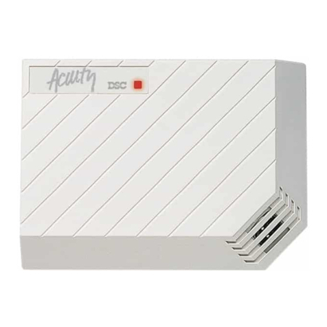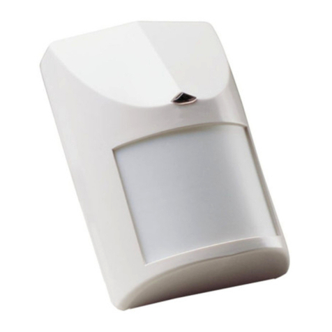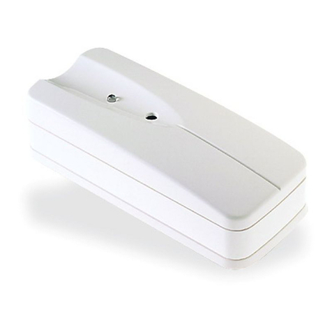
SETTING -UPTHEDETECTOR
LEDCONTROL
Switch1ofDIP-4.Use forSetting ”LED”-LEDEnable/Disable
Position Up“ON”-LEDENABLEThe REDLEDwill activatewhen the detectorisinalarmcondition.Position Down“OFF”-LEDDISABLE
The LED’saredisabled.
NOTE:the stateofthe switch“LED”-doesnotaffectthe operation ofthe relay.When an intrusion isdetected,the LEDwill activateand the alarm
relaywill switchintoalarmcondition for2sec.
ANTIMASKFUNCTION
Switch2ofDIP-4.Use forSetting “AM”-AntiMask function
Position Up“ON”-protection againstmasking the detectorfrom0.4mand closer.Position Down“OFF”-protection againstmasking the
detectorfrom0.8mand closer.
PIRSENSITIVITYADJUSTMENT
Switch3ofDIP-4.Use forSetting “PIR”-providessensitivitycontrolofPIRaccording tothe environment.
Position Up“ON”-gh sensitivityForstableenvironments.Position Down“OFF”-LowsensitivityForharshenvironments.Thissetting
enablesspecialsoftwaretomodifydetection speed.
PETIMMUNITYSETTING
Switch4ofDIP-4.Use forSettings“PET”15kg-25kg
Position Up“ON”Immunitytoan animalup to15 kgPosition Down"OFF”Immunitytoan animalup to25 kg
SENSITIVITYCALIBRATION
The MWpotentiometeradjuststhe detection sensitivityofDopplerbetween 40%and 100%(factorysetto65%).Rotatethe potentiometer
clockwisetoincreasesensitivity.Rotatethe potentiometercounter-clockwisetodecreasesensitivity.
The PIRpotentiometeradjuststhe detection range between 68%and 100%(factorysetto84%).Rotatethe potentiometerclockwisetoincrease
range,counter-clockwisetodecreaserange.
NOTE:You mustresetthe detectorfromControlPanelbeforethe newsettingswill takeeffect.
TEST PROCEDURE
Waitforone minutewarmup timeafterapplying 12 Vdcpower.Conducttesting withthe protected area cleared ofall people.
WALKTEST:1.Removefrontcover.SetLEDtoONposition.2.Reassemblethe frontcover.3.Startwalking slowlyacrossthe detection zone.
4.Observethatthe red LEDlightswhenevermotion isdetected.5.Allow5sec.between eachtestforthe detectortostabilize.6.Afterthe walk
testiscompleted,you can setthe LEDtoOFF position.
NOTE:Walktestsshouldbe conducted,atleastonceayear,toconfirmproperoperation and coverage ofthe detector.
TECHNICALSPECIFICATION
Detection Method Quad (Fourelement)PIR&
microwavepulseDoppler
PowerInput8.2to16 Vdc
CurrentDrawActive:25.5mA
Standby:18 mA
Temp.
Compensation YES
AlarmPeriod 2+/-1sec
AlarmOutputN.C28Vdc0.1Awith10 Ohm
seriesprotection resistors
TamperSwitch:N.C28Vdc0.1Awith10 Ohm
seriesprotection resistor-
open when coverisremoved
WarmUpPeriod 1min
LEDIndicator:
LED’sareblinking during warmup period
and selftesting,
RedLED:ONduring alarm
GreenLED:PIRCHANNEL
YellowLED:MWCHANNEL
Dimensions:118mm x62.5mm x41mm
(4.65”x2.46”x1.61”)
Weight: 120 gr.
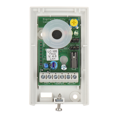
FIG 5-PCBLayout
PYROSENSORSWITCH FOR
SETTINGS
BLOCK CONNECTOR
FIG6
BracketInstallation
1
3
FIG7-Bracketoptions
Wall MountBracket
Ceiling MountBracket2
1
LIMITEDWARRANTY:DigitalSecurityControlsLtd,warrantsthatforaperiod of12 monthsfromthe dateofpurchase,the productshall be free ofdefectsinmaterialsandworkmanshipundernormaluseand thatinfulfillmentofany
breachofsuchwarranty.DigitalSecurityControlsLtdshall,atitsoption,repairorreplacethe defectiveequipmentupon returnsofthe equipmenttoitsrepairdepot. Thiswarrantyappliesonlytodefectsinpartsand workmanshipandnotto
damage incurred inshippingorhandling,ordamage due tocausesbeyond the controlofDigitalSecurityControlsLtd,suchaslightning,excessivevoltage mechanicalshock,waterdamage,ordamage arising outofabuse,alteration or
improperapplication oftheequipment.
Theforegoingwarrantyshall applyonlytothe originalbuyer,and isand shall be inlieu ofanyand all otherwarranties,whetherexpressed orimplied and ofallotherobligationsorliabilitiesonthepartofDigitalSecurityControlsLtd.Digital
SecurityControlsLtdneitherassumesresponsibilityfor,norauthorizesanyotherperson purporting toacton itsbehalftomodifyortochange thiswarranty,nortoassumeforitanyotherwarrantyorliabilityconcerning thisproduct.
InnoeventshallDigitalSecurityControlsLtdbe liableforanydirect,indirectorconsequentialdamages,lossofanticipatedprofits,lossoftimeoranyotherlossesincurredbythebuyerinconnection withthepurchase,installation oroperation
orfailureofthisproduct.
Motion detectorscan onlydetectmotion withinthe designated areasasShownintheirrespectiveinstallationinstructions.Theycannotdiscriminatebetweenintrudersand intended occupants.Motion detectorsdonotprovidevolumetricarea
protection.Theyhavemultiplebeamsofdetection and motion can onlybe detectedinunobstructedareascovered bythesebeams.Theycannotdetectmotion whichoccursbehind walls,ceilings,floor,closed doors,glasspartitions,glass
doorsorwindows.Any
type oftampering whetherintentionalorunintentionalsuchasmasking ,painting,orspraying ofanymaterialon the lenses,mirrors,windowsoranyotherpartofthe detection systemwill impairitsproperoperation.
Passiveinfraredmotion detectorsoperatebysensingchangesintemperature.Howevertheireffectivenesscan be reduced whentheambienttemperaturerisesnearorabovebodytemperatureorifthereareintentionalorunintentionalsources
ofheatinornearthedetectionarea.Someoftheseheatsourcescouldbeheaters,radiators,stoves,barbeques,fireplaces,sunlight, steamvents,lighting and soon.
WARNING:DigitalSecurityControlsLtd,recommendsthattheentiresystembecompletelytestedon aregularbasis.However,despitefrequenttesting,anddueto,butnotlimitedto,criminaltampering orelectricaldisruption,
itispossibleforthisproducttofail toperformasexpected.
Importantinformation:Changes ormodificationsnotexpresslyapprovedbyDigitalSecurityControlsLtdcouldvoidtheuser'sauthoritytooperatethisequipment.
2005 DigitalSecurityControlsLtd
Toronto,Canada
www.dsc.com


