manuals.online logo
Brands
  1. Home
  2. •
  3. Brands
  4. •
  5. jablotron
  6. •
  7. Security Sensor
  8. •
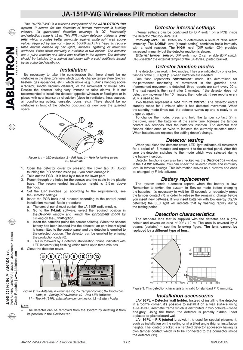
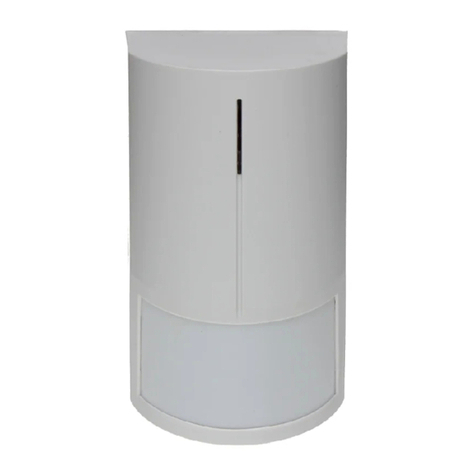
  9. jablotron JA-158P User manual

jablotron JA-158P User manual

JABLOTRON ALARMS a.s.
Pod Skalkou 4567/33 46601 Jablonec n. Nisou
Czech Republic www.jablotron.com
||
|
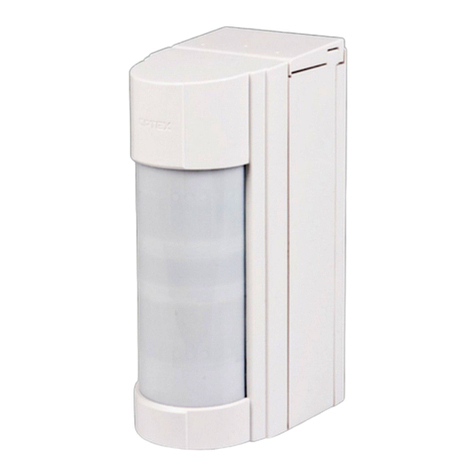
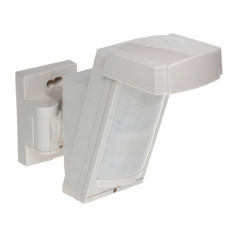
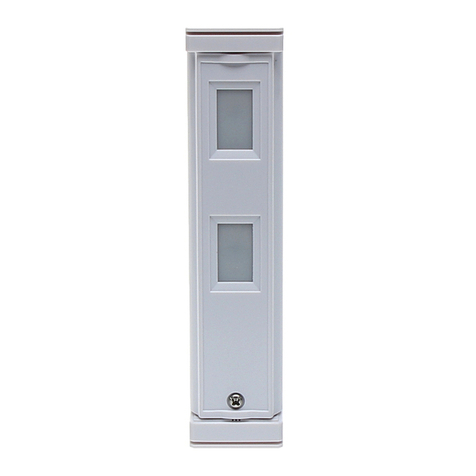
The JA-158P wireless outdoor PIR detector
The JA-158P wireless outdoor PIR detector 1 / 2 MMY51502
The JA-158P is an outdoor intruder wireless detector designed to detect
human body movement in a protected area. It supplements a double-zone
PIR sensor produced by Optex with a Jablotron transmitter enabling the
detector to be used within the JABLOTRON 100 system. The optical part of
the detector has 2 PIR sensors with non-overlapping 94 zone detection,
a high immunity to false alarms and the detection of small animals. The
detector includes an Antimasking function – protection against covering the
view and it also has two tampers (front and back) built-in. They immediately
report opening the detector or attempting tampering. The detector does
a self-test periodically and sends its status to the control panel. The detector
should be installed by a trained technician with a valid certificate issued by
an authorised distributor.
Installation
Choose a proper place for detector installation according to the following:
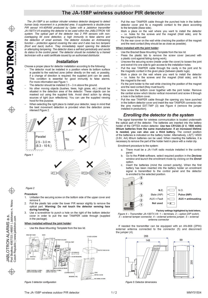
x The detector must be installed in a position where its bottom surface is
parallel to the watched zone (either directly on the wall, or possibly, if a
change of direction is required, the supplied joint can be used). This
condition is essential for good immunity to false alarms. For more
information see Figure 1.
x The detector should be installed 2.5 – 3 m above the ground.
x No other moving objects (bushes, trees, high grass, etc.) should be
situated in the detection area of the detector. These objects can be
masked out using the supplied foils. Avoid direct action by strong
sources of light (sun reflections). You can use the supplied viewing
hood for this purpose.
x When selecting the right place to install your detector, keep in mind
that the best movement detection is provided when the detection
zones intersect Figure 2.
Figure 1
Figure 2
Procedure:
1. Unfasten the securing screw on the bottom side of the upper cover
and remove it.
2. Pull the plastic tab under the lower PIR sensor slightly to remove the
optical part. Warning: Do not touch the detector sensing face
during handling.
3. Use a screwdriver to punch a hole on the right of the bottom detector
cover in order to pull the rear TAMPER cable through (supplied in the
package).
When installed without the joint holder:
x Use the Base Mounting Template from the box lid.
x Pull the rear TAMPER cable through the punched hole in the bottom
detector cover and fix a magnetic contact to the place according to
the template (Base side).
x Mark a place on the wall where you want to install the detector – i.e.
holes for the screws and the magnet (Wall side), and fix the magnet
to the wall.
x Fix the rear cover on the wall while checking the position of the
magnet and the reed contact (they should be as close as possible).
When installed with the joint holder:
x Use the Bracket Base Mounting Template from the box lid.
x Press the plastic tab to remove the screw cover (secured with
a plastic cord against falling during work).
x Unscrew the securing screw (inside under the cover) to loosen the
joint and swivel it to one side to gain access to the installation holes.
x Pull the rear TAMPER cable through the cavity in the joint and fix
the magnetic contact in the given place (between plastic lugs).
x Mark a place on the wall where you want to install the detector – i.e.
holes for the screws and the magnet (Wall side), and fix the magnet
to the wall.
x Fix the joint holder to the wall while checking the position of the
magnet and the reed contact (they must touch).
x Now screw the bottom cover together with the joint holder. Remove
the central screw which blocks vertical movement and screw
it through a hole in the bottom cover.
4. Pull the rear TAMPER cable through the opening you have punched in
the bottom detector cover and insert the rear TAMPER connector into
the pins marked EXT.TMP (3) see Figure 4 (remove the jumper
installed in production).
Enrolling the detector to the system
The signal transmitter for wireless communication is located underneath
the optical part of the detector. The batteries are inserted into the battery
holder of the OPTEX motion detector. Use two CR123A (3 V, 1500 mAh)
lithium batteries from the same manufacturer and replace both
batteries at the same time. If an increased lifetime is needed, you can
also use a third battery. The correct position of the batteries is indicated on
the battery holder. Alternatively, LS(T) 14500 (3.6V, AA) lithium batteries can
be used. When inserting the batteries, it is necessary to remove the part of
the holder held in place with a metal clip.
Enrollment procedure to the system:
a. There must be a JA-110R radio module installed in the control
panel.
b. Go to the F-link software, select required position in the Devices
window and launch the enrollment mode by clicking on the Enroll
option.
c. Insert the batteries (mind the correct polarity). When the first battery
has been inserted into the battery holder an enrollment signal is
transmitted to the control panel and the detector is enrolled to the
selected position.
N.C. N.O.
State (INP) Pulse (INP)
AUX = Fault AUX = antimasking
Not used
Factory settings highlighted by bold letters.
Figure 4 - Transmitter: 1 – terminals, 2 – option DIP switch, 3 – external
tamper connector, 4 – external antenna jumper, 5 – external antenna
connector
If needed the transmitter can be equipped with an AN-80 or AN-81
external antenna connected to the connector (5) and disconnect the
jumper (4).
Figure 3 detector configuration Figure 5: Detector dimensions
266
99
205
148
1234
ON
The JA-158P wireless outdoor PIR detector
The JA-158P wireless outdoor PIR detector 2 / 2 MMY51502
Setting up the optical part of the PIR
detector
The above-mentioned detection characteristics apply if the detector is
installed vertically in the guarded area. If a shorter detection range is
required, do not tilt the detector on the joint. Use the supplied self-adhesive
mask foils:
Masking using strips of the supplied foil can also be used to avoid
unwanted moving objects (e.g. a tree). Use the supplied protective hood for
protection against the sun and rain.
Setting up the electronic part of the PIR
detector
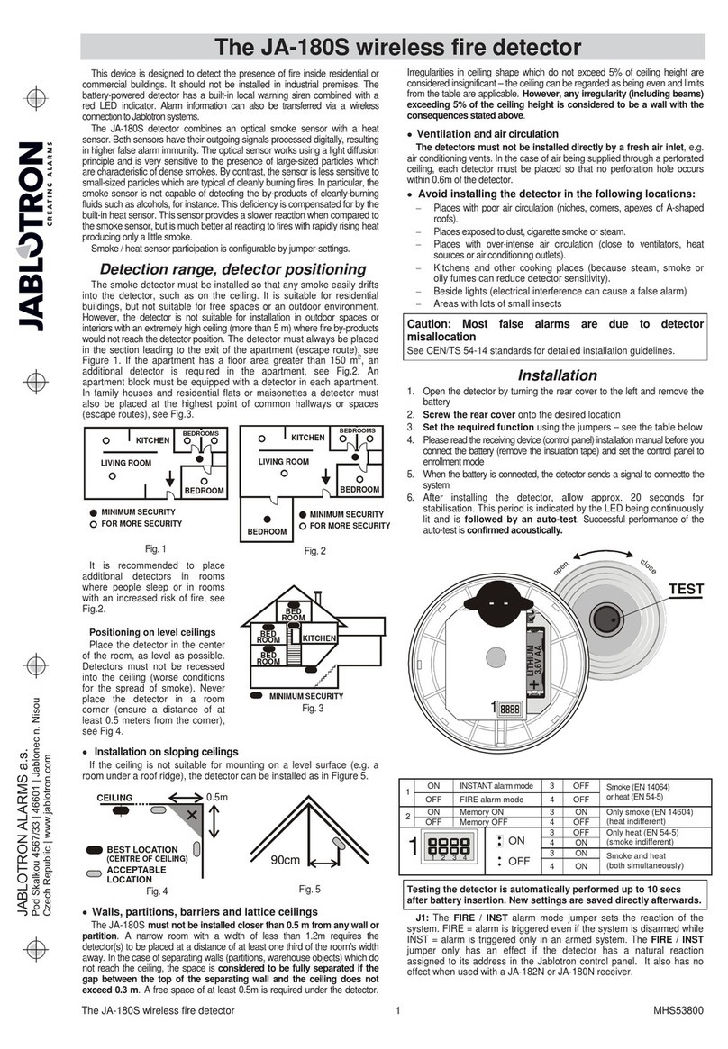
It is possible to set three levels of detector sensitivity using the switch on
the left of the bottom PIR – the levels are marked with letters:
L low – low sensitivity for places with false alarm risks
M middle – medium sensitivity
H high – high detection sensitivity
Other param eters can be set using the switches:
normal mode
test mode
save mode 120 s 5 s
standard immunity
high immunity
Fault output N.C. do not set this
do not set this fault is not alarm
LED disabled LED enabled
Area coverage test (DIP1) – the energy saving mode is not applied and
each detectable movement is indicated by an LED. The alarm is always
transmitted regardless of the energy saving mode settings (DIP2).
The energy saving mode (DIP2). When the detector is activated and
transmits the information to the control panel, it stops detecting motion in its
view for a set time. The activation of the LED (DIP6) serves as an
indication of the detector function – i.e. the area coverage. Disable the LED
to save the batteries in ordinary operation.
Testing
When the batteries are connected, the detector needs approx. 90 seconds
for stabilization. The LED keeps flashing all the time. Use the DIP switch 1 to
commence the area coverage test. Test the correct coverage of the guarded
area and whether the detector detects motion outside the guarded area.
Each movement is indicated by flashing detector LED and the information is
sent to the control panel.
When the test is finished to meet the declared battery lifetime, stop the
area coverage test, check whether the indication LED is off and set the
energy saving mode to 120 s.
Normal operating mode
Each time the detector is activated, the information is transmitted by a
radio signal. When the detector cover is opened or the detector is removed
from the bearing plate, a tamper signal is transmitted. The detector also
regularly (every 9 minutes) transmits control signals which serve the control
panel to check the presence and readiness of all devices in the installed
system.
The masking protection function
The detector has an anti-masking function – i.e. protection against
masking of the detector´s field of sight. If an object is detected in front of the
detector for more than three minutes, the detector sends a tamper signal.
Three short flashes of the LED indicate masking (the LED must be enabled).
When the object has been removed, the indication (tamper signal) ceases
after one minute.
It is possible to set three levels of this function using the switch on the right
of the bottom PIR – the levels are marked with letters:
HI high – high masking detection sensitivity
STD standard – standard masking detection sensitivity
OFF off – function disabled
Factory settings pre-set to STD.
Replacing the batteries
The detector checks battery status autom atically and if the batteries
are running low, it informs the system that they need replacing. The
detector remains fully functional. The batteries should be changed as
soon as possible (within 1 week).
Before battery replacement the control panel has to be switched to
service mode (see installation manual of the control panel) and then it is
possible to open the cover of the panel. Always use CR123A
(3 V, 1500 mAh) batteries or alternatively LS(T) 14500 (3,6 V AA)
batteries.
Note: Always use 2x lithium batteries. If needed put 3x batteries in to
increase the detector’s lifetime.
Technical specifications
Power: 2x Lithium battery type CR123A (3.0 V / 1.4 Ah)
Average battery lifetime 2 x (3 x) CR123A, approx. 3 years (4 years)*
Alternative power 2 x Lithium battery type CR14500 (AA) 3.6 V / 2.45 Ah
Average battery lifetime 2 x (3 x) CR14500, approx. 3 years (4 years)*
* valid for enabled 120 s saving mode
Please note: Batteries are not included
Communication band 868.1 MHz
RF range – distance from the control panel up to 300 m (open area)
Optex detector parameters
Detection characteristics 12 m / 85°; 94 segments
Recommended installation height 2.5 – 3.0 m
Object motion speed 0.3 – 1.5 ms-1
Battery saving timer adjustable 5 s or 120 s
Detector cover conformance IP55
Max. relative humidity of the environment 95%
Operational environment according to EN 50131-1 IV
Operating temperature range -20 °C to +60 °C
Security grade according to OPTEX
Complies with ETSI EN 300 220, EN 50130-4,
EN 55022, EN 60950-1
Weight 620 g
Can be operated according to ERC REC 70-03
JABLOTRON ALARMS a.s. hereby declares that the
JA-158P is in compliance with the essential requirements
and other relevant provisions of Directive 1999/5/EC and
2011/65/EU. The original of the conformity assessment can
be found at www.jablotron.com - Technical Support section.
Note: Although this product does not contain any harmful
materials we suggest you return the product to the dealer or
directly to the producer after use. For more detailed
information visit www.jablotron.com.
Other jablotron Security Sensor manuals

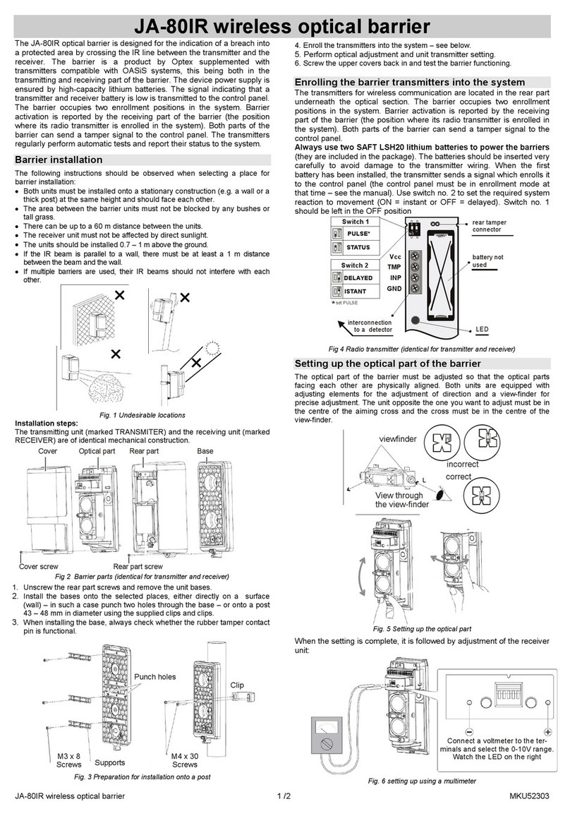
jablotron JA-84P User manual

jablotron

jablotron JA-84P User manual

jablotron JA-83P User manual

jablotron

jablotron JA-83P User manual

jablotron JB-EXT-TH-R User manual

jablotron

jablotron JB-EXT-TH-R User manual

jablotron JA-180PB User manual

jablotron

jablotron JA-180PB User manual

jablotron JA-160PC User manual

jablotron

jablotron JA-160PC User manual

jablotron JA-83M User manual

jablotron

jablotron JA-83M User manual

jablotron JA-152M User manual

jablotron

jablotron JA-152M User manual

jablotron JA-152P User manual

jablotron

jablotron JA-152P User manual

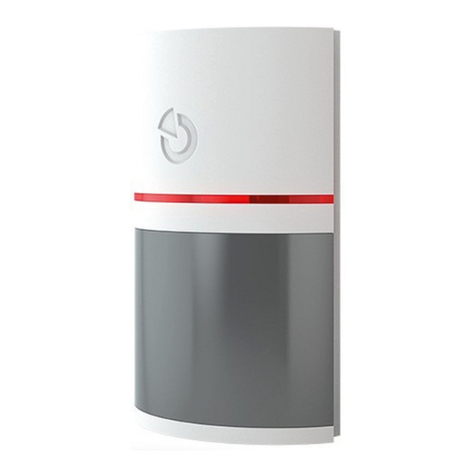
jablotron JA-151P-WG User manual

jablotron

jablotron JA-151P-WG User manual

jablotron JA-80PB User manual

jablotron

jablotron JA-80PB User manual

jablotron JA-151ST-A User manual

jablotron

jablotron JA-151ST-A User manual

jablotron JA-151P-WW User manual

jablotron

jablotron JA-151P-WW User manual

jablotron CA-550 User manual

jablotron

jablotron CA-550 User manual

jablotron JA-84P User manual

jablotron

jablotron JA-84P User manual

jablotron JA-120PC User manual

jablotron

jablotron JA-120PC User manual

jablotron JA-158P User manual

jablotron

jablotron JA-158P User manual

jablotron JA-80PB User manual

jablotron

jablotron JA-80PB User manual

jablotron GS-133 User manual

jablotron

jablotron GS-133 User manual

jablotron JA-188P User manual

jablotron

jablotron JA-188P User manual

jablotron JA-160PC User manual

jablotron

jablotron JA-160PC User manual

jablotron JA-87P User manual

jablotron

jablotron JA-87P User manual

jablotron JA-115P User manual

jablotron

jablotron JA-115P User manual

jablotron JA-111TH User manual

jablotron

jablotron JA-111TH User manual

jablotron JA-152SHM User manual

jablotron

jablotron JA-152SHM User manual

Popular Security Sensor manuals by other brands

B.E.G. LUXOMAT Indoor 180-M-2C Installation and operating instruction

B.E.G.

B.E.G. LUXOMAT Indoor 180-M-2C Installation and operating instruction

Emerson Dixell GDS41 Installing and operating instructions

Emerson

Emerson Dixell GDS41 Installing and operating instructions

Aritech 2000 Series Installation sheet

Aritech

Aritech 2000 Series Installation sheet

GreyScan ETD-100 Operator's manual

GreyScan

GreyScan ETD-100 Operator's manual

Risco ShockTec Plus Grade 3 installation instructions

Risco

Risco ShockTec Plus Grade 3 installation instructions

PCB Piezotronics 109C11/PCS-2AF Installation and operating manual

PCB Piezotronics

PCB Piezotronics 109C11/PCS-2AF Installation and operating manual

Korno GT-1000 SERIES user manual

Korno

Korno GT-1000 SERIES user manual

V-GREAT VG-6647 Installation and operation manual

V-GREAT

V-GREAT VG-6647 Installation and operation manual

BFT RIP installation manual

BFT

BFT RIP installation manual

Leica DIGICAT 500i quick start

Leica

Leica DIGICAT 500i quick start

D+H VRS 10 Original instructions

D+H

D+H VRS 10 Original instructions

Vertiv GEIST RTAFHD3 Quick installation manual

Vertiv

Vertiv GEIST RTAFHD3 Quick installation manual

Viking VSF303 Technical manual

Viking

Viking VSF303 Technical manual

DANLERS CEFPLL10VDC Installation notes

DANLERS

DANLERS CEFPLL10VDC Installation notes

iBeam TE-BPCIR product manual

iBeam

iBeam TE-BPCIR product manual

Honeywell Miller Titan TR50 user guide

Honeywell

Honeywell Miller Titan TR50 user guide

SICK deTem4 Core A/P operating instructions

SICK

SICK deTem4 Core A/P operating instructions

Honeywell 5800COMBO Installation and setup guide

Honeywell

Honeywell 5800COMBO Installation and setup guide

manuals.online logo
manuals.online logoBrands
  • About & Mission
  • Contact us
  • Privacy Policy
  • Terms and Conditions

Copyright 2025 Manuals.Online. All Rights Reserved.