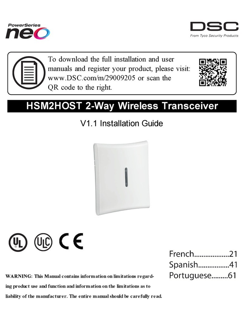
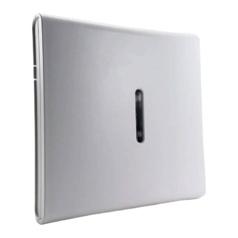
DSC HSM2HOST series User manual

HSM2HOST 2-Way Wireless Transceiver
V1.1 Installation Manual
WARNING: This manual contains information on limitations regarding product use and function and information on the
limitations as to liability of the manufacturer. The entire manual should be carefully read.

Table of Contents
Specifications and Features 3
Compatible Wireless Devices 4
Safety Instructions 5
Introduction 6
Installation Process Overview 6
Controls and Indicators 6
Tamper 7
Setup and Wiring 8
Mounting 8
Connect the HSM2HOST 8
Enroll The HSM2HOST 8
Delete the HSM2HOST 9
Permanently Mount 9
Other Options 9
Wireless Device Setup and Programming 10
[804][000] Enroll Wireless Devices 10
[804][001]-[716] Wireless Device Configuration 10
[804][801] RF Jam Detect 11
[804][802] Wireless Supervision Window 11
[804][810] Wireless Option 1 11
[804][841] Motion Cameras 12
[804][901]-[905] Delete Wireless Devices 12
[804][921]-[925] Replace Wireless Devices 12
[804][990][001 – 005] Show All Devices 13
[804][999] Reset to Factory Defaults 13
[904] Placement Testing Wireless Devices 13
Programming Worksheets 15
Label Programming 15
[804] Wireless Programming 17
[804][000] Wireless Device Enrollment – Zones 18
[804][000] Wireless Device Enrollment – Wireless Keys 19
[804][000] Wireless Device Enrollment – Wireless Sirens 19
[804][000] Wireless Device Enrollment – Wireless Keypads 20
[804][000] Wireless Device Enrollment – Wireless Repeaters 20
[804][001]-[128] Configure Wireless Zones 1-128 (copy as needed) 21
[804][551]-[556] Configure Wireless Sirens 1-16 (copy as needed) 22
Toggle Options 22
Toggle Options 23
[804][601]-[632] Configure Wireless Keys (copy as needed) 23
[601]-[632] Wireless Key 1-32 24
[804]-[701]-[716] Wireless Keypad Programming (copy as needed) 24
[804][801] Jam Detect 26
[804][802] Supervisory Window 26
[804][810] Wireless Options 26
FCC Compliance Statement 30

3
Specifications and Features
lCurrent Draw: 60mA
lVoltage: Draws current from the PowerSeries Neo alarm controller (10.8VDC to 12.5VDC) - (Lim-
ited Power Supply)
lFrequency: 433MHz (HSM2HOST4), 868MHz (HSM2HOST8), 912-919MHz (HSM2HOST9UL)
lZones - can receive signals from up to 128 wireless zones, plus 16 wireless keypads. Also supports
up to 32 wireless keys or 32 panic pendants and 16 sirens
lSupervisory - programmable supervisory window
lCan be wired up to 1000 ft. / 230 m from the main panel with 22 AWG wire
lConnects to Corbus
lCompatibility: The HSM2HOST is used with PowerSeries Neo alarm panels
lOperating temperature: NA= 0°C – +49°C (32-122°F); EU= -10°C – +55°C
lRelative humidity: 93% non-condensing
lSeparate, built-in wall and case tampers
Note: For Commercial BURG (UL) the Supervisory window shall be set to 4 hours.
For Residential Fire (UL/ULC) the Supervisory window shall be set to 200 seconds.
For Residential BURG (UL/ULC) the supervisory window shall be set to 24 hours.
For UL Home Healthcare applications the supervisory window shall be set to 24 hours
Only models operating in the band 912-919 MHz are UL/ULC listed where indicated. Only UL
approved devices are to be used with UL/ULC listed systems.
HSM2HOST Installation Manual

4
Compatible Wireless Devices
The HSM2HOSTx (x= 4/8/9) can receive signals from the devices listed in the following chart. Please
refer to the instruction sheet of the device for operating instructions. Throughout this document, x in the
model number represents the operating frequency of the device as follows: 9 (912-919 MHz), 8
(868MHz), 4 (433MHz).
Alarm Controllers
PowerSeries Neo alarm controllers HS2128/
HS2064/
HS2032/
HS2016
Modules
Wireless Keypads HS2LCDWFx
HS2LCDWFPx
HS2LCDWFPVx
Wireless Devices
Wireless PG smoke detector PGx926UL
Wireless PG smoke and heat detector PGx916UL
Wireless PG CO detector PGx913
Wireless PG PIR motion detector PGx904(P)UL
Wireless PG PIR + camera motion detector PGx934(P)UL
Wireless Outdoor PG PIR + camera motion detector PGx944
Wireless PG curtain motion detector PGx924UL
Wireless PG dual tech motion detector PGx984(P)
Wireless PG mirror motion detector PGx974(P)UL
Wireless PG outdoor motion detector PGx994UL
Wireless PG glass break detector PGx912
Wireless PG shock detector PGx935UL
Wireless PG flood detector PGx985UL
Wireless PG temperature detector (indoor use) PGx905UL
Wireless PG key PGx939UL
Wireless PG key PGx929UL
Wireless PG panic key PGx938UL
Wireless PG 2-button key PGx949UL
Wireless PG indoor siren PGx901UL
Wireless PG outdoor siren PGx911UL
Wireless PG repeater PGx920UL
Wireless PG door/window contact PGx975UL
Wireless PG door/window contact w/ AUX PGx945UL
Compatible Wireless Devices

5
Safety Instructions
lThis equipment must be installed by Service Persons only (a service person is defined as a person
having the appropriate technical training and experience necessary to be aware of hazards to
which that person may be exposed in performing a task and of measures to minimize the risks to
that person or other persons). It must be installed and used within a non-hazardous, indoor envir-
onment only (pollution degree max 2, over voltages category II).
lThe installer is responsible for instructing the system user in regards to electrical safety precautions
when using a system which includes this equipment and also in regards to each of the following:
lDo not attempt to service this product. There are no user serviceable parts inside. If ser-
vicing is required, it shall be referred to service persons only.
lUsing adequate mounting means (e.g., plastic/metal anchors), secure the transceiver to the building
structure before applying power.
lInternal wiring must be routed in a manner that prevents:
lExcessive strain on wire and on terminal connections;
lLoosening of terminal; connections;
lDamage to conductor insulation.
Only UL/ULC listed devices can be used in UL/ULC listed installations.
HSM2HOST9 is listed for UL Commercial Burglary, Residential Fire, Residential Burglary and Home
Health Care, ULC Residential Fire and Residential Burglary:
UL1610 Central-Station Burglar Alarm Units
UL1023 Household Burglar-Alarm System Units
UL985 Household Fire Warning System Units
UL1637 Home Health Care Signaling Equipment
ULC-S545-02 Residential Fire Warning System Control Units
ORD-C1023-1974 Household Burglar-Alarm System Units
UL 609 Local Burglar Alarm Units and Systems
UL365 Police Station Connected Burglar Alarm Units and Systems
HSM2HOST Installation Manual

6
Introduction
The HSM2HOSTx two-way wireless transceiver adds wireless capability to PowerSeries Neo alarm con-
trollers, model HS2128, HS2064, HS2032 or HS2016. The HSM2HOST receives signals from wireless
zones and wireless keys, and provides information to the alarm controller it is connected to. This manual
describes how to install, program and maintain the HSM2HOST. Note that only one HSM2HOST or one
RFK keypad can be enrolled on the alarm system.
Before installing:
1. Plan the placement and wiring of the security system (see system installation manual).
2. Install the control panel and optional modules.
3. Temporarily mount all wireless devices in the intended location.
Installation Process Overview
To install and set up the HSM2HOST and wireless devices:
1. Temporarily mount and wire the HSM2HOST module (See "Mounting" on page 8).
2. Enroll the HSM2HOST and first wireless keypad (See "Enroll The HSM2HOST" on page 8).
3. Check the location for RF interference levels (See "[804][801] RF Jam Detect" on page 11).
4. Enroll wireless devices (See "[804][000] Enroll Wireless Devices" on page 10).
5. Complete zone and other programming on the system (See "Wireless Device Setup and Pro-
gramming" on page 10).
6. Test the placement of all the wireless devices (See "[904] Placement Testing Wireless Devices" on
page 13).
7. Permanently mount the HSM2HOST and wireless devices (See "Permanently Mount" on page 9).
Controls and Indicators
Status LEDs
The LEDs on the front of the HSM2HOST provide feedback regarding the installation, operation and
troubleshooting of the unit. The LEDs function as follows:
Red LED Operation
Module Power Up: On steady during module power-up sequence then off.
Firmware Update: Slow flashing = update in progress
Rapid flashing = update failed
Trouble Condition: lNo trouble: 1 rapid flash every 10 seconds.
If troubles are present, a series of flashes occur every 2 seconds. Each series
of flashes indicate troubles as follows:
l1 flash: Module not enrolled
l2 flashes: Loss of contact with module for over 60 seconds
l3 flashes: Corbus low voltage
l8 flashes: RF interference (jam condition)
Module Con-
firmation:
Flashes rapidly during module confirmation process.
Placement Test: On steady when location is bad. Off when location is good.
Green LED Operation
Placement Test: On steady when location is suitable. Off when location is unsuitable.
Note: For UL/ULC listed systems, signal must be “Strong”. See Wireless Device
Status Indications on page 10 for details.
Introduction

7
Tamper
The HSM2HOST has separate built-in wall and case tampers. The case tamper is disabled by default on
the NA version (enabled on EU version).
Section [804][810] option 3 enables or disables the case tamper. Enable or disable the wall tamper by
fastening the breakaway wall tamper bracket securely to the wall using one of the supplied screws.
The case tamper activates when the case is opened and restores when the case is closed. The wall tamper
on the back of the unit is depressed by the mounting surface when properly installed. If the unit is
removed, the tamper activates. Ensure the mounting surface is smooth and free of obstructions that block
access to the rear of the unit. Electrical wires should not run over or under the module when it is moun-
ted.
Note: The built in wall and case tamper must be installed and enabled for UL/ULC listed Commercial/
Residential Burglary applications.
HSM2HOST Installation Manual

8
Setup and Wiring
This section describes how to set up and wire the HSM2HOST module.
Mounting
Note: Permanently mount the HSM2HOST receiver and wireless devices AFTER placement testing each
device (See "[904] Placement Testing Wireless Devices" on page 13).
Find a place that is:
ldry,
lwithin operating temperature range,
lcentral to the proposed placement of all wireless devices,
las high as possible. The range is reduced if mounted below ground level,
lfar from sources of interference, including: electrical noise (computers, televisions, electric motors,
appliances, heating and air conditioning units), large metal objects like heating ducts and plumb-
ing which may shield the electro-magnetic waves,
lsmooth and free of obstructions that block access to the rear of the unit.
Connect the HSM2HOST
Caution: Remove all power (AC, DC, telephone lines) from the system while connecting modules to the
Corbus.
To connect the HSM2HOST:
1. With the alarm panel powered down, connect the HSM2HOST to the four-wire Corbus of the
alarm panel according to Figure 1.
2. Once the wiring is complete, power up the security system.
Figure: 1 Wiring Diagram
Enroll The HSM2HOST
The HSM2HOST must be enrolled onto the alarm panel before any wireless devices can be enrolled.
When the alarm system is powered up for the first time, the first keypad or the HSM2HOST (if using a
wireless keypad as the first keypad) can be enrolled.
To do this:
1. Once the HSM2HOST is wired to the alarm panel and power has been applied, power up a wire-
less keypad.
2. Press any button on the keypad to enroll it on the HSM2HOST. The HSM2HOST is then auto-
matically enrolled on the alarm panel.
Alternately, enroll the HSM2HOST on the system at any time using the following procedure:
1. Enter Installer Programming section [902][000] (Auto Enroll All Modules). Modules are auto-
matically detected in the following order:
1– Keypads
2 – Zone Expander
Setup and Wiring

9
3 – Output Module
4 – HSM2HOSTx
5 – Audio Verification Module
6 – Power Supply 1A
2. When prompted, press [*] to enroll.
Or another Alternate method,
1. Enter Installer Programming section [902][001] (Enroll Modules).
2. When prompted, key in the serial number found on the back of the module. The module is
enrolled.
Delete the HSM2HOST
To remove the HSM2HOST from the system:
1. Enter Installer Programming section [902][106] (Delete HSM2HOSTx).
2. Press [*] to delete.
Permanently Mount
Once a suitable location is found, mount the HSM2HOST as follows:
1. Pull the Corbus wires through the holes at the back of the cabinet.
2. Mount the cabinet securely to the wall using the three screws supplied.
3. To enable the wall tamper, fasten the breakaway wall tamper bracket securely to the wall using
the supplied screw.
Figure: 2 Mounting the HSM2HOST
Other Options
The following actions may be performed on the HSM2HOST:
Section Action
[902][106] Delete the HSM2HOST from the alarm system.
[903][106] Confirm that the HSM2HOST is enrolled.
[000][806] Add a label to appear on LCD keypads.
[900][461] View HSM2HOST model information.
HSM2HOST Installation Manual

10
Wireless Device Setup and Programming
This section describes how to enroll and program wireless devices such as contacts, motion sensors and
sirens on the alarm panel.
[804][000] Enroll Wireless Devices
Once the HSM2HOST is installed and enrolled on the alarm panel, wireless devices can be enrolled using
the following method:
1. Enter Installer Programming section [804][000].
2. When prompted, either activate the device (see device installation sheet) to enroll immediately or
enter a device ID number. Do the latter to pre-enroll devices then enroll them later at the customer
site. The alarm panel determines the type of device being enrolled and presents the appropriate pro-
gramming options.
Device Type Programming Options
Zone (01) Zone type
(02) Partition assignment
(03) Zone label
Wireless Key (01) Partition assignment
(02) User label
Siren (01) Partition assignment
(02) Siren label
Repeater (01) Repeater label
Wireless Device Options
3. Use the scroll keys or type in the corresponding number to select an option.
4. Scroll through the available selections, key in a number or enter text as appropriate.
5. Press [*] to accept and move to the next option.
6. Once all options are configured, the system prompts to enroll the next device.
7. Repeat the process described above until all wireless devices are enrolled.
Note: The configuration options listed above can be modified using [804][911] Modify Device.
[804][001]-[716] Wireless Device Configuration
To configure wireless devices:
1. Enter Installer Programming section [804] then select one of the following sub-sections:
l001-128 – Configure Wireless Zones
l551-566 – Configure Wireless Sirens
l601-632 – Configure Wireless Keys
l701-716 – Configure Wireless Keypads
2. Select a device to configure using the scroll keys or go directly to a specific device by entering a
hotkey.
3. Use the scroll buttons or enter a hotkey to select a configuration option for the device. See device
sheets for details.
4. Press [*] to accept and move to the next option.
5. Once all options are configured, the system returns to the base configuration menu.
6. Repeat the process described above to configure other wireless devices.
Wireless Device Setup and Programming

11
[804][801] RF Jam Detect
RF jam detection (continuous interfering transmissions on the radio network) can be turned on or off.
When on, RF jamming is logged and reported.
To configure RF jamming:
1. Enter Installer Programming section [804][801] then select one of the following options:
00 Disabled Jamming detection and reporting is enabled/disabled Note: Must be Enabled
for UL/ULC listed installations.
01 UL 20/20-
USA
Continuous RF jamming for 20 seconds
02 EN 30/60-
Europe
30 seconds of accumulated jamming within 60 seconds
03 Class 6 30/60-
British
As EN (30/60) but reported only if the jamming duration exceeds 5 minutes
2. Press [*] to accept the selection.
3. Press [#] to exit the section.
[804][802] Wireless Supervision Window
This option is used to program the length of time a wireless device can be absent from the system before a
fault is generated.
For EN installations, 1 hour or 2 hours must be selected.
When option 06 is used, which configures the system to generate fault conditions after a device has been
detected as absent for 24 hours, smoke detectors generate a fault condition after a maximum of 18 hours
when the 200s supervision toggle option is disabled.
To program the Wireless Supervisory Window:
1. Enter Installer Programming section [804][802].
2. Select one of the following options by scrolling or entering the hotkey:
l00 – Disabled
l01 – After 1 Hour
l02 – After 2 Hour
l03 – After 4 Hour
l04 – After 8 Hours
l05 – After 12 Hours
l06 – After 24 Hours
3. Press [*] to accept the selection.
4. Press [#] to exit the section.
Note: For UL Residential Burglary (UL1023), Home Health Care (UL1637), ULC Residential Burglary
(ULC/ORD-C1023) installations, the maximum Supervision window shall be set to 24 hours.
For UL Residential Fire (UL985) installations, the maximum supervision window is set to 200s.
For UL Commercial Burglary (UL1610/UL365) and ULC Residential Fire (ULC-S545), the maximum
supervision window shall be set to 4 hours.
[804][810] Wireless Option 1
To program wireless options:
1. Enter Installer Programming section [804][810].
2. Select one of the following options by scrolling or entering the hotkey:
HSM2HOST Installation Manual

12
01 RF Delin-
quency
On: the system cannot be armed if a wireless supervisory trouble exists.
An RF delinquency trouble is generated.
Off: wireless supervisory troubles do not prevent arming.
02 Wireless
Supervisory/
RF Jam
Alarm
On: if a supervisory or jamming trouble occurs during Away arming, the
siren activates and the event is logged and reported.
Off: supervisory or RF jam troubles during Away arming do not activate
the siren or get logged and reported.
03 Wireless
Tamper
On: module tampers are logged and reported.
Off: module tampers are not logged or reported.
04 Fire Super-
vision
On: fire devices are supervised every 200 seconds. If the device fails to
report within this window, a supervision trouble is generated.
Off: fire devices follow the supervision window programmed in section
802, up to a maximum of 18 hours. The supervisory window can be pro-
grammed with a higher value, but detectors still go into fault after 18
hours.
3. Press [*] to accept the selection and [#] to exit.
[804][841] Motion Cameras
To program motion cameras:
1. Enter Installer Programming section [804][841].
2. Select one of the following options by scrolling or entering the hotkey:
[001] Visual Verification On: Alarms trigger image capture from PIR Cameras
Off: Alarms do not trigger image capture from PIR Cameras
[002] View Time Window 01 Alarm + 5 Minutes
02 Alarm + 15 minutes
03 Alarm + 1 Hour
[003] View Other Alarms 01 Fire key enabled/disabled
02 Duress enabled/disabled
03 Medical key enabled/disabled
04 Panic key enabled/disabled
[804][901]-[905] Delete Wireless Devices
To delete wireless devices:
1. Enter Installer Programming section [804] then select one of the following sub-sections:
[901] – Delete wireless zone devices
[902] – Delete wireless key
[903] – Delete sirens
[904] – Delete repeaters
[905] – Delete keypads
2. Select a device to delete using the scroll keys or go directly to a specific device by entering a
hotkey.
3. Press [*] to delete or [#] to exit.
[804][921]-[925] Replace Wireless Devices
Use this option to replace a faulty device enrolled on the system with another device of the same type
while maintaining the configuration of the original. The faulty device does not need to be deleted.
[804][841] Motion Cameras

13
To replace a wireless device:
1. Enter Installer Programming section [804] then select one of the following sub-sections:
[921] – Replace wireless zone devices
[922] – Replace wireless key
[923] – Replace sirens
[924] – Replace repeaters
[925] – Replace keypads
2. Press [*] to select a sub-section. The first available device is displayed.
3. Select a device to replace using the scroll keys or go to a specific device by entering a hotkey.
4. Press [*]. When prompted, activate the device (full enrollment) or enter the device ID (pre-enroll-
ment). A message is displayed confirming enrollment.
[804][990][001 – 005] Show All Devices
Use this section to review wireless devices enrolled on the system and to view serial numbers associated
with each device.
To review wireless device information:
1. Enter Installer Programming section [804][990] then select one of the following sub-sections:
l[001] – All zones
l[002] – Repeaters
l[003] – Sirens
l[004] – Wireless keys
l[005] – keypads
2. Press [*] to select a wireless device type. The first available device is displayed.
3. Use the scroll keys to view the enrolled devices.
Note: This option is not fully supported by LED and ICON keypads.
[804][999] Reset to Factory Defaults
Selecting this option resets HSM2HOST programming to factory default settings.
[904] Placement Testing Wireless Devices
This test is used to determine RF signal status for wireless devices and can be performed at a system
keypad or at the individual device. These instructions pertain to testing at the keypad. For instructions on
placement testing at the device, refer to the installation sheet provided with the wireless equipment. The
following test modes are available:
[904][001]-[128] Test wireless zones Test wireless devices individually by zone. Zones with
vanishing contacts must be activated to placement test.
[904][521]-[528] Test all repeaters Test each enrolled wireless repeater. 521-528 for repeat-
ers 1-8
[904][551]-[566] Test all sirens Test each enrolled wireless siren. 551-566 for sirens 1-
16
[904][601]-[632] Test all wireless keys Test individual wireless keys. Once in this section,
press a button on the wireless key to begin the test.
601-632 for wireless keys 1-32.
[904][701]-[716] Test all keypads Test each enrolled keypad. 701-716 for keypads 1-16
Two test results are provided:
l24-hour: Average results of signal strength testing over a 24-hour period.
lNow: Signal status results of the current test.
A flashing Trouble LED indicates RF interference. The following status indicators may be displayed:
HSM2HOST Installation Manual

14
LCD Icon* LED+ Status
Strong 1 9 Strong signal strength
Good 2 10 Good signal strength
Poor 3 11 Poor signal strength
Not Test 5 13 Displayed as the Now result if no test was performed
Not Test 5 13 Always displayed as the 24-hour result when testing wireless keys
*For Icon keypads, digit 1 indicates 24-hour test results; digit 2 indicates Now test results.
+For LED keypads, the first digit indicates 24-hour results; the second digit indicates Now test results.
Note: For EN/UL/ULC installations, only STRONG signal levels are acceptable.
[904] Placement Testing Wireless Devices

15
Programming Worksheets
Use these pages for recording custom programming options (Installers Programming: [*][8]).
[902] Enroll Module 000 - Auto Enroll
001 - Enroll Modules
002 - Module Slot Assignment (LED/ICON)
003 - Module Slot Assignment (LED only)
Delete Module 101 - Delete Keypads
102 - Delete Zone Expander
103 - Delete Output Expander
106 - Delete HSM2HOST
108 - Delete Audio Verification
109 - Delete Power Supply
[903] Confirm Module 001 - Confirm Keypad
002 - Confirm Zone Expander
003 - Confirm Output Expander
006 - Confirm HSM2HOST
008 - Confirm Audio Verification
009 - Confirm Power Supply
Label Programming
[000] Module Lables
[801] Keypad Label (1 x 14 Characters)
001: 009:
002: 010:
003: 011:
004: 012:
005: 013:
006: 014:
007: 015:
008: 016:
HSM2HOST Installation Manual

16
[802] Zone Expander Label (1 x 14 Characters)
001: 009:
002: 010:
003: 011:
004: 012:
005: 013:
006: 014:
007: 015:
008: 016:
[803] Output Expander Label (1 x 14 Characters)
001: 009:
002: 010:
003: 011:
004: 012:
005: 013:
006: 014:
007: 015:
008: 016:
[806] HSM2HOST Label (1 x 14 Characters)
01:
[809] HSM2300 Power Supply Label (1 x 14 Characters)
01:
02:
03:
04:
[810] HSM2204 High-Current Output Label (1 x 14 Characters)
01:
02:
03:
04:
Label Programming

17
[820] Siren Labels (1 x 14 Characters)
01:
02:
03:
04:
05:
06:
07:
08:
[821] Repeater Labels (1 x 14 Characters)
01:
02:
03:
04:
05:
06:
07:
08:
[804] Wireless Programming
[000] Enroll Wireless Device
Zone
Wireless Key
Siren
Keypad
Repeater
HSM2HOST Installation Manual

18
[804][000] Wireless Device Enrollment – Zones
Zone Label Zone Defin-
ition
Zone
Type Partition
[804][000] Wireless Device Enrollment – Zones

19
[804][000] Wireless Device Enrollment – Wireless Keys
Key# Partition# User Label Key# Partition# User Label
1 17
2 18
3 19
4 20
5 21
6 22
7 23
8 24
9 25
10 26
11 27
12 28
13 29
14 30
15 31
16 32
[804][000] Wireless Device Enrollment – Wireless Sirens
WLS
Siren# Partition# Siren Label WLS
Siren# Partition# Siren Label
1 9
2 10
3 11
4 12
5 13
6 14
7 15
8 16
HSM2HOST Installation Manual

20
[804][000] Wireless Device Enrollment – Wireless Keypads
WLS
Keypad#
Keypad
Assignment Keypad Label WLS
Keypad#
Keypad
Assignment Keypad Label
1 9
2 10
3 11
4 12
5 13
6 14
7 15
8 16
[804][000] Wireless Device Enrollment – Wireless Repeaters
Repeater# Repeater Label
1
2
3
4
5
6
7
8
[804][000] Wireless Device Enrollment – Wireless Keypads
Other manuals for HSM2HOST series
3
Table of contents
Other DSC Transceiver manuals