66
66
6
Section 5 - Installing a Skyroute Transceiver
TT
TT
Timeime
imeime
ime--
--
-Saving TSaving T
Saving TSaving T
Saving Tips: By powering up the Skips: By powering up the Sk
ips: By powering up the Skips: By powering up the Sk
ips: By powering up the Skyroute transceiver on a battery alone (battery ryroute transceiver on a battery alone (battery r
yroute transceiver on a battery alone (battery ryroute transceiver on a battery alone (battery r
yroute transceiver on a battery alone (battery red to Bell In and Ked to Bell In and K
ed to Bell In and Ked to Bell In and K
ed to Bell In and Keybus reybus r
eybus reybus r
eybus red,ed,
ed,ed,
ed,
battery black to Kbattery black to K
battery black to Kbattery black to K
battery black to Keybus black), you can quickly determine a location whereybus black), you can quickly determine a location wher
eybus black), you can quickly determine a location whereybus black), you can quickly determine a location wher
eybus black), you can quickly determine a location where your signal stre your signal str
e your signal stre your signal str
e your signal strength is strong prior to installingength is strong prior to installing
ength is strong prior to installingength is strong prior to installing
ength is strong prior to installing
the unit. The Skthe unit. The Sk
the unit. The Skthe unit. The Sk
the unit. The Skyroute unit does not have to be active to show signal stryroute unit does not have to be active to show signal str
yroute unit does not have to be active to show signal stryroute unit does not have to be active to show signal str
yroute unit does not have to be active to show signal strength.ength.
ength.ength.
ength.
5 .1 Location of the Skyroute Unit
It is very important to determine the best location for maximum signal strength.
Verify signal strength prior to installation!
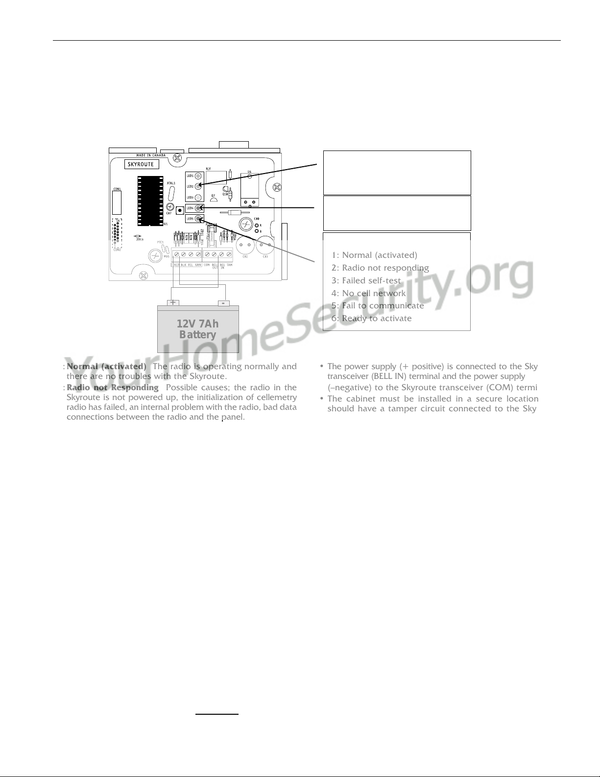
1:Normal (activated) The radio is operating normally and
there are no troubles with the Skyroute.
2:Radio not Responding Possible causes; the radio in the
Skyroute is not powered up, the initialization of cellemetry
radio has failed, an internal problem with the radio, bad data
connections between the radio and the panel.
3:Failed self-test A self-test of the cellemetry module has
failed.
4:No cell network The cellemetry modem has failed to
register with the cellular network (Ie. no network coverage
or very weak signal).
5:Failure to communicate The Skyroute has not successfully
communicated a signal to the central station (the Skyroute
has not received the acknowledgement that the central
station successfully received a signal).
6:Ready to Activate The Skyrotue has not been activated
with Connect 24.
• If there is a Skyroute trouble, the panel it is connected to
will display a ‘General System Supervisory’ trouble.
• If the [TAM] to [COM] terminals are open on the Skyroute,
the panel it is connected to will display a ‘General System
Tamper’ trouble.
5.2 Relocating the Skyroute Transceiver
Since the Skyroute transceiver is a Keybus accessory, it is
possible to relocate the module up to 1000 feet from the
main control panel when the panel is not located in a good
Cellemetry coverage area (a control panel installed in a
vault for example). When relocating the module, follow
theses rules:
• Maximum of 1000 feet from the main control. Keybus
(Red, Black, Yellow, Green) from the panel to the Skyroute
transceiver.
for UL installations.
• The power supply (+ positive) is connected to the Skyroute
transceiver (BELL IN) terminal and the power supply
(–negative) to the Skyroute transceiver (COM) terminal.
• The cabinet must be installed in a secure location and
should have a tamper circuit connected to the Skyroute
(TAM and COM) terminals.
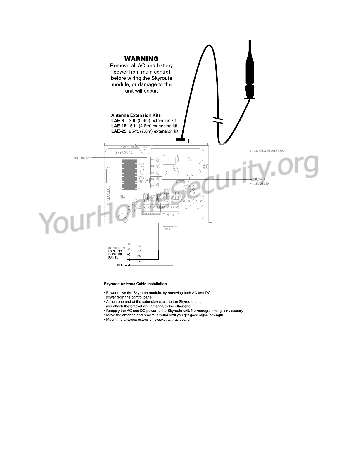
5.3 Relocating the Antenna
If a suitable location is not available for proper Cellemetry
coverage, obtain an Antenna Extension Bracket Kit from your
DSC supplier. Each kit contains an extension cable, a mount-
ing bracket, instructions, and all required hardware. Three
lengths of extension cable are available:
Extension Kit Length of cable
LAE-3 3 feet (0.91 m)
LAE-15 15 feet (4.57 m)
LAE-25 25 feet (7.62 m)
Only use the Extension Kits to extend the mounting range of
the antenna. Do not cut or splice the extension cable. The
maximum distance between the Skyroute transceiver and the
antenna is 25 feet (7.62 m) as obtained by using the LAE-25
Extension Kit. Make sure the antenna is in a physically secured
location to avoid tampering.
Secure the TNC connector from the Extension Kit to the
mounting bracket, ensuring that the star washers make solid
electrical contact with the mounting bracket.
Remove the antenna from the Skyroute module and connect
the extension cable to the TNC connector on the module.
Secure the antenna to the TNC connector mounted on the
Extension Kit mounting bracket. Locate the mounting bracket
and antenna away from possible sources of electrical interfer-
ence. Moving the antenna just a short distance will likely be
adequate. Temporarily secure the mounting bracket in the
new location and proceed with testing. If the test is success-
ful, permanently secure the mounting bracket and antenna at
the new location.
LED 1: Good signal strength
LED 2: Acceptable signal strength
LED 3: Poor signal strength
LED 4: One blink = Transmit TX
Two blinks = Receive RX
LED 5: Status (number of blinks)
1: Normal (activated)
2: Radio not responding
3: Failed self-test
4: No cell network
5: Fail to communicate
6: Ready to activate
+-
12V 7Ah
Battery