55
55
5
Section 6 - Installing a Skyroute
maxmax
maxmax
max
transceiver
Time-Saving Tips: By powering up the Skyroute maxTime-Saving Tips: By powering up the Skyroute max
Time-Saving Tips: By powering up the Skyroute maxTime-Saving Tips: By powering up the Skyroute max
Time-Saving Tips: By powering up the Skyroute maxxon a battery alone (battery red to Bell and Combus red, batteryon a battery alone (battery red to Bell and Combus red, battery
on a battery alone (battery red to Bell and Combus red, batteryon a battery alone (battery red to Bell and Combus red, battery
on a battery alone (battery red to Bell and Combus red, battery
black to Combus black), you can quickly determine a location where your signal strength is strong prior to installing theblack to Combus black), you can quickly determine a location where your signal strength is strong prior to installing the
black to Combus black), you can quickly determine a location where your signal strength is strong prior to installing theblack to Combus black), you can quickly determine a location where your signal strength is strong prior to installing the
black to Combus black), you can quickly determine a location where your signal strength is strong prior to installing the
unit. The Skyroute max does not have to be active to show signal strength.unit. The Skyroute max does not have to be active to show signal strength.
unit. The Skyroute max does not have to be active to show signal strength.unit. The Skyroute max does not have to be active to show signal strength.
unit. The Skyroute max does not have to be active to show signal strength.
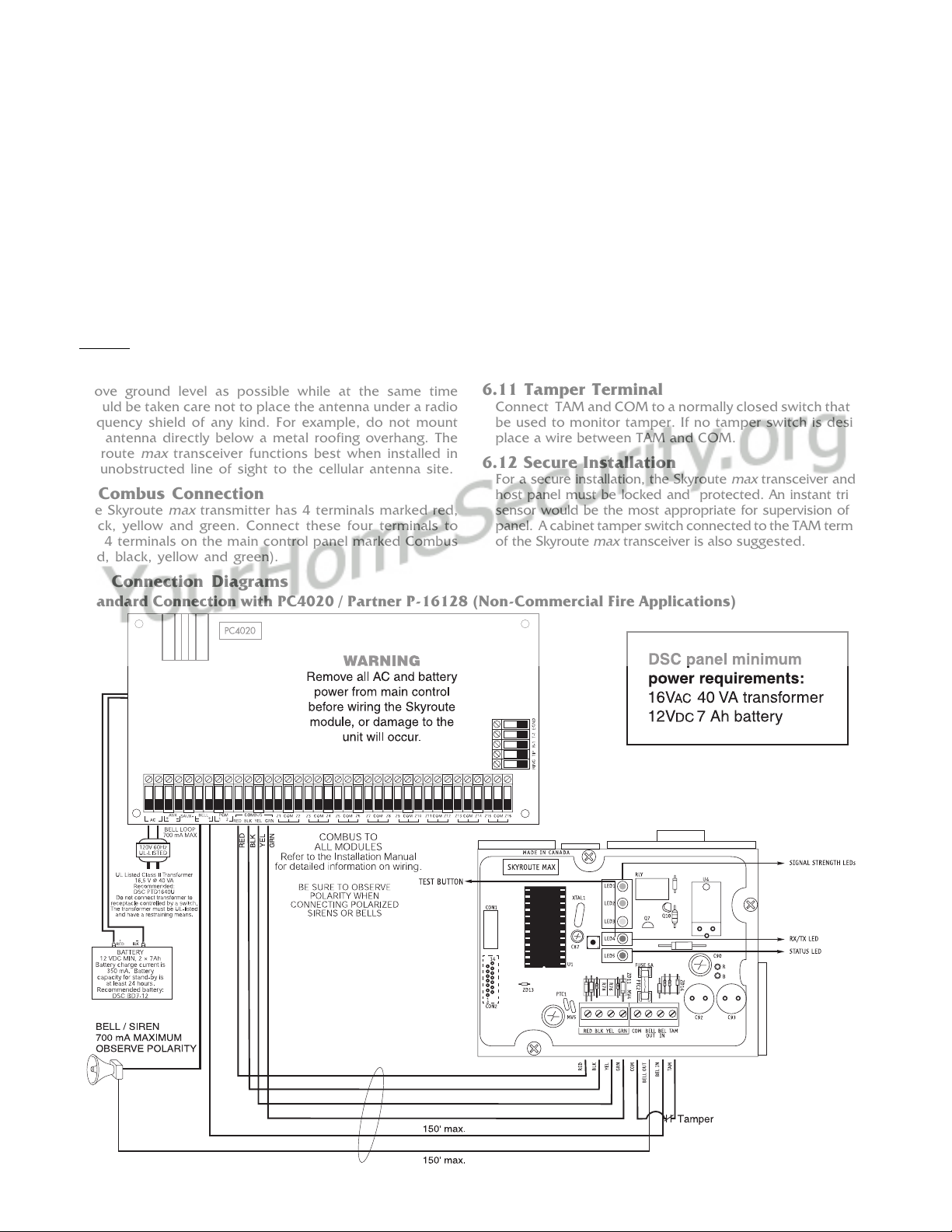
6.1 Location of the Skyroute
maxmax
maxmax
max
Unit
It is very important to determine the best location for maximum signal strength.
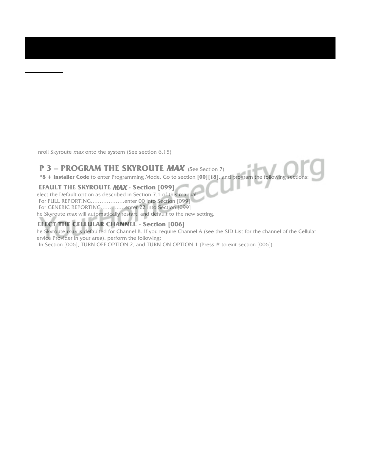
NOTE: In the US both Side A and Side B carriers may be used. Changes can be made in option [006] (see Section 8.1) of the
Skyroute programming.
Verify signal strength prior to installation!
6.2 Relocating the Skyroute
maxmax
maxmax
max
Transceiver
Since the Skyroute
max
transceiver is a Combus acces-
sory, it is possible to relocate the module up to 1000 feet
from the main control panel when the panel is not located
in a good cellemetry coverage area (a control panel
installed in a vault for example). When relocating the
module, follow theses rules:
• Maximum of 1000 feet from the main control. Combus
(Red, Black, Yellow, Green) from the panel to the
Skyroute
max
transceiver.
must be used for UL installations.
• The power supply (+ positive) is connected to the Skyroute
max
transceiver (BELL IN) terminal and the power supply
(–negative) to the Skyroute
max
transceiver (COM)
terminal.
• The cabinet must be installed in a secure location and
should have a tamper circuit connected to the Skyroute
max
(TAM and COM) terminals.
NOTE: FNOTE: F
NOTE: FNOTE: F
NOTE: For Side A Carriers the Skor Side A Carriers the Sk
or Side A Carriers the Skor Side A Carriers the Sk
or Side A Carriers the Skyroute Max will need toyroute Max will need to
yroute Max will need toyroute Max will need to
yroute Max will need to
be programmed first to look at the Side A. Refer tobe programmed first to look at the Side A. Refer to
be programmed first to look at the Side A. Refer tobe programmed first to look at the Side A. Refer to
be programmed first to look at the Side A. Refer to
Programming option 006.Programming option 006.
Programming option 006.Programming option 006.
Programming option 006.
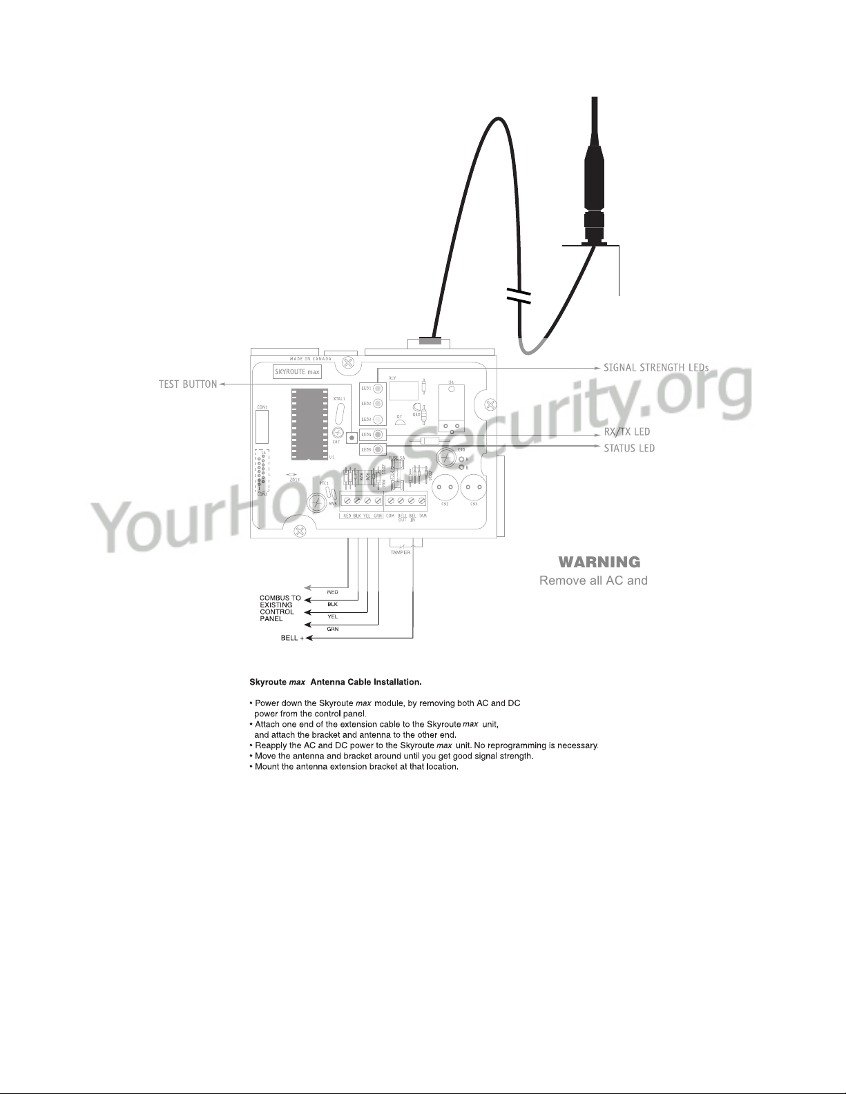
6.3 Relocating the Antenna
If a suitable location is not available for proper Cellemetry
coverage, obtain an Antenna Extension Bracket Kit from your
DSC/Sur-Gard supplier. Each kit contains an extension cable,
a mounting bracket, instructions, and all required hardware.
Three lengths of extension cable are available:
Extension Kit Length of cable
LAE-3 3 feet (0.91 m)
LAE-15 15 feet (4.57 m)
LAE-25 25 feet (7.62 m)
SKR-025 25 feet (7.62 m)
Only use the Extension Kits to extend the mounting range
of the antenna. Do not cut or splice the extension cable. The
maximum distance between the Skyroute
max
transceiver and
the antenna is 25 feet (7.62 m) as obtained by using the LAE-
25 or SKR-025 Extension Kit. Make sure the antenna is in a
physically secured location to avoid tampering.
Secure the TNC connector from the Extension Kit to the
mounting bracket, ensuring that the star washers make solid
electrical contact with the mounting bracket.
Remove the antenna from the Skyroute
max
module and
connect the extension cable to the TNC connector on the
module. Secure the antenna to the TNC connector mounted
on the Extension Kit mounting bracket. Locate the mounting
bracket and antenna away from possible sources of electrical
interference. Moving the antenna just a short distance will
likely be adequate. Temporarily secure the mounting bracket
in the new location and proceed with testing. If the test is
successful, permanently secure the mounting bracket and
antenna at the new location.
LED 1: Good signal strength
LED 2: Acceptable signal strength
LED 3: Poor signal strength
LED 4: One blink = Transmit TX
Two blinks = Receive RX
LED 5: Status (number of blinks)
1: Normal (activated)
2: Radio not powered-up
3: Failed self-test
4: No cell network
5: Fail to communicate
6: Ready to activate
8: Unit not enrolled with PC4020
Refer to section 10 Trouble-
shooting of this manual for more
information.
+-
12V 7Ah
Battery