DTM System ZSP Rival 432 User manual

I. Terms in use
II. General informations
III. Technical data
IV. Receiver installation
4
4
4
Monostable output mode – turn on for programmed time after pushing the button
Bistable output mode – turn mode to opposite (turn on or turn off) after pushing button
Momentary output mode – turn on as long as the button is being pushed
dynamically variable code Keeloq gives high class safety
superherterodine receiver, work frequency: 433.92 Mhz
reciver's memory containing 35 ZSP series remotes (NEO, TIP)
two separated NO relay outputs, working in mono-, bistable or momentary mode, max load for each output 1A/24V AC or
DC
turn on time in monostable mode: from 0,5 sec and from 1 sec to 127 sec, bistable mode remembers last state before
power down
simple remote registering without need of using receivers buttons
possibility to lock easy remote registering function
discretion with ascribing remote buttons to receivers outputs
terminal block to switch aerial's concentric cable
splash – proof case IP-53
receiver suppy from 12 V to 24 VAC/DC
max current constription:1005mA(with two channels on and 24 V supply)
dimension: enclosure [mm] heigh 118, width 55, depth 27,5
working temperatures from -20° C to +55° C
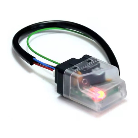
Strub aerial of 170 mm length is switched to aerial block in new receiver. To enhance radio range use outdoor aerial.
Outdoor aerial's concentric cable need to be switched to Y marked terminal block and ground marked terminal block.
4
4
4
4
4
4
4
4
4
4
4
4
4
4
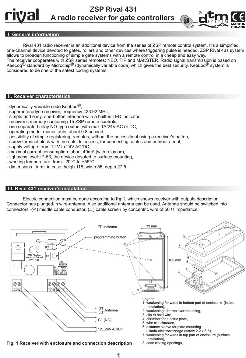
Rival 432 receiver is one of remote control and access control devices that build ZSP System. Basic application of
ZSP System is to work with controllers of gate, rollers, also lightning, alarm system (direct connection to alarm line or
switchboard) and direct contol of devices such as entryphone, intercome, etc. as well.
Thanks to new, full programed functions, Rival 432 receiver come up to clients expectations. New
and possibility of programming increase product values.
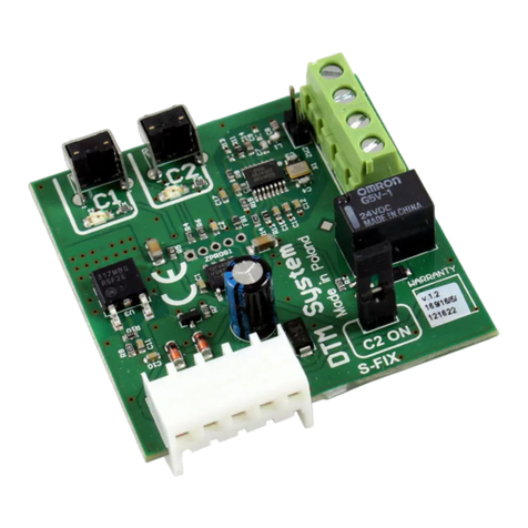
Rival 432 receiver contains of main board, the splash – proof case and aerial . Main board (fig.1) has
microprocessor control system of LED diodes and buttons, executive set on two relays, connectors of supply,connectors of
outside antenna and controled devices.
neighbourhood of the energetic devices and metal elements will short the range
radio interferance from other sources will short the range
avoid wet and concrete walls for mounting the receiver
remember to remove old used batteries from remotes
mount the receiver's as high as possible
use the good quality coaxial cable for making the outdoor aerial
simplify programming
interface more remote controls
Hints for making the radio range optimal:
-
-
-
-
-
-
1. Device description and installation
1
1
ZSP Rival 432
A radio receiver operating manual
2
1
3
4
MADE IN
POLAND

V. Programming
Rival 432 receiver programming has influence on working mode. Before programming fimilarize with fig.1 which
shows receivers board, localization of programming buttons, relay outputs C1 and C2, LED diodes. Lightining LED diodes
shows chosen channel and working mode. Next to LED diodes are short descriptions of signalized function. Receiver's
outputs are controled by remote control's programmed buttons
2
Fig. 1 Receiver board scheme
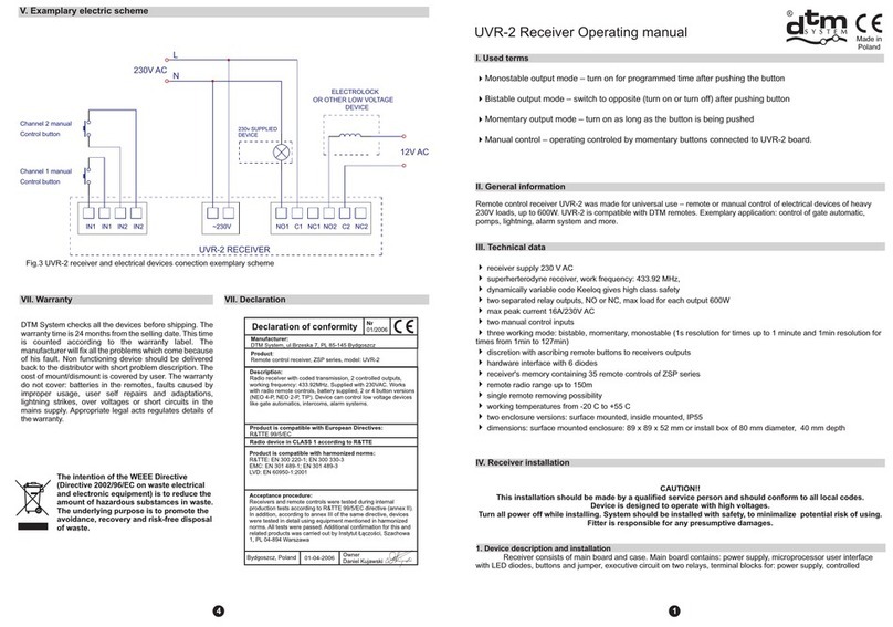
2. Exemplary electric scheme
Fig. 2 Exemplary electric scheme of Rival 432 receiver, gate controller and electrolock electric connection.
3
4
5
1
2
6
7
8
39 mm
102 mm
Turn on
signalling
Working mode
signallin
during
programming
momentary
monostable
bistable
Power
signalling
channel 1
channel 2
Programming
buttons:
shield
antenna
supply 12V...24V
AC/DC
channel 1
channel 2
output 1
output 2
electrolock
24V
gate controller
manual control output
STEP BY STEP
supply
24V AC/DC
Rival 432 receiver
Legend:
1. weakening for wires in bottom part of enclosure (inside
instalation),
2. weakenings for receiver mounting,
3. clip to hold wire,
4. chamber for electric plate,
5. wire clip clousure,
6. distance sleeve for plate mounting
układu elektronicznego (screw 2,2 x 6,5),
8. case closing openings,
7. weakening for wires in top part of enclosure (surface
instalation),

3
1) Registering remote control to receivers memory
2) Easy remote control registering
3) Simple remote control removing
4) Output (C1/C2) mode change to or .
5) Output (C1/C2) mode change to
bistable momentary
monostable
Registering remote control do receivers memory is adding particular button with simulataneously assing recivers
output.
It is possible to assing few of buttons to the same channel or to assing remote control button to both of channels.
To remove programmed button, it is necessary to delete remote control from receiver's memory, and assing buttons in right
confriguration (point 3).
Button registering
(C1/C2)
Remarks! C1/C2
Remarks!
Remarks!
Output's factory settings:
C1 output working mode –monostable (0,5s)
C2 output working mode –monostable (0,5s)
(C1/C2)
MOM BIST MONO
(C1/C2)
MONO
Remarks!
C1/C2 MONO
While pushing output button push choosen remote control's button. LED diode will light.
If pushing output button stops before pushing transmitter's button receiver will turn on output
programming mode. To exit push shortly other channel button.
It is possible to register new remote control without using receiver's buttons. New remote control must be in radio
range of receiver and previously registered remote control presence is necessary. Easy remote control registering is
unavailable if output is on momentary mode.
a) push and hold for 15 sec. any button of previously registered remote
b) within 3 sec. after releasing the previous button push and hold for 15 sec. any button of new remote control
c) new remote control is registered with same as previous remote configuration.
Failure in registering may be caused by radio interferences, low batteries or lock of easy remote registering
function.
To remove single remote control from receiver's memory push and hold simulataneously output buttons (C1 and
C2). All of LED diodes (except for green LED diode) will light. During lighting push any remote control's button that you want
to remove. Diodes will wane, remote will be removed from receiver's memory.
If you hold the receiver's C1 and C2 buttons for too long, receiver's memory will format.
For monostable mode check point 5.
To change mode of C1 or C2 output push and release chosen output button. Red LED diode will light .
Yellow LED diode shows actual output mode. Push output button several times to set working mode. Yellow LED diode with
sing for momentary mode, sing – bistable mode, sing – monostable mode (check point 5.) To approve
chosen mode push and hold output button (C1/C2). Red LED diode will light and wane. Working mode is registered.
To change output mode to monostable push and release button , red LED diode will light and yellow LED
diode which shows actual output mode will light. Push output button to set working mode on monostable, signalized by
yellow LED diode with sing. To approve push and hold edited output button (C1/C2). LED diode with MONO sing will
fade, than start to blink. Hold output button for wanted turn on time in seconds. Number of blinking set turn on time in seconds
(or minutes if after releasing in short time button is being pushed for second again.)
To set turn on time 0,5s release button before yellow diode with sing light.

The intention of the WEEE Directive
(Directive 2002/96/EC on waste electrical
and electronic equipment) is to reduce the
amount of hazardous substances in waste.
The underlying purpose is to promote the
avoidance, recovery and risk-free disposal
of waste.
VII. Warranty
DTM System checks all the devices before shipping. The
warranty time is 24 months from the selling date. This time
is counted according to the warranty label. The
manufacturer will fix all the problems which come because
of his fault. Non functioning device should be delivered
back to the distributor with short problem description. The
cost of mount/dismount is covered by user. The warranty
do not cover: batteries in the remotes, faults caused by
improper usage, user self repairs and adaptations,
lightning strikes, over voltages or short circuits in the
mains supply. Appropriate legal acts regulates details of
the warranty.
4
VIII. Declaration
2
1 2
VI. Remote TIP and NEO parameters
4
4
4
4
4
4
4
4
4
4
four (two) buttons that can control any channel or the group channels
signal transmission is based on Microchips® KeeLoq® dynamically variable code,
remote frequency 433,92 Mhz
up to 150m radio range NEO, 50m TIP
battery: L1028 23A 12V,
ERP
four (two) buttons that can control any channel or the group channels
signal transmission is based on Microchips® KeeLoq® dynamically variable code,
remote frequency 433,92 Mhz
TIP: 1 mW, NEO: 3 mW;
working temperature from 0°C to +55°C.
2
1
3
4
2
3
4
122
1 2
12
fig. 3. TIP and NEO remotes with buttons
7) Receiver's memory formating
To format receiver's memory push and hold simultaneously C1 and C2 buttons. All LED diodes (except green diode)
will blink. Release buttons when LED diodes stop blink (after about 15 seconds). Receiver's memory has been formated.
Remarks! Format is irreversible. All remotes will be removed from receiver's memory and return to factory settings
(C1 and C2 output in monostable mode turn on time 0,5s)
6) Lock / unlock easy remote control registering function
To secure device from unwanted remote registering (aspecial protected customers areas) it is recomended to lock
easy remote registering function.
To lock hold and release button , red LED diode will light , yellow LED diode which shows actual working
mode will light. Push and hold next button. After 4 seconds diode will light (means that easy remote control registering
function is active). Still hold the button. After another 4 seconds of holding button diode will light (means that easy remote
control registering function is locked). After releasing button, card will memorize settings and lock easy remote control
registering function.
Same procedure to unlock, just release button when diode light. By default – factory settings, easy remote control
function is unlock.
(C1/C2) (C1/C2)
C2
C1
C2
Declaration of conformity Nr
02/2009
Product is compatible with European Directives:
R&TTE 99/5/EC
Bydgoszcz, Poland 01-08-2009
www.dtm.pl
DTM System, ul. Brzeska 7, 85-145 Bydgoszcz
Table of contents
Other DTM System Receiver manuals

DTM System
DTM System cloud FLEX Manual

DTM System
DTM System PIKO User manual

DTM System
DTM System mini User instructions

DTM System
DTM System PERFECT SOS User manual

DTM System
DTM System SPC-433 User manual

DTM System
DTM System GALACTIC NANO 868 User manual

DTM System
DTM System S-FIX User manual

DTM System
DTM System MAX II User manual

DTM System
DTM System UVR-2 User manual

DTM System
DTM System NANO II Series User manual