DTM System PIKO User manual

PL
DE
EN
1-KANAŁOWY ODBIORNIK RADIOWY
Instrukcja obsługi
1-KANAL-FUNKEMPFÄNGER
Betriebsanleitung
1-CHANNEL RADIO RECEIVER
User’s manual
v.1.0
MUL
TI


ZDALNE WPISYWANIE PILOTÓW
BLOKADA ZDALNEGO WPISYWANIA
FUNKCJA GALACTIC
KONTROLA LICZBY PILOTÓW
tylko DTM433MHz tylko DTM433MHz
PAMIĘĆ
CZĘSTOTLIWOŚĆ
ZASILANIE
POBÓR PRĄDU
WYJŚCIE
OBCIĄŻENIE WYJŚCIA
TRYB PRACY
TEMPERATURA PRACY
STOPIEŃ SZCZELNOŚCI
WYMIARY
12…24V AC/DC ±10%
30mA
jedno odseparowane, przekaźnikowe typu NO
1A/24V AC/DC
monostabilny, z czasem podtrzymania 1s
-20°C /+55°C
41x30x19 mm
IP-20
15 pilotów
DTM433MHz
+ innych
producentów
150 pilotów
DTM433MHz 150 pilotów
DTM433MHz
+ innych
producentów
200 pilotów
DTM868MHz
15 pilotów
DTM433MHz
433MHz 868MHz
40mA
Rys. 1. Widok odbiornika
z opisem wyprowadzeń.
INFORMACJE OGÓLNE
Seria jednokanałowych odbiorników PIKO przeznaczona jest do współpracy ze sterownikami bram, rolet i innymi urządzeniami
automatyki, gdzie wymagane jest podanie impulsu sterującego. Pozwala w prosty i tani sposób poszerzyć funkcjonalność
instalacji o funkcję zdalnego sterowania.
DANE TECHNICZNE
1. Instalacja odbiornika
Odbiornik przeznaczony jest do zastosowań
wewnątrz puszek instalacyjnych, wewnątrz
budynków oraz wewnątrz obudów innych
urządzeń automatyki, przy zapewnieniu
odpowiednich warunków pracy, zgodnych z
parametrami urządzenia. Nie należy montować
odbiornika w miejscach narażonych na dużą
wilgoć oraz częste i nagłe zmiany temperatury.
Odbiornik posiada wiązkę kablową z czterema
przewodami (rys.1) do podłączenia zasilania
odbiornika - kolory czerwony i niebieski, oraz do
podłączenia sterowanego urządzenia - kolory
biały i czarny. Odbiornik fabrycznie wyposażony
jest w antenę drutową.
Obudowa posiada otwór na opaskę zaciskową
dla wygodnego montażu odbiornika.
Należy zwrócić uwagę na kolory
przewodów i podłączać zgodnie z
przeznaczeniem!
DOSTĘPNE FUNKCJE
PL
12-24V
CNO
BIAŁY
CZARNY
CZERWONY
NIEBIESKI
przycisk
programujący C1
dioda C1
wiązka
kablowa
antena
+~
_

2. Programowanie odbiornika
2.1. Wpisywanie pilota do pamięci odbiornika
W celu wpisania pilota do pamięci odbiornika należy trzymając jednocześnie wciśnięty przycisk odbiornika, nacisnąć wybrany
przycisk pilota, który ma zostać dopisany. Kontrolka zamruga sygnalizując dopisanie, należy zwolnić przycisk odbiornika.
Wybrany przycisk pilota będzie sterować kanałem wyjściowym odbiornika. W pamięci odbiornika mogą być wpisane dowolne
przyciski danego pilota.
Przytrzymanie przycisku odbiornika powyżej 15 sekund doprowadzi do usunięcia wszystkich pilotów z pamięci
odbiornika.
Próba wpisania kolejnego nadajnika do zapełnionej już pamięci odbiornika zakończy się niepowodzeniem.
2.2. Zdalne wpisywanie pilota do pamięci odbiornika
Funkcja zdalnego wpisywania pilota pozwala na dopisanie pilota bez konieczności fizycznego dostępu do odbiornika.
Warunkiem powodzenia jest konieczność znajdowania się w zasięgu radiowym odbiornika oraz posiadanie wcześniej wpisanego
pilota.
Aby zdalnie dopisać pilota należy w zasięgu odbiornika wcisnąć na 15 sekund przycisk już dopisanego pilota. Następnie w czasie
nie dłuższym niż 3 sekundy wcisnąć i przytrzymać przez 15 sekund przycisk pilota, który ma zostać dopisany. Nowy pilot zostanie
dopisany z identyczną konfiguracją przycisków jak pilot już dopisany użyty w tej procedurze.
Funkcja zdalnego wpisywania jest niedostępna w przypadku:
źzablokowania funkcji zdalnego wpisywania pilotów,
źużycia w procedurze pilotów dwóch różnych systemów,
źużycia w procedurze pilotów innych producentów.
Nieudane dopisanie pilota może być spowodowane:
źsłabą baterią któregoś z pilotów,
źzakłóceniami radiowymi, które mogły pojawić się w trakcie trwania procedury zdalnego wpisywania,
źzapełnieniem pamięci odbiornika.
2.3. Zablokowanie / odblokowanie zdalnego wpisywania pilotów (dostępne tylko dla wersji PIKO 868)
Chcąc zabezpieczyć urządzenie przed nieuprawnionymi próbami dopisania dodatkowego pilota (szczególnie istotne w
obszarach o chronionym dostępie użytkowników), należy zablokować funkcję zdalnego dopisywania pilotów.
W celu zablokowania/odblokowania funkcji zdalnego dopisywania pilotów należy:
źodłączyć zasilanie odbiornika;
źnacisnąć i przytrzymać przycisk C1;
źprzy wciśniętym przycisku włączyć zasilanie;
źdioda C1 zacznie cyklicznie zapalać się i gasnąć (co 5s). Jeśli przycisk zostanie puszczony w chwili, gdy:
dioda C1 świeci – blokada zostanie włączona,
dioda C1 jest zgaszona – blokada zostanie wyłączona.
1WCISNĄĆ NA 15s
PRZYCISK
"STAREGO" PILOTA
PO MAKSYMALNIE
3 SEKUNDACH
PILOT W ZASIĘGU
ODBIORNIKA
2WCISNĄĆ NA 15s
PRZYCISK
"NOWEGO" PILOTA
PILOT W ZASIĘGU
ODBIORNIKA
Rys. 3. Zdalne wpisywanie pilota.
2 31 PRZYCISNĄĆ PRZYCISK C1
DIODA ZACZNIE PULSOWAĆ PRZYCISNĄĆ WYBRANY
PRZYCISK PILOTA
C1 ZAMRUGA x3
- DOPISANIE UDANE
ZWOLNIĆ PRZYCISK C1
x3
Rys. 2. Wpisywanie pilota.
PL

2.4. Wprowadzenie kodu uwierzytelniającego funkcji GALACTIC do odbiornika (dostępne tylko dla wersji PIKO 868)
Do wprowadzenia kodu uwierzytelniającego do odbiornika, niezbędne jest posiadanie pilota z funkcją GALACTIC, z
ustawionym kodem uwierzytelniającym, wprowadzonym programatorem GPROG.
Aby wprowadzić kod uwierzytelniający do odbiornika należy przycisnąć dwa razy przycisk C1 odbiornika. Dioda zacznie mrugać
przez 8 sekund. W tym czasie nalezy nacisnąć i przytrzymać przez 5 sekund dwa dowolne przyciski pilota. Od tego momentu w
odbiorniku ustawiony jest kod uwierzytelniający i można dopisywać piloty z użyciem funkcji GALACTIC (pkt. 2.6.).
Jeżeli w ciągu 8 sekund od podwójnego wciśnięcia kod nie zostanie wprowadzony lub wprowadzenie kodu nie powiedzie się,
dioda C1 nie zamruga ale od razu zaświeci się.
Częstotliwość mrugania diody po dwukrotnym przyciśnięciu przycisku C1 odbiornika informuje, czy kod uwierzytelniający jest
ustawiony.
Bardzo szybkie mruganie diody (10 mrugnięć na sekundę) informuje o braku kodu Galactic w odbiorniku.
Wolne mruganie (1 mrugnięcie na sekundę) informuje o ustawionym kodzie uwierzytelniającym funkcji Galactic.
2.5. Usunięcie kodu uwierzytelniającego funkcji GALACTIC z odbiornika (dostępne tylko dla wersji PIKO 868)
Do usunięcia kodu uwierzytelniającego za pomocą pilota, konieczne jest posiadanie pilota z funkcją GALACTIC, którym
kod został wprowadzony.
Należy nacisnąć dwukrotnie przycisk C1 odbiornika. Dioda zacznie wolno mrugać przez 8 sekund. W tym czasie należy przycisnąć
dwa dowolne przyciski pilota, którym kod został wprowadzony.
Kod uwierzytelniający funkcji GALACTIC zostaje usunięty po sformatowaniu pamięci odbiornika (pkt.2.8.).
2.6. Wpisywanie pilota z funkcją GALACTIC (dostępne tylko dla wersji PIKO 868)
Warunkiem powodzenia wpisywania pilota jest zgodność kodów uwierzytelniających ustawionych w odbiorniku i
pilocie z funkcją GALACTIC.
W celu dopisania pilota należy w zasięgu odbiornika nacisnąć i przytrzymać przez 5 sekund dwa dowolne przyciski pilota.
Dopisanie pilota sygnalizuje trzykrotne mrugnięcie diody C1 odbiornika. W celu aktywowania pilota w pamięci odbiornika należy
wcisnąć dowolny przycisk pilota.
Nieudane dopisanie pilota może być spowodowane:
źniezgodnością kodów uwierzytelniających odbiornika i nadajnika,
źsłabą baterią pilota,
źzakłóceniami radiowymi, które mogły pojawić się w trakcie trwania procedury zdalnego wpisywania,
źzapełnieniem pamięci odbiornika
2 3 41 PRZYCISNĄĆ DWUKROTNIE
PRZYCISK C1 DIODA ZACZNIE
MRUGAĆ PRZEZ 8 SEKUND
WCISNĄĆ DWA PRZYCISKI
PILOTA Z KODEM GALACTIC
NA 5 SEKUND
C1 ZAMRUGA x3
- WPROWADZENIE
KODU UDANE
x2 x3
PILOT Z KODEM
GALACTIC
2 31 W ZASIĘGU RADIOWYM
ODBIORNIKA
WCISNĄĆ NA 5 SEKUND
DWA PRZYCISKI PILOTA
Z KODEM GALACTIC
C1 ZAMRUGA x3
- WPROWADZENIE
PILOTA UDANE
x3
5s PILOT Z KODEM
GALACTIC
Rys. 4. Wprowadzenie kodu uwierzytelniającego funkcji Galactic do odbiornika.
Rys. 5. Wpisywanie pilota z funkcją Galactic do odbiornika.
PL

2.7. Usuwanie pojedynczego pilota z pamięci odbiornika
W celu usunięcia pojedynczego pilota z pamięci odbiornika należy trzymając wciśnięty przycisk odbiornika, nacisnąć aktywny
przycisk pilota.
Przytrzymanie przycisku odbiornika powyżej 15 sekund doprowadzi do usunięcia wszystkich pilotów z pamięci odbiornika.
2.8. Formatowanie pamięci
W celu sformatowania pamięci odbiornika, należy nacisnąć i przytrzymać przez 15 sekund przycisk odbiornika. Przycisk należy
zwolnić dopiero gdy kontrolka zgaśnie.
Formatowanie pamięci:
źusuwa wszystkie piloty z odbiornika,
źwyłącza blokadę zdalnego wpisywania pilotów,
źusuwa kod uwierzytelniający funkcji Galactic z odbiornika.
2.9. Kontrola liczby wpisanych pilotów
W celu sprawdzenia liczby pilotów wpisanych do pamięci odbiornika, należy po operacji wpisania lub usunięcia pilota,
przytrzymać wciśnięty przycisk w odbiorniku jeszcze przez ok. 5 sekund. Kontrolka zacznie pulsować wskazując liczbę
zaprogramowanych pilotów. Kolejno pokazywana jest liczba dziesiątek (długi impuls) następnie cyfra jedności (od 0 do 9 krótkich
impulsów). W wersji PIKO kontrolka pulsuje wskazując liczbę zaprogramowanych pilotów.
Rys. 8. Przykład impulsów pokazujących liczbę wpisanych pilotów - 46 sztuk.
liczba dziesiątek - 4x10 liczba jednostek - 6
1 2 PO OKOŁO 15 SEKUNDACH
DIODA ZGAŚNIE - KONIEC
PROCESU FORMATOWANIA
> 15s
Rys. 7. Formatowanie pamięci.
PRZYCISNĄĆ PRZYCISK C1
DIODA ZACZNIE PULSOWAĆ
2 31 PRZYCISNĄĆ PRZYCISK C1
DIODA ZACZNIE PULSOWAĆ PRZYCISNĄĆ
PRZYCISK PILOTA
C1 ZGAŚNIE
- USUNIĘCIE UDANE
ZWOLNIĆ PRZYCISK C1
Rys. 6. Usunięcie pilota.
PL

12…24V AC/DC ±10%
30mA
1A/24V AC/DC
-20°C /+55°C
41x30x19 mm
IP-20
433MHz 868MHz
40mA
15 Handsender
DTM433MHz
+ anderer
Hersteller
150 Handsender
DTM433MHz 150 Handsender
DTM433MHz
+ anderer
Hersteller
200 Handsender
DTM868MHz
15 Handsender
DTM433MHz
SPEICHER
FREQUENZ
SPANNUNGSVERSORGUNG
STROMAUFNAHME
AUSGANG
AUSGANGSLAST
BETRIEBSMODUS
TEMPERATUR
SCHUTZART
ABMESSUNGEN
Ein separater NO-Relais-Ausgang
Monostabil, mit Stand-by 1s
nur DTM433MHz nur DTM433MHz
FERNGESTEUERTE SPEICHERUNG
DES HANDSENDERS
SPERRE DER FERNGESTEUERTEN SPEICHERUNG
DES HANDSENDERS
FUNKTION GALACTIC
ÜBERPRÜFUNG DER ANZAHL
DER GESPEICHERTEN HANDSENDER
ALLGEMEINE INFORMATIONEN
Die Serie der einkanaligen PIKO-Empfänger ist für die Zusammenarbeit mit Torsteuerungen, Rollläden und anderen
Automatisierungsgeräten konzipiert, bei denen ein Steuerimpuls erforderlich ist. Es ermöglicht Ihnen, die Funktionalität der
Anlage einfach und kostengünstig mit der Fernbedienungsfunktion zu erweitern.
TECHNISCHE DATEN
1. Installation des Empfängers
De r Emp fän ge r ist f ür d en Ei nsa tz i n
Einbaudosen, in Gebäuden und in Gehäusen
anderer Automatisierungsgeräte konzipiert und
g e w äh r l e i s tet g lei c h z eit i g ko r r e k te
Arbeitsbedingungen, die mit den Parametern
des Gerätes übereinstimmen. Installieren Sie
den Empfänger nicht in Bereichen, die hoher
Luftfeuchtigkeit und häufigen und plötzlichen
Temperaturschwankungen ausgesetzt sind.
Der Empfänger verfügt über einen Kabelbaum
mit vier Adern (Abb. 1) zum Anschluss der
Stromversorgung des Empfängers - rot und blau
- un d zu m An sch lu ss d er ges te uer te n
Vorrichtung - weiß und schwarz. Der Empfänger
ist werksei tig mit ein er Drahtant enn e
ausgestattet.
Das Gehäuse verfügt über eine Bohrung für
einen Kabelbinder zur einfachen Installation des
Empfängers.
Achten Sie auf die Farben der Kabel
un d s ch ließen Si e diese w ie
vorgesehen an!
VERFÜGBARKEIT DER FUNKTIONALITÄTEN
12-24V
CNO
WEISS
SCHWARZ
ROT
BLAU
C1 Programmiertaste
C1 LED
Kabelbaum
Antenne
+~
_
Abb. 1. Ansicht
des Funkempfängers inkl.
Beschr. der Eingaben.
DE

2. Programmieren des Funkempfängers
2.1. Speichern des Handsenders im Funkempfänger
Zum Speichern des Handsenders im Funkempfänger ist die Taste des Empfängers gedrückt zu halten, dabei ist gleichzeitig die
gewählte Taste des zu speichernden Handsenders zu drücken. Nachdem die blinkende Diode ein erfolgreiches Speichern
signalisiert, ist die Taste des Funkempfängers loszulassen. Die gewählte Handsendertaste steuert mit dem Ausgangskanal des
Funkempfängers. Im Speicher des Funkempfängers können beliebige Tasten des jeweiligen Handsenders eingegeben werden.
Indem die Taste des Funkempfängers länger als 15 Sekunden gedrückt gehalten wird, werden alle Handsender aus dem
Speicher des Funkempfängers gelöscht. Der Versuch, einen weiteren Handsender im bereits vollen Speicher des
Funkempfängers hinzufügen, misslingt.
2.2. Ferngesteuertes Speichern des Handsenders im Funkempfänger
Die Funktion der ferngesteuerten Speicherung des Handsenders macht es möglich, den Handsender ohne physischen Zugang
zum Funkempfänger hinzufügen.
Eine Voraussetzung für die erfolgreiche Speicherung ist es, sich in der Funkreichweite des Funkempfängers aufzuhalten, sowie
über einen vorher gespeicherten Handsender zu verfügen.
Um einen Handsender ferngesteuert hinzufügen, halten Sie in der Reichweite des Funkempfängers die Taste des bereits
zugefügten Handsenders 15 Sekunden lang gedrückt. Anschließend drücken Sie nach max. 3 Sekunden und halten 15 Sekunden
lang die Taste des zu speichernden Handsenders gedrückt. Der neue Handsender wird mit einer identischen Tastenkonfiguration
wie bei dem bereits gespeicherten, bei diesem Verfahren eingesetzten Handsender, gespeichert.
Die Funktion für ferngesteuertes Speichern ist nicht zugänglich, wenn:
źdas ferngesteuerte Einlernen von Handsendern blockiert ist,
źbei dem Verfahren die Handsender mit verschiedener Frequenz verwendet werden,
źbei dem Verfahren die Handsender anderer Hersteller verwendet werden.
Mögliche Ursachen eines erfolglosen Hinzufügens des Handsenders:
źBatterie eines der Handsender ist schwach,
źBeim Speicherverfahren treten die Funkstörungen auf,
źSpeicher des Funkempfängers ist voll.
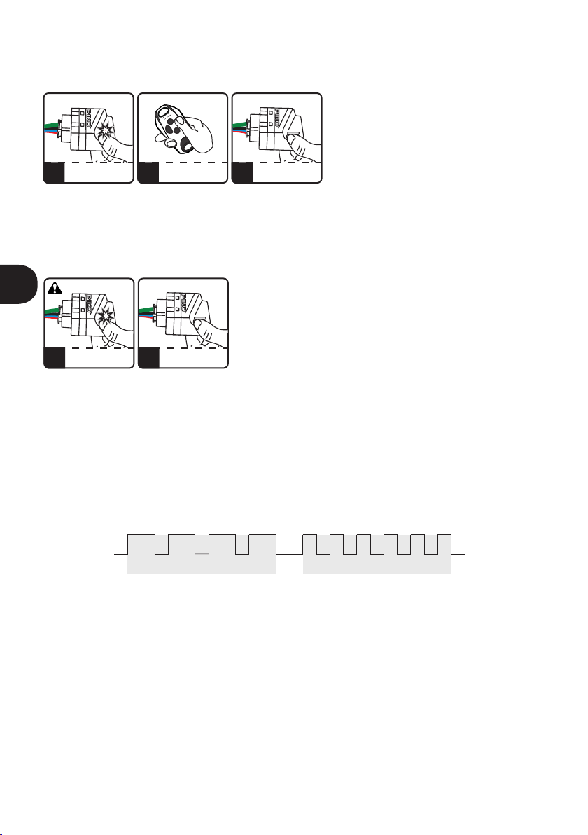
2.3. Blockieren/Freigabe ferngesteuerter Speicherfunktion (Zugänglich nur für die PIKO 868--Version)
Zum Schutz des Gerätes vor unbefugtem Einlernen eines zusätzlichen Handsenders (insbesondere in zugriffsgeschützten
Bereichen), ist die Funktion für ferngesteuertes Speichern der Handsender zu blockieren. Zu diesem Zweck muss man:
źEmpfängerversorgung abschalten;
źTaste C1 gedrückt halten;
źBei gedrückter Taste die Versorgung wieder einschalten;
źDie C1-Diode fängt an abwechselnd aufzuleuchten und zu erlöschen (alle 5 Sek.). Wird die Taste losgelassen, wenn:
die C1-LED leuchtet – wird die Blockade aktiviert;
die C1-LED erlischt – wird die Blockade deaktiviert.
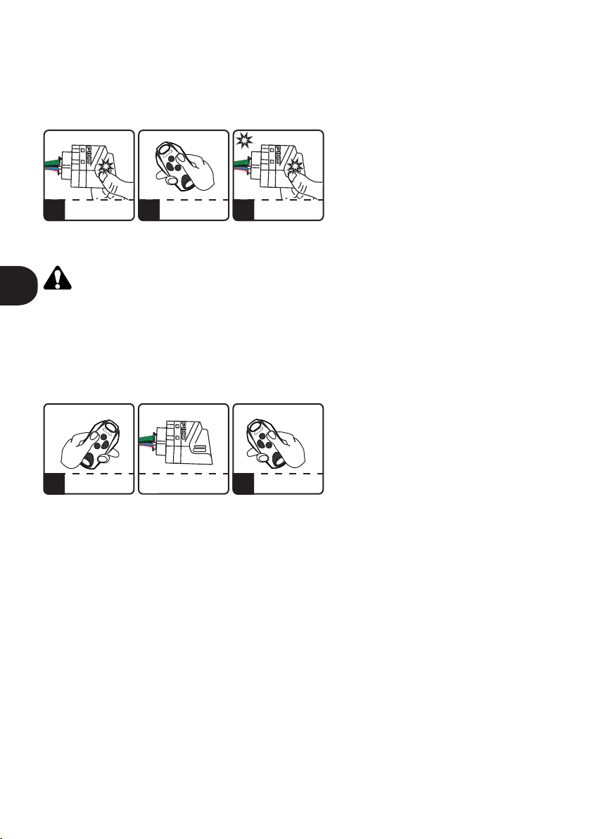
1EINE BELIEBIGE TASTE DES
‚ALTEN’ HANDSENDERS 15 SEK.
LANG GEDRÜCKT HALTEN
DIE PAUSENZEIT DAZWISCHEN
3 SEKUNDEN
DER SENDER IM
FUNKBEREICH
2EINE BELIEBIGE TASTE DES
‚NEUEN’ HANDSENDERS 15 SEK.
LANG GEDRÜCKT HALTEN
DER SENDER IM
FUNKBEREICH
Abb. 3. Ferngesteuertes Speichern des Handsenders.
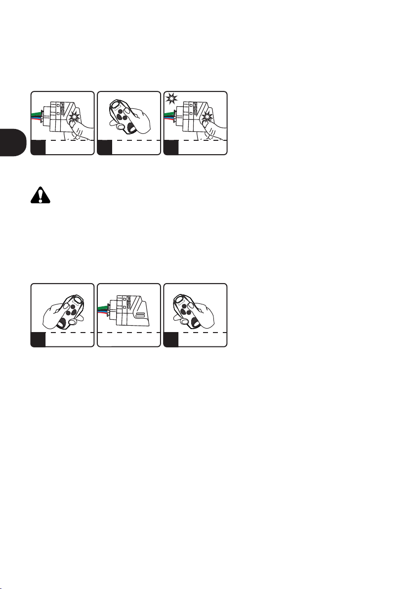
2 31 DIE C1-TASTE DRÜCKEN
DIE DIODE BLINKT
DIE AUSGEWAHLTE
HANDSENDERTASTE
GLEICHZEITIG DRÜCKEN
DIE DIODE BLINKT DREI MAL
SPEICHERN ERFOLGREICH
DIE C-TASTE LOSLASSEN
x3
Abb. 2. Speichern des Handsenders.
PL
DE

2.4. Eingabe des Bestätigungscodes zum Funkempfänger im GALACTIC-System (Zugänglich nur für die PIKO 868-Version)
Zur Eingabe des Bestätigungscodes zum Funkempfänger braucht man den Handsender mit Galacticfunktion, der mit
dem Bestätigungscode mithilfe des GPROG-Gerätes, programmiert wurde.
Um den Bestätigungscode zum Funkempfänger einzugeben, muss man zweimal die C1- Taste am Empfänger drücken. Dann
blinkt die Diode 8 Sekunden lang. Innerhalb von diesen 8 Sekunden soll man zwei beliebige Tasten des programmierten
Handsenders 5 Sekunden lang gedrückt halten. Ab jetzt ist beim Empfänger der Bestätigungscode eingestellt, was die
Speicherung von Handsendern mit Galacticfunktion ermöglicht. (sehe Pkt.2.6.). Falls innerhalb von 8 Sekunden, nachdem die
C1-Taste zweimal gedrückt worden ist, wird der Bestätigungscode nicht eingeführt (die Einführung misslingt), wird die C1-Diode
nicht blinken, sondern fängt an sofort andauernd zu leuchten.
Die Blinkfrequenz der C1-Diode informiert darüber, ob der Bestätigungscode eingestellt ist. Sehr schnelles Blinken der C1-Diode
(10mal/Sek.) weist auf fehlenden Bestätigungscode im Funkempfänger hin. Langsames Blinken der C1-Diode (1mal/Sek.) weist
hin, dass der Bestätigungscode im Funkempfänger eingestellt worden ist.
2.5. Löschen des Bestätigungscodes aus dem Funkempfänger im GALACTIC-System (Zugänglich nur für die PIKO 868-
Version)
Zum Löschen des Bestätigungscodes aus dem Funkempfänger braucht man denselben Handsender, mithilfe dessen
der Bestätigungscode eingestellt wurde.
Um den Bestätigungscode aus dem Funkempfänger zu löschen, muss man die C1-Taste am Funkempfänger zweimal drücken.
Dann blinkt die Diode langsam 8 Sekunden lang. Innerhalb von diesen 8 Sekunden soll man zwei beliebige Tasten des
Handsenders gedrückt halten.
Die Formatierung des Empfänger-Speichers verursacht das Löschen des Bestätigungscodes aus dem Empfänger. (sehe Pkt.2.8.).
2.6. Die Speicherung des Handsenders mit der Galactic-Funktion (Zugänglich nur für die PIKO 868-Version)
Eine Voraussetzung für die erfolgreiche Speicherung des Handsenders ist es, dass der Bestätigungscode sowohl im
Funkempfänger, als auch im Handsender mit der Galactic-Funktion, übereinstimmt.
Um einen Handsender hinzufügen, halten Sie in der Funkreichweite des Funkempfängers zwei beliebige Tasten des Handsenders
5 Sekunden lang gedrückt.
Mögliche Ursachen der erfolglosen Speicherung des Handsenders::
źder Bestätigungscode des Funkempfängers und des Handsenders stimmen nicht überein
źBatterie des Handsenders ist schwach,
źbeim Speicherverfahren treten die Funkstörungen auf,
źder Speicher des Funkempfängers ist voll.
2 3 41 DIE C1-TASTE ZWEIMAL
DRÜCKEN DIE C1-DIODE BLINKT
8 SEK. LANG
ZWEI HANDSENDERTASTEN
5 SEK. LANG GEDRÜCKT
HALTEN
C1-DIODE BLINKT DREIMAL
EINGABE DES GALACTIC
-CODES ERFOLGREICH
x2 x3
HANDSENDER MIT
GALACTIC-CODE
2 31 DER HANDSENDER
IM EMPFÄNGERBEREICH
ZWEI HANDSENDERTASTEN
5 SEK. LANG GEDRÜCKT
HALTEN
DIE C1-DIODE BLINKT
DREIMAL SPEICHERUNG
ERFOLGREICH
x3
5s HANDSENDER MIT
GALACTIC-CODE
Abb. 4. Eingabe des Bestätigungscodes zum Funkempfänger.
Abb. 5. Speicherung des Handsenders mit der Funktion Galactic.
PL
DE

2.7. Löschen des einzelnen Handsenders vom Empfängerspeicher
Halten Sie den Empfängerknopf gedrückt und drücken Sie gleichzeitig die aktive Handsendertaste. Die Löschung des
Handsenders wird durch Erlöschen der Diode bestätigt.
Wird die Empfängertaste länger als 15 Sek. gedrückt gehalten, werden alle eingelesenen Handsender aus dem Speicher entfernt.
2.8. Speicherformatierung
Um alle Handsender zu löschen, halten Sie die Empfängertaste 15 Sek. lang gedrückt. Die Taste kann erst dann losgelassen
werden, wenn die Diode erlöscht. Der Speicher ist dann leer.
Mit der Formatierung des Speichers:
źwerden alle Handsender vom Funkempfänger gelöscht,
źwird die Sperre der ferngesteuerten Speicherung der Handsender aufgehoben,
źder Bestätigungscode wird aus dem Empfänger gelöscht.
2.9. Überprüfungsfunktion der Anzahl von eingelernten Handsendern
Um die Anzahl von eingelernten Handsendern zu überprüfen, soll man beim Einlernen oder beim Löschen des Handsenders die
Taste am Funkempfänger noch 5 Sekunden länger gedrückt halten. Die Diode beginnt zu blinken, wobei die Blinkanzahl der
Anzahl von eingelernten Handsendern entspricht. Langes Blinken bezieht sich auf Zehnerstelle (0-20) und kurzes Blinken bezieht
sich auf Einerstelle (0-9). In der PIKO-Version die pulsierte Diode zeigt die Anzahl der programmierten Handsender.
Abb. 8. Beispiel der Signalisierung von 46 eingelernten Handsendern.
Zehnerstelle - 4x10 Einerstelle - 6
1 2 NACH CA. 15 SEK. DIE DIODE
ERLÖSCHT DIE FORMATIERUNG
ERFOLGREICH
> 15s
Abb. 7. Speicherformatierung.
DIE C1-TASTE 15 SEK. LANG
GEDRÜCKT HALTEN
DIE DIODE BLINKT
2 31 DIE C1-TASTE GEDRÜCKT
HALTEN DIE DIODE BLINKT
DIE AKTIVE
HANDSENDERTASTE
DRÜCKEN
DIE C1-DIODE ERLÖSCHT
LÖSCHEN ERFOLGREICH
DIE C1-TASTE LOSLASSEN
Abb. 6. Löschen einzelner Handsenders.
PL
DE

GENERAL INFORMATION
The series of 1-channel PIKO receivers are designed for cooperation with gate controllers, roller shutters and other automation
devices, where the remote control is required. It allows to easily extend the functionality of the installation with the remote
control function.
TECHNICAL DATA
1. Installing the receiver
The receiver is intended for use inside
installation boxes, inside buildings and inside
enclosures of other automation devices, while
ensuring appropriate operating conditions,
consistent with the device parameters. Do not
install the receiver in places subject to high
humidity or frequent and sudden changes in
temperature.
Othe receiver has a cable harness with four wires
(fig.1) for connecting the receiver's power supply
- red and blue, and for connecting a controlled
device - white and black. The receiver is factory
equipped with a wire antenna.
The housing has a hole for a clamp for
convenient mounting of the receiver.
Pay attention to the colors of the
wire s and c onne c t t h e m a s
intended!
AVAILABLE FUNCTIONS
12-24V
CNO
WHITE
BLACK
RED
BLUE
C1 programming
button
C1 LED
cable
harness
antenna
+~
_
12…24V AC/DC ±10%
30mA
1A/24V AC/DC
-20°C /+55°C
41x30x19 mm
IP-20
433MHz 868MHz
40mA
15 remotes
DTM433MHz
+ other
producers
150 remotes
DTM433MHz 150 remotes
DTM433MHz
+ other
producers
200 remotes
DTM868MHz
15 remotes
DTM433MHz
MEMORY
FREQUENCY
POWER SUPPLY
POWER CONSUMPTION
OUTPUT
OUTPUT LOAD
OPERATION MODE
TEMPERATURE
INGRESS PROTECTION
DIMENSIONS
one, separated NO type
monostable, turn-on time 1s
EASY REMOTE ADDING
EASY REMOTE ADDING LOCK
GALACTIC FUNCTION
VERIFYING NUMBER OF REMOTES
only DTM433MHz only DTM433MHz
Fig. 1. View of the receiver
with pin description.
EN

2. Receiver programming
2.1. Adding the remote control into the receiver's memory
In order to add the remote control into the receiver's memory, press the receiver button and press the selected remote control
button. The LED blinks indicating the add, release the receiver button. The selected button of the remote control will control the
output channel of the receiver. Any button of the remote control can be added in the receiver's memory.
Holding down the receiver button for more than 15 seconds will remove all the remote controls from the receiver.
Attempting to add another remote control into the already-filled memory of the receiver will fail.
2.2. Easy remote control adding
Easy remote control adding function allows adding a remote control without access to receiver.
Previously added remote is needed.
For easy remote control adding press and hold for 15 seconds, already added remote control button in receiver radio range. In no
more than 3 seconds press and hold new remote control button for 15 seconds. New remote is added with the same button
configuration as in previously added remote control used in the procedure.
Easy remote control adding function is disabled if:
źthe function is locked,
źuse in the procedure remote controls of two different frequencies,
źuse in the procedure remote controls of other manufacturers.
Failure in remote control adding may be caused by:
źa low battery of any of remote controls,
źradio interference that may have occurred during the procedure,
źa full memory of the receiver.
2.3. Locking/unlocking easy remote control adding function (available only for PIKO 868)
To protect receiver against unauthorized attempts of adding a remote control (important in access protected user zones) easy
remote control adding function must be locked.
To lock/unlock easy remote control adding function:
źturn off receiver power supply,
źpress and hold C1 button
źturn on receiver power supply
źC1 LED will alternately light on and light off every 5 seconds. If the C1 button will be released when:
C1 light on - easy remote control adding function is locked;
C1 light off - easy remote control adding function is unlocked.
1PRESS AND HOLD
FOR 15 SECONDS
„OLD” REMOTE BUTTON AFTER MAX 3 SECONDS
REMOTE IN RECEIVER
RADIO RANGE
2PRESS AND HOLD
FOR 15 SECONDS
„NEW” REMOTE CONTROL
REMOTE IN RECEIVER
RADIO RANGE
Fig. 3. Easy remote control adding.
2 31 PRESS C1
LED BLINKS PRESS REMOTE CONTROL
BUTTON
C1 BLINKS x3
ADDING SUCCESSFUL
RELEASE C1 BUTTON
x3
Fig. 2. Adding a remote control.
PL
EN

2.4. Entering Galactic authentication code to receiver (available only for PIKO 868)
To enter an authentication code to receiver it is necessary to have remote with programmed authentication code by
GPROG programmer.
To enter an authentication code to receiver press the C1 button twice. LED starts blinking for 8 seconds. During this time press and
hold for 5 seconds two buttons of the remote. Successful entering of the code indicates the C1 LED that blinks three times. From
that moment the receiver has authentication code set and programmable remotes with Galactic function can be added.
If within 8 seconds after pressing C1 button twice, the code is not entered, or code entering fails, the LED will not blink three times
but immediately light up.
The frequency of the LED blinking after double pressing the C1 button of the receiver informs whether the authentication code is
set.
A very fast blinking (10 blinks per second) informs that the Galactic code is not set in the receiver.
A slow blink (1 blink per second) informs that the Galactic authentication code is set in the receiver.
2.5. Removing Galactic authentication code from the receiver (available only for PIKO 868)
To remove the authentication code it is necessary to have a remote which the code has been entered.
To remove the authentication code press C1 button twice. LED goes out for 8 seconds. During this time press and hold two
buttons of the remote. Successful removing of the code indicates the C1 LEDs blink three times. If within 8 seconds after pressing
C1 button twice, the code is not removed, or code removing fails, the LED will not blink three times but immediately light up.
Memory format removes the authentication code from receiver.
2.6. Adding a remote with the use of Galactic function (available only for PIKO 868)
To add remote with the use of Galactic function, authentication codes of the receiver and remote must be compatible.
To add the remote press and hold for 5 seconds two buttons of the remote, in receiver radio range. Successful adding is indicated
by C1 LED three blinks. To activate the remote at the receiver's memory, press any button on the remote.
Failure in registering may be caused by:
źincompatibility of authentication codes in receiver and remote,
źlow battery of the remote,
źradio interference during the procedure,
źfull memory of the receiver.
2 3 41 PRESS TWICE
C1 BUTTON C1 STARTS BLINKING
FOR 8 SECONDS
PRESS AND HOLD FOR 5s
TWO BUTTONS
OF THE REMOTE CONTROL
C1 BLINKS x3
- CODE ENTERING
SUCCESSFUL
x2 x3
REMOTE WITH GALACTIC
CODE
2 31 IN RECEIVER RADIO
RANGE
PRESS FOR 5 SECONDS
TWO BUTTONS
OF THE REMOTE
C1 BLINKS x3
REMOTE ADDING
SUCCESSFUL
x3
5s REMOTE WITH
GALACTIC
Fig. 4. Entering Galactic authentication code to receiver.
Fig. 5. Adding a remote with Galactic function.
PL
EN

2.7. Deleting a single remote control from the receiver's memory
To remove a single remote from the receiver's memory, hold down the receiver button and press the active remote control
button.
Holding down the receiver button for more than 15 seconds will remove all the remote controls from the receiver.
2.8. Memory format
To format the receiver's memory, press and hold the receiver button for 15 seconds. Release the button only when the light goes
out.
Memory format:
źremovers all remote controls from the receiver,
źdisables the easy remote adding lock,
źdeletes the Galactic authentication code from the receiver.
2.9. Verifying number of added remotes
To verify number of registered remotes, prior registering or removing remote is required.
After registering or removing remote, hold receiver button for 5 more seconds. LED will blink showing number of registered
remotes. First number of tens (from 0 to 20 long pulses), then number of units (from 0 to 9 short pulses). In the PIKO version, the
indicator lamp flashes indicating the number of programmed remote controls.
Fig. 8. Pulses example, showing 46 registered remotes.
number of tens - 4x10 number of units - 6
1 2 AFTER 15 SECONDS
C1 LED GOES OUT
- FORMAT SUCCESSFUL
> 15s
Fig. 7. Memory format.
PRESS AND HOLD C1
LED PULSES
2 31 PRESS AND HOLD C1
LED PULSES PRESS REMOTE
ACTIVE BUTTON C1 LED GOES OUT
- DELETING SUCCESSFUL
Fig. 6. Deleting a single remote control.
PL
EN

DISPOSAL
Electrical or electronic devices cannot be
removed with everyday waste. The correct
recycling of devices gives the possibility of
keeping natural resources of the Earth for a
longer time and prevents the degradation
of natural environment.
WARRANTY
DTM System provides operational and
ready to use devices and gives 24 months
warranty from the selling date to the end
customer. This time is counted according
to the producer warranty labels or serial
numbers placed on every product. DTM
System obliges itself to repair the device
for free if during the warranty period there
are problems which come because of its
fault. Broken device should be supplied on
customer’s expense to the place of
purchase and enclose clear and brief
description of the breakage. The cost of
mount/dismount is covered by the user.
The warranty does not cover any faults
caused by improper usage, user self
repairs, regulations and adaptations,
lightning strikes, voltages or short circuits
in the electrical grid. Appropriate legal acts
regulate details of the warranty.
ENTSORGUNG
Entsorgung der Elektrogeräte bzw.
Elektronik darf nicht in Rahmen der
Ha us ha lt sa bf äl le e rfo lg en . E in e
sachgerechte Entsorgung des Gerätes
m a c h t e s m ö g l i c h , n a t ü r l i c h e
Erdressourcen länger aufrecht zu erhalten
s o w i e d e r U m w e l t z e r s t ö r u n g
vorzubeugen.
GARANTIEBEDINGUNGEN
Der Hersteller DTM System übergibt
funktionsfähige und nutzungsbereite
Geräte. Der Hersteller erteilt eine Garantie
von 24 Monaten nach Einkaufsdatum vom
Endkunden gerechnet. Die Garantiezeit
wird auf Basis von Garantieblomben des
Herstellers, die an jedem Erzeugnis
angebracht werden, festgelegt. Der
Hersteller verpflichtet sich dazu, das Gerät
kostenfrei zu reparieren, wenn in der
Garantiezeit Mängel durch Verschulden
des H erst el lers a uftr eten . N icht
funktionsfähiges Gerät ist auf eigene
Rechnung an die Einkaufsstelle zu liefern.
D e r L i e f e r un g i s t e i n e k u r z e ,
nachvollziehbare Beschreibung des
Schadens beizufügen. Die Demontage-
und Montagekosten gehen zu Lasten des
Betreibers. Die Garantie gilt nicht für
Batterien in den Handsendern, sämtliche
Schäden, die durch unsachgemäße
Verwendung, selbsttätige Regelungen,
Modifikationen und Reparaturen sowie
Schäden infolge von atmosphärischen
Entladungen, Überspannungen bzw.
Ku rzs chl üss en d es S tr om ne tz es
entstanden sind. Detaillierte Bedingungen
für Garantieerteilung werden in den
einschlägigen Rechtsnormen geregelt.
UTYLIZACJA
U r z ą d z e ń e l e k t r y c z n y c h l u b
elektronicznych nie można wyrzucać
razem z odpadami gospodarczymi.
Prawidłowa utylizacja urządzenia daje
możliwość zachowania naturalnych
zasobów Ziemi na dłużej i zapobiega
degradacji środowiska naturalnego.
WARUNKI GWARANCJI
Producent DTM System, przekazuje
urządzenia sprawne i gotowe do użytku.
Producent udziela gwarancji na okres 24
miesięcy od daty zakupu przez klienta
końcowego. Okres gwarancji określany
jest na podstawie plomb gwarancyjnych
producenta, umieszczanych na każdym
wyrobie. Producent zobowiązuje się do
bezpłatnej naprawy urządzenia, jeżeli w
okresie gwarancji wystąpiły wady z winy
producenta. Niesprawne urządzenie
należy dostarczyć na własny koszt do
miejsca zakupu, załączając kopie dowodu
zakupu i krótki, jednoznaczny opis
uszkodzenia. Koszt demontażu i montażu
urządzenia ponosi użytkownik. Gwarancja
nie obejmuje baterii w pilotach, wszelkich
uszkod z eń p ow st ał yc h w w yn ik u
n i e p r aw i dł o w e g o u ż y t ko wa ni a ,
samowolnych regulacji, przeróbek i
napraw oraz uszkodzeń powstałych w
wyniku wyładowania atmosferycznego,
przepięcia lub zwarcia sieci zasilającej.
Sz c zeg ó łow e war unk i udz ie lan ia
gwarancji regulują stosowne akty prawne.
D T M S y s t e m
niniejszym oświadcza,
że odbiornik radiowy
j e s t z g o d n y z d y r e k t y w ą
2014/53/UE. Pełny tekst deklaracji
zgodności UE jest dostępny pod
adresem internetowym.
DTM System erklärt
h i e r m it , d a s s d e r
Funkempfänger mit
der Richtlinie 2014/53/EU konform
i s t . D e r V o l l t e x t d e r E U -
Konformitätsbestätigung ist unter
unser Website zugänglich.
DTM System hereby
declares that the radio
receiver complies with
Directive 2014/53 / EU. The full text
of the EU Declaration of Conformity
is available at the Internet address.
DTM System spółka z ograniczoną odpowiedzialnością spółka komandytowa
ul. Brzeska 7, 85-145 Bydgoszcz, Polska, tel. +48 52 340 15 83, www.dtm.pl

MUL
TI
DTM System spółka z ograniczoną odpowiedzialnością spółka komandytowa
ul. Brzeska 7, 85-145 Bydgoszcz, Polska, tel. +48 52 340 15 83, www.dtm.pl
This manual suits for next models
4
Table of contents
Languages:
Other DTM System Receiver manuals

DTM System
DTM System NANO II Series User manual

DTM System
DTM System MAX II User manual

DTM System
DTM System SPC-433 User manual

DTM System
DTM System NANO II Series User manual

DTM System
DTM System MAX BT User instructions

DTM System
DTM System GALACTIC NANO 868 User manual

DTM System
DTM System UVR-2 User manual

DTM System
DTM System PERFECT SOS User manual

DTM System
DTM System mini User instructions

DTM System
DTM System cloud FLEX Manual