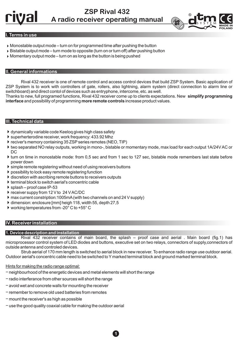
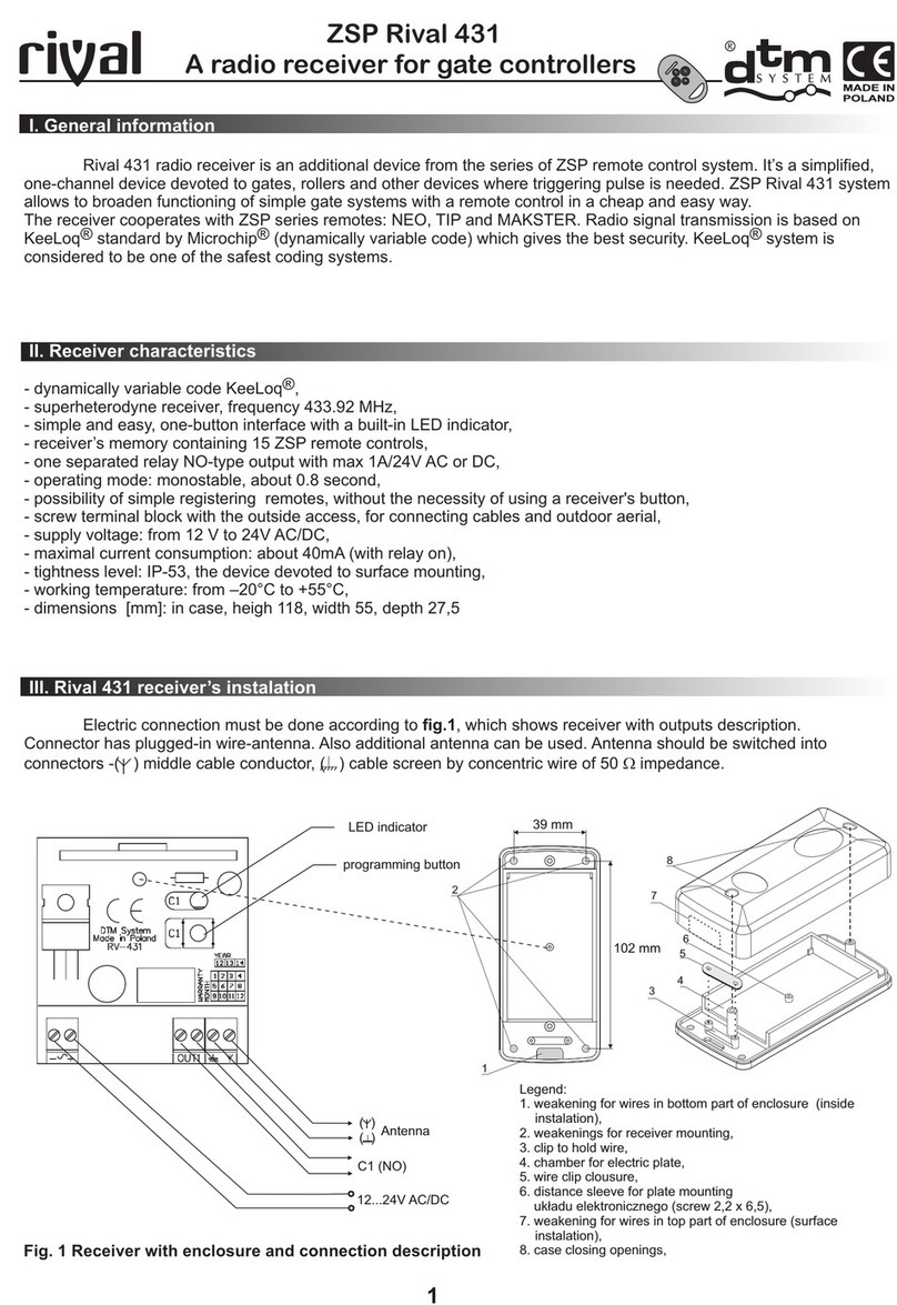
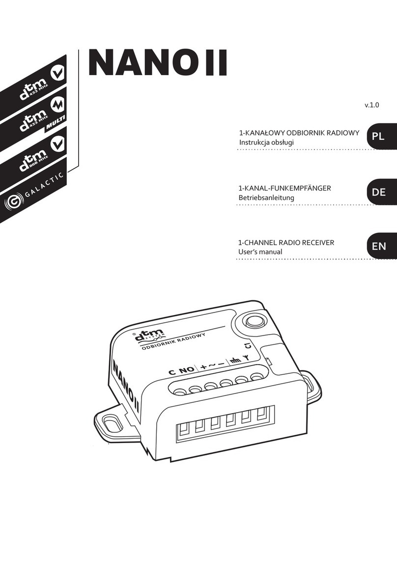
DTM System NANO II Series User manual

MULTI
PL
DE
EN
1-KANAŁOWY ODBIORNIK RADIOWY
Instrukcja obsługi
1-KANAL-FUNKEMPFÄNGER
Betriebsanleitung
1-CHANNEL RADIO RECEIVER
User’s manual
v.1.0

INFORMACJE OGÓLNE
Seria jednokanałowych odbiorników NANO2 przeznaczona jest do współpracy ze sterownikami bram, rolet i innymi
urządzeniami automatyki, gdzie wymagane jest podanie impulsu sterującego. Pozwala w prosty i tani sposób poszerzyć
funkcjonalność instalacji o funkcję zdalnego sterowania.
DANE TECHNICZNE
1. Instalacja odbiornika NANO2
Odbiornik przeznaczony jest do zastosowań
wewnątrz budynków, ewentualnie wewnątrz
obudów innych urządzeń automatyki, przy
zapewnieniu odpowiednich warunków pracy
zgodnych z parametrami technicznymi odbiornika.
Nie należy montować odbiornika w miejscach
narażonych na dużą wilgoć oraz częste i nagłe zmiany
temperatury. Z uwagi na dostępne z zewnątrz złącze
śrubowe, należy zapewnić galwaniczną izolację od
innych urządzeń i przewodów. Należy równiez
zwrócić uwagę na izolacje termiczną od elementów
urządzeń automatyki, które mogą osiągać wysoką
temperaturę (silniki, transformatory, układy
wykonawcze urządzeń sterujących, wszelkie
radiatory, itp.). Podłączenie elektryczne należy
przeprowadzić zgodnie z rys. 1 przedstawiającym
odbiornik z opisem wyprowadzeń. Do zacisku Y
fabrycznie podłączona jest antena drutowa.
Opcjonalnie można użyć anteny zewnętrznej,
podłączając ją przewodem koncentrycznym o
impedancji 50Ω do zacisków Y- środkowa żyła kabla,
- ekran kabla.
2. Programowanie odbiornika
2.1. Wpisywanie pilota do pamięci odbiornika
W celu wpisania pilota do pamięci odbiornika należy
trzymaj ąc je dnocześn ie wciśn ięty przycisk
odbiornika, nacisnąć wybrany przycisk pilota, który
ma zostać dopisany. Kontrolka zamruga sygnalizując
dopisanie, należy zwolnić przycisk odbiornika.
Wybrany przycisk pilota będzie sterować kanałem
wyjściowym odbiornika. W pamięci odbiornika mogą
być wpisane dowolne przyciski danego pilota.
Przytrzymanie przycisku odbiornika powyżej 15 sekund doprowadzi do usunięcia wszystkich pilotów z pamięci
odbiornika.
Próba wpisania kolejnego nadajnika do zapełnionej już pamięci odbiornika zakończy się niepowodzeniem.
12-24V
zasilanie
CNO
antena
2 31 PRZYCISNĄĆ PRZYCISK C1
DIODA ZACZNIE PULSOWAĆ PRZYCISNĄĆ WYBRANY
PRZYCISK PILOTA
C1 ZAMRUGA x3
- DOPISANIE UDANE
ZWOLNIĆ PRZYCISK C1
x3
POLSKI
opis wyprowadzeń
Rys. 1. Widok odbiornika
z opisem wyprowadzeń.
Rys. 2. Wpisywanie pilota.
przycisk programujący
z kontrolką LED

2.2. Zdalne wpisywanie pilota do pamięci odbiornika
Funkcja zdalnego wpisywania pilota pozwala na
dopisanie pilota bez konieczności fizycznego dostępu
do odbiornika.
Wa r un k iem p o wo d z en i a j es t ko n i ec z no ś ć
znajdowania się w zasięgu radiowym odbiornika oraz
posiadanie wcześniej wpisanego pilota.
Aby zdalnie dopisać pilota należy w zasięgu
odbiornika wcisnąć na 15 sekund przycisk już
dopisanego pilota. Następnie w czasie nie dłuższym
niż 3 sekundy wcisnąć i przytrzymać przez 15 sekund
przycisk pilota, który ma zostać dopisany. Nowy pilot zostanie dopisany z identyczną konfiguracją przycisków jak pilot już
dopisany użyty w tej procedurze.
Funkcja zdalnego wpisywania jest niedostępna w przypadku:
źwłączonej blokady zdalnego dopisywania pilotów,
źużycia w procedurze pilotów innych producentów.
Nieudane dopisanie pilota może być spowodowane:
źsłabą baterią któregoś z pilotów,
źzakłóceniami radiowymi, które mogły pojawić się w trakcie trwania procedury zdalnego wpisywania,
źzapełnieniem pamięci odbiornika.
2.3. Zablokowanie / odblokowanie zdalnego wpisywania pilotów
Chcąc zabezpieczyć urządzenie przed nieuprawnionymi próbami dopisania dodatkowego pilota (szczególnie istotne w
obszarach o chronionym dostępie użytkowników), należy zablokować funkcję zdalnego dopisywania pilotów. W celu
zablokowania/odblokowania funkcji zdalnego dopisywania pilotów należy:
źodłączyć zasilanie odbiornika;
źnacisnąć i przytrzymać przycisk C1;
źprzy wciśniętym przycisku włączyć zasilanie;
źdioda C1 zacznie cyklicznie zapalać się i gasnąć (co 5s). Jeśli przycisk zostanie puszczony w chwili, gdy:
dioda C1 świeci – blokada zostanie włączona,
dioda C1 nie świeci – blokada zostanie wyłączona.
2.4. Usuwanie pojedynczego pilota z pamięci odbiornika
W celu usunięcia pojedynczego pilota z pamięci
odbiornika należy trzymając wciśnięty przycisk
odbiornika, nacisnąć aktywny przycisk pilota.
Przytrzymanie przycisku odbiornika
po wyże j 1 5 s ekun d doprowad zi do
usunięcia wszystkich pilotów z pamięci
odbiornika.
2.5. Formatowanie pamięci
W celu sformatowania pamięci odbiornika, należy
nacisnąć i przytrzymać przez 15 sekund przycisk
odbiornika. Przycisk należy zwolnić dopiero gdy
kontrolka zgaśnie.
Formatowanie pamięci:
źusuwa wszystkie piloty z odbiornika,
źwyłącza blokadę zdalnego wpisywania pilotów.
2.6. Kontrola liczby wpisanych pilotów
W celu sprawdzenia liczby pilotów wpisanych do pamięci odbiornika, należy po operacji wpisania lub usunięcia pilota,
przytrzymać wciśnięty przycisk w odbiorniku jeszcze przez ok. 5 sekund. Kontrolka zacznie pulsować wskazując liczbę
zaprogramowanych pilotów. Kolejno pokazywana jest liczba dziesiątek (długi impuls) następnie cyfra jedności (od 0 do 9
krótkich impulsów).
1WCISNĄĆ NA 15s
PRZYCISK
"STAREGO" PILOTA
PO MAKSYMALNIE
3 SEKUNDACH
PILOT W ZASIĘGU
ODBIORNIKA
2WCISNĄĆ NA 15s
PRZYCISK
"NOWEGO" PILOTA
PILOT W ZASIĘGU
ODBIORNIKA
2 31 PRZYCISNĄĆ PRZYCISK C1
DIODA ZACZNIE PULSOWAĆ PRZYCISNĄĆ
PRZYCISK PILOTA
C1 ZGAŚNIE
- USUNIĘCIE UDANE
ZWOLNIĆ PRZYCISK C1
1 2 PO OKOŁO 15 SEKUNDACH
DIODA ZGAŚNIE - KONIEC
PROCESU FORMATOWANIA
> 15s
Rys. 6. Przykład impulsów pokazujących liczbę wpisanych pilotów - 46 sztuk.
liczba dziesiątek - 4x10 liczba jednostek - 6
POLSKI
Rys. 3. Zdalne wpisywanie pilota.
Rys. 4. Usunięcie pilota.
Rys. 5. Formatowanie pamięci.
PRZYCISNĄĆ PRZYCISK C1
DIODA ZACZNIE PULSOWAĆ

DEUTSCH
ALLGEMEINE INFORMATIONEN
Die Serie der 1-Kanal-Funkempfänger NAN02 ist für Zusammenarbeit mit den Einfahrtstor-, Rollos-Steuerungen sowie mit
anderen Anlagen der Automatiktechnik ausgelegt, bei denen Sendung eines Steuerungsimpulses erforderlich ist. Die Serie
macht es möglich, Funktionalität der Anlage um einen Handsender einfach und günstig zu erweitern.
TECHNISCHE DATEN
1.Installation des NANO2 Funkempfängers
Der Funkempfänger eignet sich für Verwendungen im
I n ne nb e re ic h , g gf. in G e h ä u s en an d er e r
auto m a t i sc he r Ge r ät e, be i Sich e r s t e llung
entsprechender, mit technischen Parametern des
E m p f ä n g e r s ü b e r e i n s t i m m e n d e r
Betriebsbedingungen. Der Funkempfänger sollte an
keinen gegen hohe Feuchtigkeit sowie häufige und
plötzliche Temperaturschwankungen ausgesetzten
Stellen montiert werden. In Anbetracht von außen
zugänglicher Schraubverbindung ist für eine
galvanische Isolierung von anderen Geräten und
Kabeln zu sorgen. Ferner ist eine Wärmedämmung
von Bauteilen automatischer Geräte, die eine hohe
Temperatur erzeugen können (Motoren, Trafos,
ausführende Systeme von Steuergeräten, sämtliche
Radiatoren etc.) zu beachten. Der elektrische
Anschluss hat gemäß Abb. 1 mit der Darstellung des
Funkempfängers und Beschreibung der Eingaben zu
erfolgen. An der Y-Klemme ist werkseitig eine
Drahtantenne angeschlossen. Optional kann eine
externe Antenne verwendet werden. Diese ist mit
einem Koaxialkabel mit einer Impedanz von 50 Ω an
d e n Y- K l e m m e n – m i t t l e r e K a b e l a d e r ,
-Kabelschirmung anzuschließen
2.Programmieren des Funkempfängers
2 . 1 . S p e i c h e r n d e s H a n d s e n d e r s i m
Funkempfänger
Zum Speichern des Handsenders im Funkempfänger
ist die Taste des Empfängers gedrückt zu halten,
dabei ist gleichzeitig die gewählte Taste des zu
speichernden Handsenders zu drücken. Nachdem die
blinkende LED ein erfolgreiches Speichern
signalisiert, ist die Taste des Funkempfängers loszulassen. Die gewählte Handsendertaste steuert mit dem Ausgangskanal des
Funkempfängers. Im Speicher des Funkempfängers können beliebige Tasten des jeweiligen Handsenders eingegeben werden.
Indem die Taste des Funkempfängers länger als 15 Sekunden gedrückt gehalten wird, werden alle Handsender aus
dem Speicher des Funkempfängers gelöscht.
Der Versuch, einen weiteren Handsender im bereits vollen Speicher des Funkempfängers zu speichern, scheitert.
12-24V
Spannungsversorgung
CNO Antenne
2 31 TASTE C1 DRÜCKEN,
DIE LED FÄNGT
ZU BLINKEN AN
DIE AUSGEWÄHLTE TASTE
DES HANDSENDERS
DRÜCKEN
C1 BLINKT 3x
– EINGABE ERFOLGREICH
DIE TASTE C1 LOSLASSEN
x3
Beschr. der Eingaben
Abb. 1. Ansicht
des Funkempfängers inkl.
Beschr. der Eingaben.
Abb. 2. Speichern des Handsenders.
Programmiertaste
mit LED
Speicher
Frequenz
Spannungsversorgung
Stromaufnahme
Ausgang
Ausgangslast
Betriebsmodus
Temperatur
Schutzart
Abmessungen
Abmessungen
inkl. Montagehalterungen
ca. 30 mA (bei eingeschaltetem Relais)
15 Handsender
DTM433MHz
+ anderer Hersteller
15 Handsender
DTM433MHz
+ anderer Hersteller
150 Handsender
DTM433MHz
150 Handsender
DTM433MHz
-20°C / +55°C
Ein separater NO-Relais-Ausgang
Monostabil, mit Stand-by 1s

DEUTSCH
2.2. Ferngesteuertes Speichern des Handsenders im Funkempfänger
Die Funktion der ferngesteuerten Speicherung des
Handsenders macht es möglich, den Handsender
ohne physischen Zugang zum Funkempfänger
hinzufügen.
Eine Voraussetzung für erfolgreiche Speicherung ist
es, sich in der Funkreichweite des Funkempfängers
notwendigerweise aufzuhalten sowie über einen
vorher gespeicherten Handsender zu verfügen.
Um einen Handsender ferngesteuert hinzufügen,
halten Sie sich in der Reichweite des Funkempfängers auf und drücken Sie 15 Sekunden lang die Taste des bereits zugefügten
Handsenders. Anschließend drücken Sie nach max. 3 Sekunden und halten 15 Sekunden lang eine Taste des zu speichernden
Handsenders gedrückt. Der neue Handsender wird mit einer identischen Tastenkonfiguration wie bei dem bereits
gespeicherten, bei diesem Verfahren eingesetzten Handsender, gespeichert.
Die Funktion für ferngesteuertes Speichern ist nicht zugänglich, wenn:
źDas ferngesteuerte Speichern von Handsendern blockiert ist,
źBei dem Verfahren Handsender anderer Hersteller verwendet werden.
Mögliche Ursachen eines erfolglosen Hinzufügens des Handsenders:
źHandsender-Batterie eines der Handsender schwach,
źFunkstörungen beim Hinzufügen über Funk,
źSpeicher des Funkempfängers voll.
2.3. Blockieren/Freigabe ferngesteuerter Speicherfunktion
Zum Schutz des Gerätes vor unbefugtem Speichern eines zusätzlichen Handsenders (insbesondere in zugriffsgeschützten
Bereichen), ist die Funktion für ferngesteuertes Speichern der Handsender zu blockieren. Zu diesem Zweck:
źEmpfängerversorgung trennen;
źTaste C1 drücken und gedrückt halten;
źBei gedrückter Taste die Versorgung einschalten;
źdie C1-LED fängt an abwechselnd aufzuleuchten und zu erlöschen (alle 5s). Wird die Taste losgelassen, wenn:
die C1-LED leuchtet – wird die Blockade aktiviert;
die C1-LED erlischt – wird die Blockade deaktiviert.
2.4.Löschen einzelner Handsender aus dem Funkempfänger-Speicher
Zum Löschen eines einzelnen Handsenders vom
Funkempfänger-Speicher ist die Empfängertaste
gedrückt zu halten, dabei ist die aktive Taste am
Handsender zu drücken.
Indem die Taste des Funkempfängers
länger als 15 Sekunden gedrückt gehalten
wird, werden alle Handsender aus dem
Speicher des Funkempfängers gelöscht.
2.5. Formatierung des Speichers
Z u r F o r m a t i e ru ng de s S p e i c h e r s i s t d i e
Empfängertaste zu betätigen und 15 Sekunden lang
gedrückt zu halten. Die Taste ist erst loszulassen,
wenn die LED erloschen ist.
Formatierung des Speichers:
źL ö s c h t a l l e H a n d s e n d e r a u s d e m
Funkempfänger;
źDeaktiviert die Blockade für ferngesteuertes
Speichern von Handsendern.
2.6. Prüfung der Anzahl gespeicherter Handsender
Zur Prüfung der Anzahl gespeicherter Handsender ist nach erfolgreichem Speichern oder Löschen eines Handsenders die
Empfängertaste noch ca. 5 Sekunden lang gedrückt zu halten. Die LED zeigt durch Pulsieren die Anzahl gespeicherter
Handsender an. Es wird nachfolgend die Anzahl der Zehnerstellen (langer Impuls) und die Anzahl der Einerstellen (0 bis 9 kurze
Impulse) angezeigt.
1DIE TASTE DES "ALTEN"
HANDSENDERS FÜR
15 SEKUNDEN DRÜCKEN
NACH MAXIMAL 3 SEKUNDEN
HANDSENDER IN REICHWEITE
DES FUNKEMPFÄNGERS
2
2 31 TASTE C1 DRÜCKEN,
DIE LED FÄNGT
ZU BLINKEN AN
DIE TASTE DES
HANDSENDERS DRÜCKEN
C1 ERLISCHT
– ERFOLGREICH GELÖSCHT
DIE TASTE C1 LOSLASSEN
1 2 NACH CA. 15 SEKUNDEN
ERLISCHT DIE LED
– ENDE DER FORMATIERUNG
> 15s
Abb. 6. Beispiel der Impulse zur Darstellung der Anzahl gespeicherter Handsender – 46 Stück.
Anzahl der Zehnerstellen - 4x10 Anzahl der Einerstellen - 6
Abb. 3. Ferngesteuertes Speichern des Handsenders.
Abb. 4. Löschen eines Handsenders
Abb. 5. Formatierung des Speichers.
TASTE C1 DRÜCKEN,
DIE LED FÄNGT
ZU BLINKEN AN
HANDSENDER IN REICHWEITE
DES FUNKEMPFÄNGERS
DIE TASTE DES "NEUEN"
HANDSENDERS FÜR
15 SEKUNDEN DRÜCKEN

ENGLISH
GENERAL INFORMATION
The series of 1-channel radio receivers NANO2 is designed to work with gate controllers, roller shutters and other automation
devices where a control pulse is required. It allows, in a simple and cost-effective way, to extend the installation functionality
with a remote control.
TECHNICAL DATA
1.Installation
Receiver is designed for use inside buildings or inside
other automation devices. Ensure proper operation
condidtions in line with technical parameters. Do not
mount in locations exposed to high humidity and
frequent sudden temperature changes.
Due to the externally accesible screw connection
provide galvanic isolation from other devices and
wires. Attention should be paid to thermal insulation
of automation elements which can reach high
temperatures (motors, transformers, circuits
implementing, heat sink etc.). For electrical
connection see Fig. 1.
Factory wire antenna is connected to antenna
terminal. Optionally external antenna can be used.
Connect external antenna with 50Ω impedance
coaxial cable to Y - center core, - shield.
2. Receiver programming
2.1. Adding the remote control into the receiver's
memory
In order to add the remote control into the receiver's
memory, press the receiver button and press the
selected remote control button. The LED blinks
indicating the add, release the receiver button. The
selected button of the remote control will control the
output channel of the receiver. Any button of the
remote control can be added in the receiver's
memory.
Holding down the receiver button for more than 15 seconds will remove all the remote controls from the receiver.
Attempting to add another remote control into the already-filled memory of the receiver will fail..
12-24V
power
CNO
antenna
2 31 PRESS C1 BUTTON
LED PULSES PRESS REMOTE CONTROL
BUTTON
C1 BLINKS x3
- ADDING SUCCESSFUL,
RELEASE C1 BUTTON
x3
pin description
Fig. 1. View of the receiver
with pin description.
Fig. 2. Adding a remote control.
programming
button with LED
memory
frequency
power supply
power consumption
output
output load
operation mode
temperature
ingress protection
dimensions
dimensions
with mouting brackets
Approx. 30mA (with relay ON)
15 remotes
DTM433MHz +other producers
15 remotes
DTM433MHz
+other producers
150 remotes
DTM433MHz
150 remotes
DTM433MHz
-20°C / +55°C
one, separated NO type
monostable, turn-on time 1s

PL
ENGLISH
ENGLISH
2.2. Easy remote control adding
Easy remote control adding function allows adding a
remote control without access to receiver.
Previously added remote is needed.
For easy remote control adding press and hold for 15
seconds, already added remote control button in
receiver radio range. In no more than 3 seconds press
and hold new remote control button for 15 seconds.
New remote is added with the same button
configuration as in previously added remote control
used in the procedure.
Easy remote control adding function is disabled if:
źthe function is locked,
źuse in the procedure remote controls of other manufacturers.
Failure in remote control adding may be caused by:
źa low battery of any of remote controls,
źradio interference that may have occurred during the procedure,
źa full memory of the receiver.
2.3. Locking/unlocking easy remote control adding function
To protect receiver against unauthorized attempts of adding a remote control (important in access protected user zones) easy
remote control adding function must be locked. To lock/unlock easy remote control adding function:
źturn off receiver power supply,
źpress and hold C1 button
źturn on receiver power supply
źC1 LED will alternately light on and light off every 5 seconds. If the C1 button will be released when:
C1 light on - easy remote control adding function is locked;
C1 light off - easy remote control adding function is unlocked.
2.4. Deleting a single remote control from the receiver's memory
To remove a single remote from the receiver's
memory, hold down the receiver button and press
the active remote control button.
Holding down the receiver button for more
than 15 seconds will remove all the remote
controls from the receiver.
2.5. Memory format
To format the receiver's memory, press and hold the
receiver button for 15 seconds. Release the button
only when the light goes out.
Memory format:
ź removers all remote controls from the receiver,
ź disables the easy remote adding lock.
2.6. Verifying the number of added remote controls
In order to check the number of remote controls in the receiver's memory, keep pressed for 5 seconds the button of the receiver
after adding or deleting a remote control. The LED flashes indicating the number of added remotes. First the number of tens
(long pulse) followed by the unity number (from 0 to 9 short pulses).
1PRESS AND HOLD
FOR 15 SECONDS
„OLD” REMOTE BUTTON
AFTER MAX 3 SECONDS
REMOTE IN RECEIVER
RADIO RANGE
2PRESS AND HOLD
FOR 15 SECONDS
„NEW” REMOTE BUTTON
REMOTE IN RECEIVER
RADIO RANGE
2 31 PRESS AND HOLD C1
LED PULSES PRESS ACTIVE REMOTE
CONTROL BUTTON
C1 LIGHTS OUT
- DELETING SUCCESSFUL
RELEASE C1 BUTTON
1 2 AFTER 15 SECONDS
LED GOES OUT
- FORMAT COMPLETED
> 15s
Fig. 6. An example of pulses showing the 46 remote controls.
number of tens - 4x10 number of unity - 6
Fig. 3. Easy remote control adding.
Fig. 4. Deleting a single remote control.
Fig. 5. Memory format.
PRESS AND HOLD
C1 BUTTON

DISPOSAL
Electrical or electronic devices cannot be
removed with everyday waste. The correct
recycling of devices gives the possibility of
keeping natural resources of the Earth for a
longer time and prevents the degradation
of natural environment.
WARRANTY
DTM System provides operational and
ready to use devices and gives 24 months
warranty from the selling date to the end
customer. This time is counted according
to the producer warranty labels or serial
numbers placed on every product. DTM
System obliges itself to repair the device
for free if during the warranty period there
are problems which come because of its
fault. Broken device should be supplied on
customer’s expense to the place of
purchase and enclose clear and brief
description of the breakage. The cost of
mount/dismount is covered by the user.
The warranty does not cover any faults
caused by improper usage, user self
repairs, regulations and adaptations,
lightning strikes, voltages or short circuits
in the electrical grid. Appropriate legal acts
regulate details of the warranty.
ENTSORGUNG
Entsorgung der Elektrogeräte bzw.
Elektronik darf nicht in Rahmen der
Hau sh a l tsa bf ä l le erf ol g e n. E ine
sachgerechte Entsorgung des Gerätes
m a c h t e s m ö g l i c h , n a t ü r l i c h e
Erdressourcen länger aufrecht zu erhalten
s o w i e d e r U m w e l t z e r s t ö r u n g
vorzubeugen.
GARANTIEBEDINGUNGEN
Der Hersteller DTM System übergibt
funktionsfähige und nutzungsbereite
Geräte. Der Hersteller erteilt eine Garantie
von 24 Monaten nach Einkaufsdatum vom
Endkunden gerechnet. Die Garantiezeit
wird auf Basis von Garantieblomben des
Herstellers, die an jedem Erzeugnis
angebracht werden, festgelegt. Der
Hersteller verpflichtet sich dazu, das Gerät
kostenfrei zu reparieren, wenn in der
Garantiezeit Mängel durch Verschulden
de s He rs te l le rs a uf tre te n. N ich t
funktionsfähiges Gerät ist auf eigene
Rechnung an die Einkaufsstelle zu liefern.
D e r L i e f e r u n g i s t e i n e k u r z e ,
nachvollziehbare Beschreibung des
Schadens beizufügen. Die Demontage-
und Montagekosten gehen zu Lasten des
Betreibers. Die Garantie gilt nicht für
Batterien in den Handsendern, sämtliche
Schäden, die durch unsachgemäße
Verwendung, selbsttätige Regelungen,
Modifikationen und Reparaturen sowie
Schäden infolge von atmosphärischen
Entladungen, Überspannungen bzw.
K u r z s chlüssen d e s Stromn et z e s
entstanden sind. Detaillierte Bedingungen
für Garantieerteilung werden in den
einschlägigen Rechtsnormen geregelt.
UTYLIZACJA
U r z ą d z e ń e l e k t r y c z n y c h l u b
elektronicznych nie można wyrzucać
razem z odpadami gospodarczymi.
Prawidłowa utylizacja urządzenia daje
możliwość zachowania naturalnych
zasobów Ziemi na dłużej i zapobiega
degradacji środowiska naturalnego.
WARUNKI GWARANCJI
Producent DTM System, przekazuje
urządzenia sprawne i gotowe do użytku.
Producent udziela gwarancji na okres 24
miesięcy od daty zakupu przez klienta
końcowego. Okres gwarancji określany
jest na podstawie plomb gwarancyjnych
producenta, umieszczanych na każdym
wyrobie. Producent zobowiązuje się do
bezpłatnej naprawy urządzenia, jeżeli w
okresie gwarancji wystąpiły wady z winy
producenta. Niesprawne urządzenie
należy dostarczyć na własny koszt do
miejsca zakupu, załączając kopie dowodu
zakupu i krótki, jednoznaczny opis
uszkodzenia. Koszt demontażu i montażu
urządzenia ponosi użytkownik. Gwarancja
nie obejmuje baterii w pilotach, wszelkich
uszko dzeń po ws tałych w w yn ik u
n i ep r a wi d ł ow e g o u ż yt ko w a n ia ,
samowolnych regulacji, przeróbek i
napraw oraz uszkodzeń powstałych w
wyniku wyładowania atmosferycznego,
przepięcia lub zwarcia sieci zasilającej.
Sz cze gó ł ow e war un k i ud zie la n ia
gwarancji regulują stosowne akty prawne.
D T M S y s t e m
niniejszym oświadcza,
że odbiornik radiowy
j e s t z g o d n y z d y r e k t y w ą
2014/53/UE. Pełny tekst deklaracji
zgodności UE jest dostępny pod
adresem internetowym.
DTM System erklärt
h i er m i t , d a ss d e r
Funkempfänger mit
der Richtlinie 2014/53/EU konform
i s t . D e r V o l l t e x t d e r E U -
Konformitätsbestätigung ist unter
unser Website zugänglich.
DTM System hereby
declares that the radio
receiver complies with
Directive 2014/53 / EU. The full text
of the EU Declaration of Conformity
is available at the Internet address.
DTM System spółka z ograniczoną odpowiedzialnością spółka komandytowa
ul. Brzeska 7, 85-145 Bydgoszcz, Polska, tel. +48 52 340 15 83, www.dtm.pl
Other manuals for NANO II Series
1
This manual suits for next models
3
Table of contents
Languages:
Other DTM System Receiver manuals

DTM System
DTM System Rival 431 User manual

DTM System
DTM System UVR-2 User manual

DTM System
DTM System SPC-433 User manual

DTM System
DTM System PIKO User manual

DTM System
DTM System MAX II User manual

DTM System
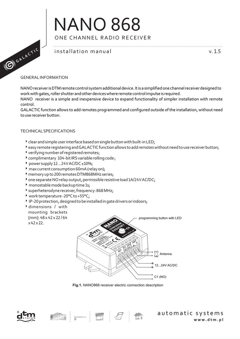
DTM System GALACTIC NANO 868 User manual

DTM System
DTM System cloud FLEX Manual

DTM System
DTM System S-FIX User manual

DTM System
DTM System PERFECT SOS User manual

DTM System
DTM System mini User instructions