Du Pont Sorvall RC-5B Plus User manual

~~~~~~~~ Centrifuges
This manual is a guide to the service of the
~~~~~~~ RC-5B PLUS ~~~~~~~~~~ Centrifuge
Data herein has been verified and validated and is believed adequate for the intended use of the
instrument. Because failure to follow the recommendations set forth in this manual could produce
personal injury or property damage, always follow the recommendations set forth herein. ~~~~~~ does
not guarantee results and assumes no obligation for the performance of products that are not used in
accordance with the instructions provided. This publication is not a license to operate under, nor a
recommendation to infringe upon any process patents.
This service manual is intended for use only by qualified service personnel. Due to the high electrical
potential in these instruments, untrained personnel must not attempt any of the procedures contained in
this service manual.
This service manual is intended as a service aid. While the manual is kept current and includes
information regarding significant design changes, specific designs may still vary from instrument to
instrument.
WARNING, CAUTION, and NOTE within the text of this manual are used to emphasize important
and critical instructions.
WARNING informs the operator of a hazard or an unsafe practice that could result in personal
injury, affect the operator's health, or contaminate the environment.
CAUTION informs the operator of an unsafe practice that could result in damage of equipment.
NOTE highlights essential information.
CAUTION and WARNING are accompanied by a hazard symbol ~~~ and appear in the left
~~~~~~~ near the information they correspond to.

~~~~~~~~ Centrifuges Important Safety Information
Important Safety Information
Certain potentially dangerous conditions are inherent to the use of all centrifuges. To ensure
safe operation of this centrifuge, anyone using it should be aware of all safe practices and take
all precautions described below and throughout this manual.
A ~\ WARNING
When using radioactive, toxic, or pathogenic materials~ be aware of all characteristics of the materials and
the hazards associated with them in the event leakage occurs during ~~~~~~~~~~~~~~~ In the event of a rotor
failure, neither the centrifuge nor the rotor can protect you from particles dispersed in the air. To protect
yourself, we recommend additional precautions be taken to prevent exposure to these materials, for
example, use of controlled ventilation or isolation areas.
Always be aware of the possibility of contamination when using radioactive, toxic, or pathogenic
materials. Take all necessary precautions and use appropriate ~~~~~~~~~~~~~~~ procedures if exposure
occurs.
Never use any material capable of producing flammable or explosive vapors.
Never exceed the maximum rated speed of the installed rotor; to do so can cause rotor failure.

Table of Contents ~~~~~~~~ Centrifuges
Ta~le of Contents
Page
Disclaimer...................................................... ~~
Sec~~on 1. INTRODUCTION & DESCRIPTION
1-1. Intended Use .............................................. 1-1
1-2. Centrifuge Description...................................... 1-1
1-3. Centrifuge Accessories ...................................... 1-2
1-4. Centrifuge Warranty ........................................ 1-3
1-5. Service ~~~~~~~~~~~~~~~ Policy .............................. 1-3
Section 2. INSTALLATION
2-1. Inspection................................................. 2-1
2-2. Location Requirements...................................... 2-1
2-3. Electrical Requirements ..................................... 2-1
2-4. Installation ................................................ 2-2
2-5. Rewiring the Centrifuge..................................... 2-3
Conversion to Single~Phase Permanent Wiring ................. 2-3
2-6. Test Run Procedure ......................................... 2-4
Section 3. OPERATION
3-1. Setting Centrifuge Power On ................................ 3-1
3-2. Opening the Chamber Door ................................. 3-1
3-3. Centrifuge Controls Description.............................. 3-1
3-4. Centrifuge Operation ....................................... 3-3
3-5. Rotor Speed/Temperature Differential Compensation........... 3-4
3-6. Precautions to Prevent Samples from Freezing ................. 3-5
3-7. Rotor ~~~~~~~.............................................. 3-7
3-8. Troubleshooting............................................ 3-8
3-9. Reducing Speeds for Loads in Excess of Design Mass ........... 3-9
Sect~on 4. SPECIFICATIONS
4-1. Centrifuge Specifications .................................... 4-1
Rotor Information Table ....................................... 4-3
Section 5. PRINTED CIRCUIT BOARDS &
SCHEMATIC DIAGRAMS
IV

RC-5B PLUS ~ Table of Contents
Section 6. CALIBRATION
6~1. Precautions for Handling Printed Circuit Boards
6~2. Calibration Sequence ........................
6~3. Calibration Criteria and Adjustment Locations ~ ~~6~4.
Test Equipment Required.....................
6-5. Calibration Procedures.......................
Section 7. ILLUSTRATED PARTS
Section 8. PREVENTIVE MAINTENANCE
NOT YET AVAILABLE
Section 9. REPAIR & REPLACEMENT
NOT YET AVAILABLE
Section 10~ SYSTEM DESCRIPTIONS
NOT YET AVAILABLE
Section 11~ TROUBLESHOOTING
11-1. Emergency Sample Recovery ..................
11-2. General Troubleshooting (NOT YET AVAILABLE)
Page
6~1
6-2
6-2
6~2
6-2
11-1
11-2

Table of Contents ~~~~~~~~ Centrifuges
Tall~es
Page
3-1. Centrifuge Controls ............................................ 3-2
3~2. Troubleshoo~~ng................................................ 3-8
5-1. Component Description, Controller Printed Circuit Board ........... 5-15
5-2. Component Description, Lower Control Printed Circuit Board ....... 5-25
6~1. Calibration Sequence ........................................... 6-5
6~2. Imbalance Detection Threshold .................................. 6-11
6~3. Test Point Descriptions for Controller ~~~~ Board, ~~ 74095 .......... 6-14
6~4. Potentiometer Adjustment for Controller P.C. Board, PN 74095 ....... 6-15
7-1. RC-5B PLUS Assembly, Front View ............................... 7-3
7-2. RC-5B PLUS Assembly, Right View ............................... 7-5
7-3. RC-5B PLUS Assembly, Rear View ................................ 7-7
7-4. RC-5B PLUS Panel Assembly, Main Breaker........................ 7-8
7-5. RC-5B PLUS Front Console Panel Assembly ....................... 7-9
7-6. RC-5B PLUS Evaporator Assembly ............................... 7-11
7-7. RC-5B PLUS Drive Assembly .................................... 7-13
7-8. RC-5B PLUS Motor Assembly~................................... 7-15
7-9. RC-5B PLUS Door Interlock Assembly, Part A ...................... 7-17
7-10 RC-5B PLUS Door Interlock Assembly, Part ~ ...................... 7-19
7-11. RC-5B PLUS Constant Current Brake Assembly .................... 7-21
VI
---------
---------
12987
12987

RC-5B PLUS Table of Contents
Illustrations
Page
1-1. Centrifuge Parts Location and Identification ....................... 1-2
2-1. Single~Phase Permanent Wiring .................................. 2-4
3-1. RC-5B PLUS Control Panel ...................................... 3-3
5-1. System Diagram ............................................... 5-3
5-2. Schematic for Controller ~~~~ Board Assembly, ~~ 74095 (4 sheets) ... 5-5
5-3. Component Location: Controller Printed Circuit Board ...~.......... 5-13
5-4. Schematic for Lower Control Printed Circuit Board, ~~ 74089........ 5-21
5-5. Component Location: Lower Control Printed Circuit Board .......... 5-23
6~1. Test Point and ~~~~~~~~~~~ Locations for Controller P.C.
Board Assembly, PN 74095 ..................................... 6-4
6~2. Test Set-Up for Temperature Meter Deflection Adjustment........... 6-7
7-1. RC-5B PLUS Assembly, Front View ............................... 7-2
7-2. RC-5B PLUS Assembly, Right View ............................... 7-4
7-3. RC-5B PLUS Assembly, Rear View................................ 7-6
7-4. RC-5B PLUS Panel Assembly, Main Breaker. ....................... 7-8
7-5. RC-5B PLUS Front Console Panel Assembly ....................... 7-9
7-6. RC-5B PLUS Evaporator Assembly ............................... 7-10
7-7. RC-5B PLUS Drive Assembly .................................... 7-12
7-8. RC-5B PLUS Motor Assembly.................................... 7-14
7-9. RC-5B PLUS Door Interlock Assembly, Part A ...................... 7-16
7-10. RC-5B ~LUS Door Interlock Assembly, Part ~ ...................... 7-19
7-11. RC-5B PLUS Constant Current Brake Assembly .................... 7-20
11-1. Emergency Sample Recovery .................................... 11-1
~~~~~~~~
--------
74306
--------
12987
---------
12987

RC-5B PLUS In~roduction & Description
Section 1: I~TRODUCTIO~ & DESCRIPTIO~
This manual is a service guide for the SORVALL~~~ RC-5B PLUS ~~~~~~~~~~ Refrigerated Centrifuge. It
contains descriptive information, mechanical and electrical theories of operation, maintenance procedures,
calibrations, and an illustrated parts list for ordering replacements.
A IV A ~ ~ I ~ ~
To avoid personal injury, all
replacement and calibration proce¬
dures should be performed by quali¬
fied service personnel.
1-1. Intended Use
This manual is for qualified service personnel who are familiar with
electronics and factory methods for performing repairs, adjust¬
ments, and calibrations. It provides a fault isolation method that
isolates and identifies the cause of a problem within the centrifuge,
a parts list, and information for ordering replacement parts needed
for the repair of parts or systems within the centrifuge.
Warnings, Cautions, and Notes are used throughout this manual to
emphasize important and critical instructions. Service personnel
are expected to be familiar with their meaning (see page ~~~ and to
read them before servicing the centrifuge.
1-2. Centrifuge Description
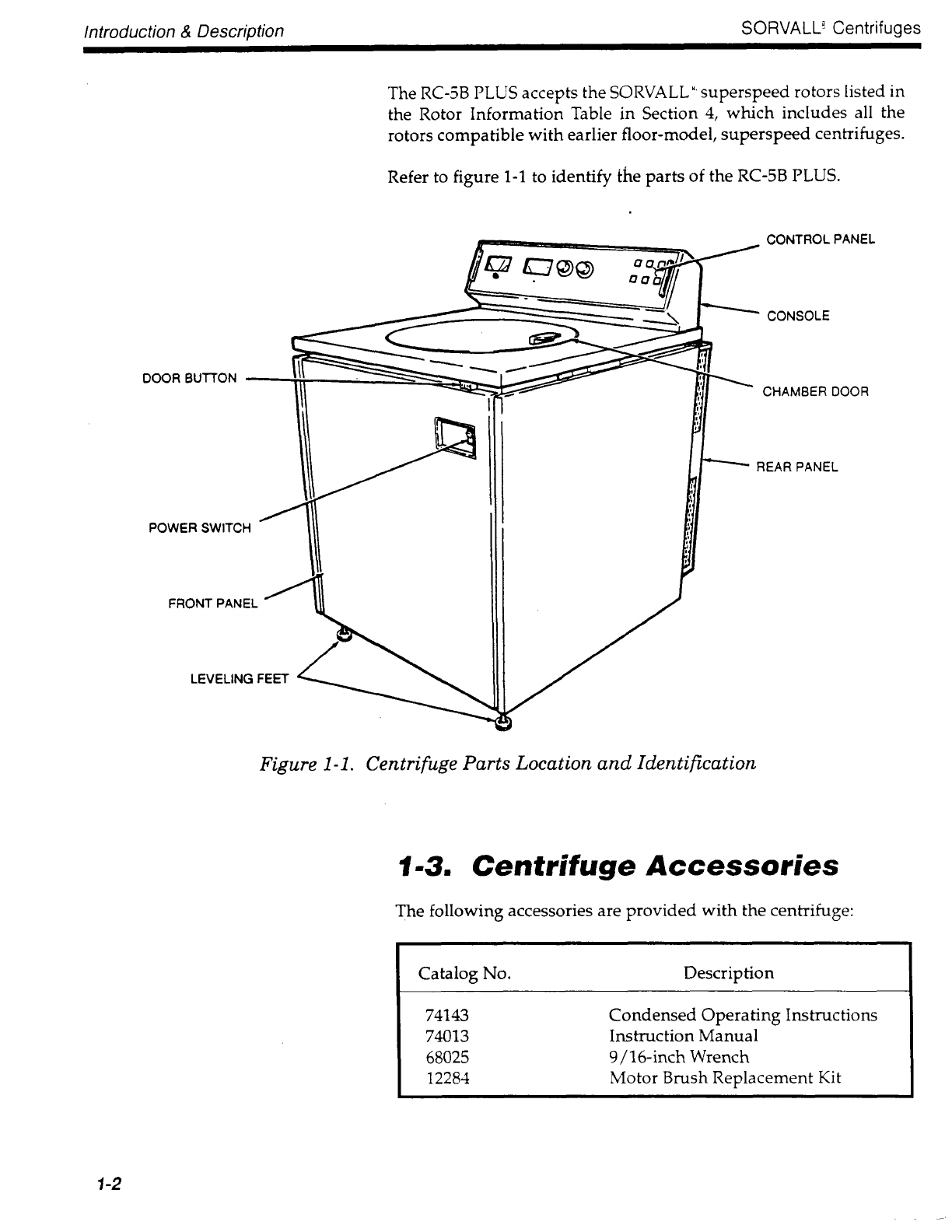
The RC-5B PLUS is a high-speed (to 21 000 ~~~~~ floor-model
centrifuge used to separate substances of different densities at
controlled temperatures. Its function is to increase the effects of
gravity by centrifugal force to separate substances of different size
or densities at controlled temperatures.
The centrifuge has a fan-cooled motor that is balanced and enclosed
in an air-cooled silencer to ensure smooth, quiet operation over its
full speed range and to promote long life for the brushes and
bearings. The durable motor brushes have increased life and the
gyro-action self-centering drive spindle allows you to balance the
centrifuge tubes by "eye" rather than by weighing them.
The refrigeration system is a low-temperature, hermetically-sealed
unit consisting of a compressor, condenser, evaporator/rotor
chamber and interconnecting tubing. It is charged with SUVA~~~refrigerant,
one of ~~~~~~~~ ~~~~~~~~~~~~~~~ coolants. During
operation, the cooling system will maintain rotor compartment
temperature within 1°C ~~~~~~~~~~~
Run parameters are selected ~~ setting the dials on the front control
panel. Actual run conditions are continuously displayed during
operation by easy-to-read analog displays.

Introduction & Description SORVALL" Centrifuges
DOOR BUTTON
POWER SWITCH
FRONT PANEL
LEVELING FEET
The RC-5B PLUS accepts the SORVALL~~ ~~~~~~~~~~ rotors listed in
the Rotor Information Table in Section 4, which includes all the
rotors compatible with earlier floor-model, superspeed centrifuges.
Refer to figure 1-1 to identify ~he parts of the RC-5B PLUS.
CONTROL PANEL
CONSOLE
CHAMBER DOOR
REAR PANEL
Figure 1-1. Centrifuge Parts Location and Identification
1-3. Centrifuge Accessories
The following accessories are provided with the centrifuge:
Catalog No.
74143
74013
68025
12284
Description
Condensed Operating Instructions
Instruction Manual
9~16-inch Wrench
Motor Brush Replacement Kit
1-2

RC-5B PLUS Introduction & Description
1-4. Centrifuge Warranty
~~ I. ~~~~~~ ~~ ~~~~~~~ and Company makes no warranty of any
kind, expressed or implied, except as stated in this warranty policy.
The ~~~~~~~~ RC-5B PLUS ~~~~~~~~~~ Centrifuge is warranted
to be free from defects in material and workmanship for a period of
one year from the date of delivery. The compressor, condenser~~evaporator
and all interconnecting tubing are warranted to be free
of defects in material and workmanship for a period of five years
from the date of delivery. DuPont will repair or replace and return
free of charge any part which is returned to its factory within said
period, transportation prepaid by user, and which is found upon
inspection to have been defective in materials or workmanship.
This warranty does not apply to any damage to any instrument
resulting from: normal wear and tear; misuse; abuse; use of electrical
currents or circuits other than those specified on the plate affixed to
the instrument; accident; negligence; failure to follow operating
instructions; or use of any rotor other than a ~~~~~~~~~ rotor
intended for use in this instrument.
DuPont reserves the right to change, alter, modify, or improve any
of its instruments without any obligation whatsoever to make cor¬
responding changes to any instrument previously sold or shipped.
The foregoing obligations are in lieu of all other obligations and
liabilities including negligence and all warranties, of merchant-
ability or otherwise, expressed or implied in fact or by law, and
state our entire and exclusive liability and buyer's exclusive rem¬
edy for any claim or damages in connection with the sale or
furnishing of goods or parts, their design, suitability for use,
installation or operation. DuPont will in no event be liable for any
special or consequential damages whatsoever, and our liability
under no circumstances will exceed the contract price for the
goods for which liability is claimed.
A ~ A ~ ~ ~ ~
Because of the character¬
istics of the samples likely to be pro¬
cessed in this centrifuge, biological
or radioactive contamination may oc¬
cur. Always be aware of this possibil¬
ity, and take normal precautions. Use
appropriate ~~~~~~~~~~~~~~~ proce¬
dures should exposure occur.
1-5. Service Decontamination
Policy
If a centrifuge or rotor that has been used with radioactive or
pathogenic material requires servicing by DuPont personnel, either
at the customer's laboratory or at a DuPont facility, comply with
the following procedure to ensure the safety of all personnel:
1. Clean the cent~ifuge or rotor to be serviced of all encrusted
material and decontaminate it (see "Cleaning and
Decontamination" on page 4-2 of the RC-5B PLUS Operator
Manual) prior to servicing by the DuPont representative or

Introduction & Description ~~~~~~~ Centrifuges
returning it to the ~~~~~~ facility. There must be no radioactivity
detectable by survey equipment.
The ~~~~~~~~~ Rotors, Tubes, Bottles, Adapters, and Accessories
Catalog contains descriptions of commonly used
~~~~~~~~~~~~~~~ methods and a chart showing method
compatibility with various materials. Also, this instruction
manual contains specific guidance about cleaning and
decontamination methods appropriate for the product it
describes.
Clean and decontaminate your centrifuge and rotor as follows:
For rotors:
Remove tubes, bottles, and adapters from the rotor and
decontaminate rotor using an appropriate method. If tubes
or rotor caps are stuck in the rotor, or the rotor cover is stuck,
notify DuPont representative; be prepared with the name
and nature of the sample so the DuPont Chemical Hazards
Officer can decide whether to authorize the rotor's return to
a DuPont facility.
For ~~~~~~~~~~ centrifuges:
1. Remove rotor from the rotor chamber.
2. Decontaminate chamber door, rotor chamber, and drive
spindle using appropriate method (see "Cleaning and
Decontamination" on page 4-2 of the RC-5B PLUS
Operator Manual).
3. Remove all encrusted material from around the motor
and drive assemblies.
4. Remove, wash, and decontaminate the motor sealing
gasket and pad.
2. Complete and attach Decontamination Information Certificate
(SORVALL~~ Instruments Form No. ~~~~~~~ or E53603) to the
centrifuge or rotor before servicing or return to DuPont facility.
If Certificate is not available, attach a written statement verifying
decontamination (what was contaminant and what
decontamination method was used).
If the centrifuge or rotor must be returned to a DuPont facility:
1. Contact your DuPont representative to obtain a Return Service
Order Number ~~~~ No~~~ be prepared with the name and serial
number of the centrifuge or rotor and the repairs required.
2. Send ite~(s) with the RSO No. ~~~~~~~ marked on the outside of
packaging to the address obtained from your DuPont
representative.
1-4

~~-5~ PLU~ Introduction & Description
NOTE United States federal regulations require that parts and
instruments must be decontaminated before being
transported. Outside the United States, check local
regulations.
If a centrifuge or rotor to be serviced does not have a
~~~~~~~~~~~~~~~ Information Certificate attached and, in ~~~~~~~~~opinion
presents a potential radioactive or biological hazard, the
~~~~~~ representative will not service the equipment until proper
~~~~~~~~~~~~~~~ and certification is complete. If DuPont receives a
centrifuge or rotor at its Service facilities which, in its opinion, is a
radioactive or biological hazard~ the sender will be contacted for
instructions as to disposition of the equipment. Disposition costs
will be borne by the sender.
Decontamination Information Certificates are included with these
instructions. Additional certificates are available from the local
Account Representative or Field Service Engineer. In the event
these certificates are not available, a written statement certifying
that the unit has been properly decontaminated and outlining the
procedures used will be acceptable.
NOTE The Field Service Engineer will note on the Customer
Service Repair Report if decontamination was required
and, if so, what the contaminant was and what procedure
was used. If no decontamination was required, it will be
so stated.
1~5/1-6

RC-5B PLUS Installation
Section~~ INSTALLATION
After you receive your centrifuge, inspect it for damage before using it. The RC-5B PLUS centrifuge must
be installed in a location that meets all of the location and electrical requirements specified in this section.
Installation instructions are on page 2-2.
2~1. Inspection
As soon as you receive your RC-5B PLUS you should carefully
inspect it for any shipping damage that may have occurred. If you
find any damage, please report it immediately to the transportation
company and file a damage claim, then notify ~~~~~~~ If any parts
are missing, contact one of the DuPont district offices or the local
representative of ~~~~~~~~ Products. You will find a list, of offices
in the back of this manual.
2-2~ Location Requirements
The location of the centrifuge should be carefully considered be~~cause
free air circulation is very important for the centrifuge to
function properly. To allow adequate air circulation, locate the cen¬
trifuge in an area that will allow 10 cm (4 in) clearance between the
wall and the sides of the centrifuge and has an ambient temperature
within 15°C to 38°C. If the inlet air temperature is above 25°C, the
centrifuge may not maintain low temperatures at high speeds.
When the centrifuge is situated at its operating location, install it as
specified later in this section.
2~3. E~ectrical Requirements
The appropriate single-phase power source must be available to
plug the centrifuge into. Check the ~~~~~~~~~ on the back panel of
the centrifuge to determine the electrical configuration of your
centrifuge, which is one of the following:
240 V, 50 Hz, 30 A~~230
V, 60 Hz, 30 A~~220
V, 50 Hz, 30 A~~208
V, 60 Hz, 30 A~
200 V, 60 Hz, 30 A~~208
V, 60 Hz, 50 A~~230
V, 60 Hz, 50 A~
~~~~ and ~~ approval ~s applied for.
Instruments shipped to Canada are sh~pped without a power cord (see paragraph 2-5).
2~1

Installation ~~~~~~~~ Centrifuges
A
C~UT~ON
The centrifuge can be
damaged if it is connected to a line
voltage that varies more than ±10%
of its nominal value. Check the volt¬
age before plugging the centrifuge
into any power source. ~~~~~~ is not
responsible for improper installation.
A CAUTION
The centrifuge can be seri¬
ously damaged if it is operated when
it is not level.
To connect the centrifuge to a voltage other than what is specified
on the ~~~~~~~~~ (including polyphase), it will have to be rewired
and its power cord may have to be replaced. Contact DuPont to
have a Field Service Engineer do the rewiring.
The centrifuge is equipped with a ~~~~~~ power cord with a ~~~~~~~~grounded
plug ~~~~~ 6~30P) that fits ~~~~ receptacle 6-30R or
equivalent. (Centrifuges shipped to Canada are supplied with a
power cord to fit a NEMA 6~50R receptacle or equivalent.) For
connection to other receptacles, the power cord may have to be
replaced. Follow local electrical codes.
If the line voltage varies by more than ±10, it may damage the
centrifuge. Read the CAUTION.
The main power ON/OFF switch is a 30 A circuit breaker; therefore,
a separate line disconnect switch is not needed unless required by
local codes.
2-4. Installation
To install the centrifuge:
1. If you are installing a new centrifuge, remove any packaging.
2. Roll centrifuge into position. Open the chamber door by follow¬
ing the emergency sample recovery procedure in Section 11.
3. Install a rotor WITHOUT its lid. Place a level on the center hub
of the rotor.
4. Turn the two front feet with the 9/16-inch wrench provided
until they bear weight. Alternately turn the feet with the wrench
to raise or lower the feet until the centrifuge is level. Remove the
level. Read the CAUTION.
5. Plug the centrifuge into the appropriate electrical outlet.
2-2

RC-5B PLUS Insta~lation
2-5. Rewiring the Centrifuge
When converting either a 60 Hz or 50 Hz centrifuge to any voltage,
connect wire 210 on TB101 as follows:
Input Voltage
200
208
220
230
240
TB101 Terminal
~B101-3
TB101-4
TB101-5
TB101-6
~B101-7
A ~ A ~ ~ I ~ ~
Tampering with the high
voltage electrical circuits in this cen¬
trifuge can cause severe electrical
shock: this procedure must be per¬
formed by a qualified electrician only.
When converting a centrifuge from either 60 Hz to 50 Hz or from
50 Hz to 60 Hz, refer to the chart above. For 50 Hz conversion, move
wire ~143 to TB101-3; for 60 Hz ~~~~~~~~~~~ move wire #143 to
TB101-6.
Refer to System Wiring Diagram, figure 5-1~
Conversion to Singl~ Phase Permanent Wiring
This procedure applies to instruments shipped to Canada.
Connect the incoming power lines to the centrifuge as follows:
1. Set the main circuit breaker, POWER switch, to OFF.
2. Disconnect the power cord from the power supply.
3. Remove the right cabinet panel from the centrifuge.
4. Connect the safety ground wire to the lug connector marked
~~~ ~~~ ~ figure 2-1 (on the next page).
5. Connect the incoming ~~ power wire to TB102-1.
6. Connect the ac power return wire to TB102-2.
7. Reinstall right cabinet panel.
2-3

Installation ~~~~~~~ Centrifuges
Figure 2-1. Single Phase Permanent Wiring
2-6. Test Run Procedure
After completing installa~~on/rewiring of the centrifuge, perform a
test run.
1. Ensure that the centrifuge is connected to a power supply and
that the main circuit breaker, POWER switch, is set to ON.
2. Set up the centrifuge as follows:
a. Set SPEED dial to 10 000.
~~ Set TEMPERATURE needles to 0°C.
~~ Set TIME dial to HOLD.
~~ Set BRAKE switch ON.
~~ Install ~~~~~ rotor in centrifuge.
2-4

RC-5B PLUS Installation
3. Close the centrifuge chamber door.
4. Press the START switch.
5. Verify the following:
- The rotor acceleration rate is slow and even.
- The set speed is maintained within 1 ~~
- The set temperature is maintained within 1°C.
6. Set the TIME dial for one minute. Verify that the rotor starts to
decelerate after one minute.
7. Press the STOP switch.
8. When the rotor stops, remove it from the centrifuge.
9. Record the test run parameters.
2-5/2~6

RC-5B PLUS Operation
Section~: OPERATION
This section describes the RC-5B centrifuge controls, and includes their locations and functions. It also
provides step-by-step instructions on how to set the centrifuge power ON, open the chamber door, and
perform a run, and how to ~~~~~~~ the rotor.
3-1. Setting the Centrifuge
Power On
The centrifuge power ON/OFF switch is located on the front panel,
below the control panel. Press the top of the switch to set the
centrifuge power on.
NOTE Upon start-up, an imbalance fault is indicated until the
door is opened.
3-2. Opening the Chamber Door
Press the door release button located under the top deck (see
figure 1-1) to release the door latch and open the chamber door.
3~3. Centrifuge Controls
Description
The RC-5B PLUS control panel is used to select desired run param¬
eters and, during a run, indicate actual run conditions, such as
chamber temperature, rotor speed, and remaining or elapsed run
time. The control panel light turns on, as required, to indicate that
the power is ON, the brake is ON, the centrifuge detects a rotor
imbalance, the brushes are worn and need to be replaced, or the
door can be opened.
Refer to figure 3-1 for the location of the controls described in this
chapter. The figure is keyed to Table 3-1.
3~1

Operation ~~~~~~~~ Centrifuges
Table 3~1. Centrifuge Controls
Item
Number Name Function
1 TEMPERATURE Control
and Meter
2 SPEED Dial and Meter
3 TIME Dial
4 START Switch and Light
5 BRAKE Switch and Light
6 POWER Light
7 DOOR Light
8 BRUSHES Light
9 IMBALANCE Light
POWER Switch
DOOR Button
The refrigeration system automatically maintains the
chamber temperature when the power is ON. During a run,
the blue needle selects the desired chamber temperature
and the red needle selects the maximum allowable tem¬
perature ~~~~~~~~~~~~~~~~~~ When the timer is off (centri¬
fuge is in standby or decelerating), the red needle selects
the chamber temperature. The black needle indicates
actual temperature in the rotor chamber. If the black needle
indicates a temperature 3°C or greater than the red needle,
the run will not start or, if a run is in progress, the run will
terminate.
This dial is used to set desired run speed (in ~~~~~ The
meter shows actual rotor speed during a run.
This dial is used to select the desired length of a run, up to
120 minutes for a timed run or continuous if set at HOLD.
The STOP setting is selected to end a run in HOLD or to
end a timed run before the selected time has elapsed.
When the START switch is pressed, the run will begin and
the START light will turn on.
Press the BRAKE switch to set the brake either ON or
OFF. If the BRAKE light is on, the brake is set ON and the
rotor will brake (rather than coast) at the end of the run. If
the BRAKE light is OFF, rotor will coast to a stop.
The POWER light will turn on (red) when the main POWER
switch is set ON.
The DOOR light will turn on when rotor speed is below
approximately 100 rpm during deceleration, indicating that
the chamber door can be opened.
The BRUSHES light will turn on when the motor brushes
are worn and must be replaced; the run in progress will
continue, but a new run cannot be started.
The IMBALANCE light will turn on when a rotor imbalance
occurs; the run in progress will terminate.
The POWER switch applies main power to the centrifuge
when set to ON. It is located on the front panel.
Press the DOOR button and lift the door handle to open
the door. It is located on the front panel.
3-2
Other Du Pont Laboratory Equipment manuals
Popular Laboratory Equipment manuals by other brands

Scilogex
Scilogex SCI550-H user manual

ROMANOFF
ROMANOFF Yasui K2NEXT 8K product manual

Metrohm
Metrohm 873 Biodiesel Rancimat manual

BMG Labtech
BMG Labtech FLUOstar Omega operating manual

Vernier
Vernier Red Tide USB650 manual

VERDER
VERDER Carbolite Gero HT 4/350 Installation, operation and maintenance instructions