manuals.online logo
Brands
  1. Home
  2. •
  3. Brands
  4. •
  5. Ducati
  6. •
  7. Motorcycle Accessories
  8. •
  9. Ducati 97380141A User manual

Ducati 97380141A User manual

Modelli di riferimento: / Reference Ducati Motorcycles:
Cod. ISTR - 581 Pag. - Page 1/16ED./ED. 00
ISTR - 581 ED./ED. 00
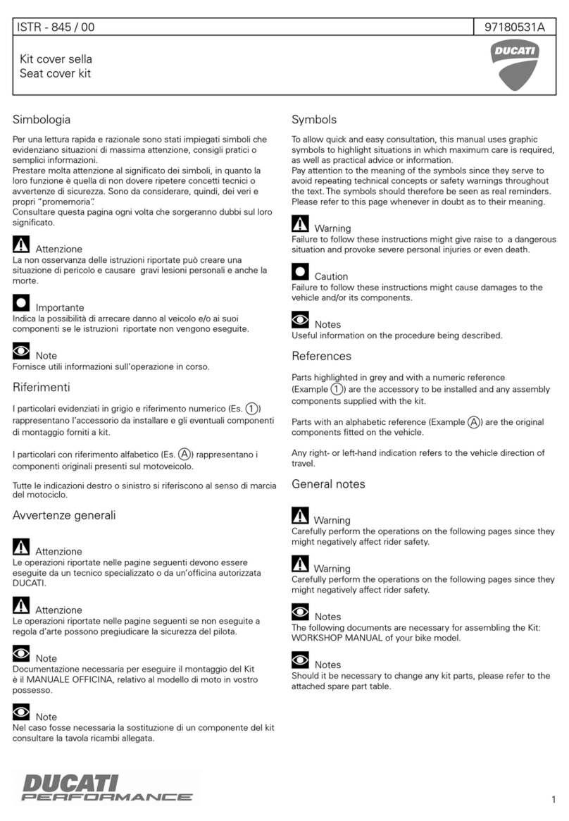
I particolari evidenziati in grigio e riferimento numerico (Es. ) rappresentano l’accessorio da
installare e gli eventuali componenti di montaggio forniti a kit. I particolari con riferimento
alfabetico (Es. ) rappresentano i componenti originali presenti sul motoveicolo.
Per una lettura rapida e razionale sono stati impiegati simboli che evidenziano situazioni di
massima attenzione, consigli pratici o semplici informazioni.
Tutte le indicazioni destro o sinistro si riferiscono al senso di marcia del motociclo.
Parts highlighted in grey and with a numeric reference (Example ) are the accessory to be
installed and any assembly components supplied with the kit. Parts with an alphabetic reference
(Example ) are the original components fitted on the vehicle.
For easy and rational reading, this document uses graphic symbols for
highlighting situations in which maximum care is required, practical advice or simple information.
Any right- or left-hand indication refers to the vehicle direction of travel.
Attenzione / Warning
La non osservanza delle istruzioni riportate può creare una situazione di pericolo e causare
gravi lesioni personali e anche la morte. / Failure to follow these instructions might give raise to
a dangerous situation and provoke severe personal injuries or even death.
Importante / Caution
Indica la possibilità di arrecare danno al veicolo e/o ai suoi componenti se le istruzioni
riportate non vengono eseguite. / Failure to follow these instructions might cause damages to the
vehicle and/or its components.
Note / Note
Fornisce utili informazioni sull'operazione in corso. / Useful information on the procedure
being described.
2
A
2
A
Monster 1200
Kit portatarga omologato sotto sella / Kit of type-approved underseat number plate holder - 97380141A
1 Gommino (q.tà 4)
2 Vite TCEIR M6x16 (q.tà 8)
3 Base portatarga
4 Passacavo
5 Braccio portatarga
6 Fermacavo (q.tà 3)
7 Fascetta (q.tà 2)
8 Boccola (q.tà 4)
9 Staffa inferiore
1 Grommet (q.ty 4)
2 TCEIR screw M6x16 (q.ty 8)
3 Number plate holder base
4Cablering
5 Number plate holder arm
6 Cable retainer (q.ty 3)
7 Tie (q.ty 2)
8 Bushing (q.ty 4)
9 Lower bracket
1
1
2
3
5
8
8
9
8
8
2
2
6
7
4
2
Pag. - Page 2/16 Cod. ISTR - 581 ED./ED. 00
10 Self-tapping M6 nut (q.ty 8)
11 Crown ring (q.ty 6)
12 Plate (q.ty 2)
13 TBEI screw M5x12 (q.ty 2)
14 TSPEI screw M5x10 (q.ty 2)
15 TSPEI screw M5x30 (q.ty 2)
16 Number plate holder plate (EU)
17 Number plate light spacer
18 Number plate light
19 TSPEI screw M6x14 (q.ty 4)
20 Bracket
21 Turn indicator wiring (q.ty 2)
22 Number plate light wiring
23 Central cat's eye retaining plate
24 Cat's eye (q.ty 3)
25 Lateral cat's eye retaining plate (q.ty 2)
26 TCEIF screw M5x50 (q.ty 2)
27 RH spacer
28 LH spacer
29 TCEIF screw M8x20 (q.ty 2)
30 Turn indicator support bracket (q.ty 2)
31 Self-tapping M8 nut (q.ty 2)
32 Turn indicator wiring
(q.ty 2)
33 Number plate holder plate (US)
34 Female connector plug
35 Male connector plug
10
2021
28
21
22
12
26
13
21
21
13
14
15 16 17
18
34 35
34 35
19
18
19
19
32
32
24
26
12
12
33
17
12 27
10 2411
1124 22
11 25
11
11
25
10
10
10
10
10 23
11
14
15
31
30 29
31
30
10 Dado autofrenante M6 (q.tà 8)
11 Anello a corona (q.tà 6)
12 Piastrino (q.tà 2)
13 Vite TBEI M5x12 (q.tà 2)
14 Vite TSPEI M5x10 (q.tà 2)
15 Vite TSPEI M5x30 (q.tà 2)
16 Piatto portatarga (EU)
17 Distanziale luce targa
18 Luce targa
19 Vite TSPEI M6x14 (q.tà 4)
20 Staffa
21 Cablaggio indicatori di direzione (q.tà 2)
22 Cablaggio luce targa
23 Piastrino fissaggio catadiottro centrale
24 Catadiottro (q.tà 3)
25 Piastrino fissaggio catadiottro laterale
(q.tà 2)
26 Vite TCEIF M5x50 (q.tà 2)
27 Distanziale destro
28 Distanziale sinistro
29 Vite TCEIF M8x20 (q.tà 2)
30 Staffa supporto indicatore (q.tà 2)
31 Dado autofrenante M8 (q.tà 2)
32 Cablaggio indicatore di direzione
(q.tà 2)
33 Piatto portatarga (US)
34 Tappo connettore femmina
35 Tappo connettore maschio
Pag. - Page 3/16Cod. ISTR - 581 ED./ED. 00
Pag. - Page 4/16 Cod. ISTR - 581 ED./ED. 00
Note
Read the instructions on the first
page carefully before proceeding.
Warning
Have the kit installed by a trained
technician or at a DUCATI Authorized
Workshop.
Removing the original
components
Warning
Incorrect installation of this kit may
put the rider’s safety at risk.
Note
The following documents are
necessary for assembling the Kit:
WORKSHOP MANUAL of your bike model
(Monster 1200).
Note
The number plate holder plate
changes according to the sales market, but
the removal stages do not change.
The European standard version removal
procedure is taken as a general example.
Remove silencer (G) as specified in
"Removing the silencer".
Remove rear wheel (H) as specified in
"Removing the rear wheel".
Removing the number plate holder unit
Unscrew no. 4 screws (D1) holding no. 4
nuts (D2), on the opposite side, and remove
the number plate (D).
Collect and keep screws (D1) and nuts (D2).
Disconnect connector (A1) of number plate
light from the relevant wiring (A2).
Remove number plate holder unit (A)
unscrewing no. 3 screws (A2).
Collect and keep the screws (A2).
Loosen the 2 nuts (A3) to remove the rear
cat's eye (A4).
H G
C
A
A2
D
D1
D2 A3 A4
A1 A2
Note
Prima di iniziare l’operazione, leggere
attentamente le avvertenze riportate nella
prima pagina.
Attenzione
Le operazioni di seguito riportate
devono essere eseguite da un tecnico
specializzato o da un’officina autorizzata
DUCATI.
Smontaggio componenti
originali
Attenzione
Le operazioni di seguito riportate se
non eseguite a regola d’arte possono
pregiudicare la sicurezza del pilota.
Note
Documentazione necessaria per
eseguire il montaggio del Kit è il: MANUALE
OFFICINA, relativo al modello di moto in
vostro possesso (Monster 1200).
Note
Il piatto portatarga varia a seconda del
mercato di vendita del motoveicolo, ma le
fasi di smontaggio non variano.
Come esempio viene presa la procedura di
smontaggio della versione standard
europea.
Rimuovere il silenziatore (G) seguendo
quanto riportato al capitolo "Smontaggio
silenziatore".
Rimuovere la ruota posteriore (H) seguendo
quanto riportato al capitolo "Smontaggio
ruota posteriore".
Smontaggio gruppo portatarga
Svitare le n.4 viti (D1) mantenendo, dalla
parte opposta, i n.4 dadi (D2) e rimuovere la
targa (D).
Recuperare e conservare le viti (D1) e i dadi
(D2).
Scollegare il connettore (A1) della luce targa
dal cablaggio luce targa (A2).
Rimuovere il gruppo portatarga (A) svitando
le n.3 viti (A2).
Recuperare e conservare le viti (A2).
Smontare il catadiottro posteriore (A4)
svitando i n,2 dadi (A3).
Pag. - Page 5/16Cod. ISTR - 581 ED./ED. 00
Remove seat (B) following the indications in
chapter "Removing the seat".
Remove tank (R) as specified in "Removing
the Fuel Tank".
Follow the instructions in chapter
"Removing the seat opening device" to
remove the opening device from the seat
bottom cover (E).
Loosen and collect the 2 screws (E1).
Follow the instructions in chapter
"Removing the rear grabhandles" to remove
the rear LH (M) and RH (N) grabhandle unit.
Follow the instructions provided in the
following page to disconnect the wiring
from the LH (M1) and RH (N1) turn
indicators.
Remove the seat bottom cover (E).
B R
E
F
M
N
M1
N1
E1
Rimuovere la sella (B) seguendo quanto
riportato al capitolo "Smontaggio sella".
Rimuovere il serbatoio (R) seguendo quanto
riportato al capitolo "Smontaggio serbatoio
carburante".
Rimuovere il dispositivo apertura sella dalla
cover fondo sella (E) seguendo quanto
riportato al capitolo "Smontaggio dispositivo
apertura sella".
Svitare e recuperare le n.2 viti (E1).
Smontare il gruppo maniglia posteriore
sinistra (M) e destra (N) seguendo quanto
riportato al capitolo "Smontaggio maniglie
posteriori".
Per scollegare i cablaggi della freccia
sinistra (M1) e freccia destra (N1) vedere
quanto riportato alla pagina seguente.
Rimuovere la cover fondo sella (E).
Pag. - Page 6/16 Cod. ISTR - 581 ED./ED. 00
CC1S1S
T
T1
U1
N3 U2
M3
U3
T2
M2N2
Pag. - Page 7/16Cod. ISTR - 581 ED./ED. 00
Disconnect pin (C1) of number plate light wiring (C) from socket (S1)
of the main wiring (S), as indicated in figure (X).
Cut tie (U3) that fastens the wiring of turn indicators (M3) and (N3)
with the rear wiring (T).
Disconnect pins (T1) and (T2) of the rear wiring (T) from sockets (M2)
and (N2) of the turn indicator wirings.
Cut ties (U1) and (U2).
Scollegare la spina (C1) del cablaggio luce targa (C) dalla presa (S1) del
cablaggio principale (S), come indicato in figura (X).
Tagliare le fascetta (U3) che raggruppa i cablaggi degli indicatori di
direzione (M3) ed (N3) con quello posteriore (T).
Scollegare le spine (T1) e (T2) del cablaggio posteriore (T) dalle prese
(M2) e (N2) dei cablaggi degli indicatori di direzione.
Tagliare le fascette (U1) ed (U2).
Pag. - Page 8/16 Cod. ISTR - 581 ED./ED. 00
Kit installation
Caution
Check that all components are clean
and in perfect condition before installation.
Adopt any precaution necessary to avoid
damages to any part of the motorcycle you
are working on.
Fit 4 grommets on the number plate holder
base (3) using soapy water.
Pay attention not to damage grommets (3).
Place number plate holder arm (5) by
matching the holes on the number plate
holder base (3) and start 4 screws (2).
Tighten no. 4 screws (2) to a torque of 10
Nm ± 10%.
Fit 4 bushings (8) on 4 screws (2).
Place the lower bracket (9) by matching the
holes on the number plate holder arm (5)
and start 4 screws (2) with bushings (8).
Tighten no. 4 screws (2) to a torque of 10
Nm ± 10%.
Fit cable ring (4) on number plate holder (3)
as shown in the figure.
Use alcohol or other oil-free detergents to
clean and degrease the surface where to fit
cable retainers (6).
Remove the film from the lower side of
cable retainers (6).
Position 2 cable retainers (6) on number
plate holder arm (5) as shown in the figure
and press to make the adhesive adhere.
Fit 2 ties (7) on lower bracket (9) as shown
in the figure.
1
1
2
3
5
8
8
9
7
7
6
3
9
6
4
5
8
8
2
2
2
Montaggio componenti kit
Importante
Verificare, prima del montaggio, che
tutti i componenti risultino puliti e in
perfetto stato. Adottare tutte le precauzioni
necessarie per evitare di danneggiare
qualsiasi parte nella quale ci si trova ad
operare.
Montare i n.4 gommini sulla base portatarga
(3) facendo uso di acqua saponata.
Prestare attenzione a non lacerare i
gommini (3).
Posizionare il braccio portatarga (5), facendo
corrispondere le forature, sulla base
portatarga (3) e impuntare le n.4 viti (2).
Serrare le n.4 viti (2) alla coppia di 10 Nm ±
10%.
Inserire le n.4 boccole (8) sulle n.4 viti (2).
Posizionare la staffa inferiore (9), facendo
corrispondere le forature, sul braccio
portatarga (5) e impuntare le n.4 viti (2) con
boccole (8).
Serrare le n.4 viti (2) alla coppia di 10 Nm ±
10%.
Montare il passacavo (4) sulla base
portatarga (3), come indicato in figura.
Pulire e sgrassare la superficie dove si
devono applicare i fermacavi (6), con alcool
o altro detergente non grasso.
Rimuovere la pellicola dale parte inferiore
dei fermacavi (6).
Posizionare i n.2 fermacavi (6) sul braccio
portatarga (5) come indicato in figura e
premere con forza per fare aderire l'adesivo.
Montare le n.2 fascette (7) sulla staffa
inferiore (9), come indicato in figura.
Pag. - Page 9/16Cod. ISTR - 581 ED./ED. 00
Number plate holder plate
assembly (EU version)
Insert wiring (18A) of number plate light (18)
inside spacer (17).
Position spacer (17) and number plate light
(18) on number plate holder plate (16) by
routing wiring (18A) inside the suitable hole
on the number plate holder and start 2
screws (15).
Tighten 2 screws (15) to a torque of 6 Nm ±
10%.
Insert wiring (M2) in the LH spacer (28)
through slot (28A); slide the original turn
indicator (M1) fully against spacer (28)
without pulling the wiring too much. .
Note
The LH (28) and RH (27) spacers must
be oriented with slots (28A) facing
downwards.
osition the LH turn indicator with the
relevant spacer on the number plate holder
plate (16) by routing wiring (M2) in the
suitable slot; on the opposite side, position
plate (12) and fix it by tightening screw (26)
to a torque of 3 Nm ± 10%.
Repeat the same operation to fix the
original RH turn indicator (N1) using the RH
spacer (27).
Insert number plate light wiring (18A) inside
slot (5A).
Position the number plate holder unit (16)
on the lower bracket (9), start 2 screws (19)
and on the other side tighten nuts (10) to a
torque of 10 Nm ± 10%.
Pre-fit the rear original cat's eye (A4) on
bracket (20) by tightening 2 original nuts
(A3) to a torque of 2 Nm ± 10%.
Position number plate (D) on the relevant
holder unit (16), start 2 original screws (D1)
in the upper holes and on the internal side
screw 2 original nuts (D2).
Position the just fitted cat's eye unit in the
lower holes of the number plate holder
plate (16) working from the internal side;
start 2 original screws (D1) and screw 2
original nuts (D2) from the internal side.
17
18
15
18A
18A
9
5A
10
19
1916
20D2
D1
D
A4
A3
12
26
28 28A
26 12 N127
16
M1
M2
N2
Montaggio piatto portatarga
(versione EU)
Far scorrere il cablaggio (18A) della luce
targa (18) all'interno del distanziale (17).
Posizionare sul piatto portatarga (16) il
distanziale (17) e la luce targa (18) facendo
passare il cablaggio (18A) nell'apposita
foratura sul portatarga e impuntare le n.2 viti
(15).
Serrare le n.2 viti (15) alla coppia di 6 Nm ±
10%.
Inserire il cablaggio (M2) nel distanziale
sinistro (28) attraverso la fessura (28A); far
scorrere l'indicatore di direzione originale
(M1) fino a battuta con il distanziale (28)
senza tirare eccessivamente il cablaggio.
Note
I distanziali sinistro (28) e destro (27)
vanno orientati con le fessure (28A) rivolte
verso il basso.
Posizionare l'indicatore sinistro completo di
distanziale sul piatto portatarga (16) facendo
passare il cablaggio (M2) nell'apposita
foratura; dalla parte opposta posizionare il
piastrino (12) e fissare avvitando e serrando
la vite (26) alla coppia di 3 Nm ± 10%.
Ripetere la medesima operazione per
fissare l'indicatore di direzione destro
originale (N1), utilizzando il distanziale
destro (27).
Far scorrere il cablaggio (18A) della luce
targa all'interno dell'asolatura (5A).
Posizionare il gruppo piatto portatarga (16)
sulla staffa inferiore (9), impuntare le n.2 viti
(19) e dall'altro lato avvitare e serrare i dadi
(10) alla coppia di 10 Nm ± 10%.
Premontare il catadiottro posteriore
originale (A4) sulla staffa (20) avvitando e
serrando i n.2 dadi originali (A3) alla coppia
di 2 Nm ± 10%.
Posizionare la targa (D) sul gruppo piatto
portatarga (16), impuntare le n.2 viti originali
(D1) sui fori superiori e dal lato interno
avvitare n.2 dadi originali (D2).
Nei fori inferiori del piatto portatarga (16)
posizionare, dal lato interno, il gruppo
catadiottro posteriore appena premontato;
impuntare le n.2 viti originali (D1) e dal lato
interno avvitare n.2 dadi originali (D2).
Pag. - Page 10/16 Cod. ISTR - 581 ED./ED. 00
Number plate holder plate
assembly (US version)
Insert wiring (18A) of number plate light (18)
inside spacer (17).
Position spacer (17) and number plate light
(18) on number plate holder plate (33) by
routing wiring (18A) inside the suitable hole
on the number plate holder and start 2
screws (15).
Tighten 2 screws (15) to a torque of 6 Nm ±
10%.
Position the original LH turn indicator (M1)
on the number plate holder plate (33) by
routing wiring (M2) in the suitable slot; on
the opposite side, position plate (12) and fix
the turn indicator (M1) by tightening screw
(13) to a torque of 3 Nm ± 10%.
Repeat the same operation to fix the
original RH turn indicator (N1).
Pre-fit the central cat's eye (24) on plate (23)
and block it with 2 crown rings (11).
Pre-fit 2 lateral cat's eyes (24) on 2 lateral
retaining plates (25) and block them with 4
crown rings (11).
Insert number plate light wiring (18A) inside
slot (5A).
Position the number plate holder unit (33)
on the lower bracket (9) and start 2 screws
(19); on the other side, position the just
fitted central cat's eye unit on the screw
threads and tighten nuts (10) to a torque of
10 Nm ± 10%.
Position the pre-fitted lateral cat's eye units
on the number plate holder plate (33)
internal side by matching the holes and start
2 screws (19) in the upper holes.
Screw 2 nuts (10) on screw (19) threads to
a torque of 10 Nm ± 10%.
Position number plate (V) on the relevant
holder unit (33), start 4 original screws (V1)
and on the internal side screw 4 nuts (10).
12
13
13 12 N1
17
18
15
18A
18A23
33
M1 M2
N2
9
24
24 25
5A
11
10
10
33
19
VV1
2511
11
10
10
24
11
11
Montaggio piatto portatarga
(versione US)
Far scorrere il cablaggio (18A) della luce
targa (18) all’interno del distanziale (17).
Posizionare sul piatto portatarga (33) il
distanziale (17) e la luce targa (18) facendo
passare il cablaggio (18A) nell'apposita
foratura sul portatarga e impuntare le n.2 viti
(15).
Serrare le n.2 viti (15) alla coppia di 6 Nm ±
10%.
Posizionare l'indicatore di direzione sinistro
originale (M1) sul piatto portatarga (33)
facendo passare il cablaggio (M2)
nell’apposita foratura; dalla parte opposta
posizionare il piastrino (12) e fissare
l’indicatore (M1) avvitando e serrando la vite
(13) alla coppia di 3 Nm ± 10%.
Ripetere la medesima operazione per
fissare l'indicatore di direzione destro
originale (N1).
Premontare il catadiottro centrale (24) sul
piastrino (23) bloccandolo con n.2 anelli a
corona (11).
Premontare i n.2 catadiottri laterali (24) sui
n.2 piastrini di fissaggio laterali (25)
bloccandoli con n.4 anelli a corona (11).
Far scorrere il cablaggio (18A) della luce
targa all’interno dell’asolatura (5A).
Posizionare il gruppo piatto portatarga (33)
sulla staffa inferiore (9) e impuntare le n.2
viti (19); dall'altro lato posizionare sui filetti
delle viti il gruppo catadiottro centrale
appena premontato, avvitare e serrare i dadi
(10) alla coppia di 10 Nm ± 10%.
Posizionare i gruppi catadiottri laterali
premontati in precedenza nel lato interno
del piatto portatarga (33) facendo
corrispondere le forature e impuntare, nei
fori superiori, n.2 viti (19).
Avvitare sui filetti delle viti (19) n.2 dadi (10)
e serrare alla coppia di 10 Nm ± 10%.
Posizionare la targa (V) sul gruppo piatto
portatarga (33), impuntare le n.4 viti originali
(V1) e dal lato interno avvitare n.4 dadi (10).
Pag. - Page 11/16Cod. ISTR - 581 ED./ED. 00
Fitting the LED turn indicators.
It is possible to fit LED turn indicators (Z) on
the type-approved underseat number plate
holder kit by ordering the relevant kit with
part no. 96680231A.
Use no. 2 screws (29), no. 2 nuts (31) and
no. 2 support brackets (30) following the
sequence indicated in the figure.
31
29
31
Z
Z
30
30
16
Montaggio indicatori di direzione
a led
È possibile montare sul kit portatarga
omologato sotto sella gli indicatori a led (Z)
disponibili a kit ordinando il cod.
96680231A.
Utilizzare le n.2 viti (29), i n.2 dadi (31) e le
n.2 staffe di supporto (30) nella sequenza di
montaggio indicata in figura.
Pag. - Page 12/16 Cod. ISTR - 581 ED./ED. 00
22
21
21
32
32
Y
22
Y
C
CC234
W1
W2
2222A
W
W1
W
C1
35
Pag. - Page 13/16Cod. ISTR - 581 ED./ED. 00
Lay down the number plate light wiring (22) following the rear wiring
path (Y). To
fix the wiring use commercial self-locking ties.
Disconnect pin (C2) of the original number plate light wiring (C) from
socket (W1) of the main wiring (W).
To protect the contacts of the original number plate light extension
(C) use female plug (34) on pin (C2) and tie it to the main wiring using
the original rubber clamp (W2); on the opposite side of wiring (C) use
the male plug (35) on socket (C1).
Connect socket (22A) of the number plate light wiring (22) to socket
(W1) of the main wiring (W).
Connect 2 wirings of turn indicators (21) to the rear wiring (Y).
Note
When fitting the LED turn indicator kit part no. 96680231A, it is
necessary to connect 2 wirings (32) to the rear wiring (Y).
Distendere il cablaggio luce targa (22) seguendo il percorso del
cablaggio posteriore (Y). Per il
fissaggio, utilizzare fascette a strappo di tipo commerciale.
Scollegare la spina (C2) del cablaggio luce targa originale (C) dalla
presa (W1) del cablaggio principale (W).
Per proteggere i contatti della prolunga luce targa originale (C)
utilizzare il tappo femmina (34) sulla spina (C2) e fascettarlo al
cablaggio principale utilizzando la fascetta in gomma originale (W2);
dalla parte opposta del cablaggio (C) utilizzare il tappo maschio (35)
sulla presa (C1).
Collegare la presa (22A) del cablaggio luce targa (22) alla presa (W1)
del cablaggio principale (W).
Collegare i n.2 cablaggi indicatori di direzione (21) al cablaggio
posteriore (Y).
Note
Nel caso in cui venga montato il kit indicatori di direzione a led
con cod. 96680231A, occorre collegare i n. 2 cablaggi (32) al
cablaggio posteriore (Y).
Pag. - Page 14/16 Cod. ISTR - 581 ED./ED. 00
Lay down the wiring of the LH (M2) and RH
(N2) original turn indicators as shown in the
figure.
To fix the wiring use 2 ties (7), 2 cable
retainers (6) and cable ring (4), as shown in
the figure.
Fix the number plate light wiring (18A) to
one of the 2 ties (7), as shown in the figure.
Position the original seat bottom cover (E)
on the rear subframe, having care that the
wirings of turn indicators (21) and number
plate light (22) are outside the cover.
On the upper side, fix the seat bottom cover
(E) by starting 2 original screws (E1).
Tighten 2 screws (E1) to a torque of 3 Nm ±
10%.
Position the rear RH (N3) and LH (M3)
grabhandles and fix them
to the subframe by starting 2 original special
screws (AA) in the front holes.
Start no. 2 original special screws (BB) in
the rear holes of grabhandles (N3) and (M3)
by fixing both the grabhandles and the seat
bottom cover (E).
Tighten the no. 2 special screws (AA) and
no. 2 special screws (BB) to a torque of 20
Nm ± 10%.
Follow the instructions in chapter "Refitting
the seat opening device" to fit the opening
device on the seat bottom cover (E).
7
7
6
6
18A
4
M2 N2
E21
21
22
FM3
N3
AA
AA
BB
BB
E1
Distendere il cablaggio indicatore di
direzione sinistro originale (M2) e destro
(N2) come mostrato in figura.
Per il fissaggio utilizzare le n.2 fascette (7), i
n.2 fermacavi (6) e il passacavo (4), come
indicato in figura.
Fissare il cablaggio luce targa (18A) a una
delle n.2 fascette (7), come indicato in
figura.
Posizionare la cover fondo sella originale (E)
sul telaietto posteriore, prestando
attenzione che i cablaggi degli indicatori di
direzione (21) e luce targa (22) siano
all'esterno della cover.
Sul lato superiore, fissare la cover fondo
sella (E) impuntando le n.2 viti originali (E1).
Serrare le n.2 viti (E1) alla coppia di 3 Nm ±
10%.
Posizionare il maniglione posteriore destro
(N3) ed il maniglione posteriore sinistro
(M3) e fissarli
al telaietto impuntando le n.2 viti speciali
originali (AA) in corrispondenza dei fori
anteriori.
Impuntare le n.2 viti speciali originali (BB) in
corrispondenza dei fori posteriori dei
maniglioni (N3) e (M3), fissando sia i
maniglioni che la cover fondo sella (E).
Serrare le n. 2 viti speciali (AA) e le n. 2 viti
speciali (BB) alla coppia di 20 Nm ± 10%.
Rimontare il dispositivo apertura sella sulla
cover fondo sella (E) seguendo quanto
riportato al capitolo "Rimontaggio
dispositivo apertura sella".
Pag. - Page 15/16Cod. ISTR - 581 ED./ED. 00
Route the number plate holder wiring (22)
inside number plate holder base (3) by
sliding it next to the RH turn indicator wiring
(N2), as shown in the figure.
Connect number plate light pin (18A) to the
number plate light wiring socket (22) and fix
it inside the number plate holder arm (5).
Connect the wiring sockets of the LH (M2)
and RH (N2) turn indicators to the pins of
the 2 extensions (21).
Position the just connected wirings in the
relevant seats (3A) and (3B).
Position the underseat number plate holder
unit by matching the holes and start 4
original screws (CC).
Gather the exceeding part of the cable
inside the rear subframe.
Tighten 4 screws (CC) to a torque of
8 Nm ± 10%.
CC
N2
21
22
18A
M2
3A
3B
CC
3
5
Far passare il cablaggio luce targa (22)
all'interno della base portatarga (3)
facendolo scorrere a fianco del cablaggio
indicatore destro (N2), come mostrato in
figura.
Collegare la spina (18A) della luce targa alla
presa del cablaggio luce targa (22) e fissarlo
all'interno del braccio portatarga (5).
Collegare le prese dei cablaggi indicatore
sinistro (M2) e destro (N2) alle spine delle
n.2 prolunghe (21).
Posizionare i cablaggi appena collegati nelle
apposite sedi (3A) e (3B).
Posizionare il gruppo portatarga sottosella
facendo corrispondere le forature e
impuntare n.4 viti originali (CC).
Raccogliere tutte le eccedenze di cavo
all'interno del telaietto posteriore.
Serrare le n. 4 viti (CC) alla coppia di
8 Nm ± 10%.
Pag. - Page 16/16Cod. ISTR - 581 ED./ED. 00
Fitting the "short" number plate
holder
Caution
It is possible to use the "short"
underseat number plate holder in those
countries whose road traffic laws allow it. It
is possible to use the "short" underseat
number plate holder in private facilities or
facilities arranged as a track.
Position number plate light (18) on number
plate holder plate (16) by routing the wiring
inside the suitable hole on the number plate
holder and start 2 screws (14). Tighten 2
screws (14) to a torque of 6 Nm ± 10%.
Position the original LH turn indicator (M1)
on the number plate holder plate (16) by
routing wiring (M2) in the suitable slot; on
the opposite side, position plate (12) and fix
the turn indicator (M1) by tightening screw
(13) to a torque of 3 Nm ± 10%.
Repeat the same operation to fix the
original RH turn indicator (N1).
Position the number plate holder unit (16)
on the number plate holder base (3), start 4
screws (2) and tighten to a torque of 10 Nm
± 10%.
The fitting procedure of the number plate
holder unit on the motorcycle and the
consequent wiring connection remains
unchanged. Gather the exceeding part of
the cable inside the rear subframe.
It is possible to fit LED turn indicators (Z) on
the "short" number plate holder by ordering
the relevant kit with part no. 96680231A, as
shown in the figure. The correct fitting
sequence is specified in the assembly
instructions provided with the kit.
Refit tank (R) as specified in chapter
"Refitting the fuel tank".
Reassemble seat (B) following the
indications in chapter "Refitting the seat".
Refit rear wheel (H) as specified in "Refitting
the rear wheel". Refit silencer (G) as
specified in "Refitting the silencer".
Check
Check for rear lights correct operation. In
particular:
- LH turn indicator
- RH turn indicator
- Number plate light
In case of incorrect operation, make sure
that plugs and sockets are properly
connected, as well as that wiring cables are
properly coupled.
H G
B R
2
3
2
14
16
18
12
12
Z
Z
13
13
N1
M1 M2
Montaggio portatarga in
configurazione corta
Importante
E' possibile utilizzare il portatarga
sottosella, in configurazione corta, nei paesi
in cui le leggi che regolano la circolazione
stradale lo consentano. E' possibile
utilizzare il portatarga sottosella in
configurazione corta in strutture private o
adibite a pista.
Posizionare sul piatto portatarga (16) la luce
targa (18) facendo passare il cablaggio
nell'apposita foratura sul portatarga e
impuntare le n.2 viti (14). Serrare le n.2 viti
(14) alla coppia di 6 Nm ± 10%.
Posizionare l'indicatore di direzione sinistro
originale (M1) sul piatto portatarga (16)
facendo passare il cablaggio (M2)
nell'apposita foratura; dalla parte opposta
posizionare il piastrino (12) e fissare
l'indicatore (M1) avvitando e serrando la vite
(13) alla coppia di 3 Nm ± 10%.
Ripetere la medesima operazione per
fissare l'indicatore di direzione destro
originale (N1).
Posizionare il gruppo piatto portatarga (16)
sulla base portatarga (3), impuntare le n.4
viti (2) e serrare alla coppia di 10 Nm ± 10%.
Il montaggio del gruppo portatarga sul
motoveicolo e il conseguente collegamento
dei cablaggi rimane il medesimo
raccogliendo tutte le eccedenze di cavo
all'interno del telaietto posteriore.
È possibile montare sul portatarga in
configurazione corta gli indicatori a led (Z)
disponibili a kit ordinando il cod.
96680231A, come indicato in figura. La
corretta sequenza di montaggio viene
riportata nell'istruzione di montaggio
allegata al kit stesso.
Rimontare il serbatoio (R) seguendo quanto
riportato al capitolo "Rimontaggio serbatoio
carburante".
Rimontare la sella (B) seguendo quanto
riportato al capitolo "Rimontaggio sella".
Rimontare la ruota posteriore (H) seguendo
quanto riportato al capitolo "Rimontaggio
ruota posteriore". Rimontare il silenziatore
(G) seguendo quanto riportato al capitolo
"Rimontaggio silenziatore".
Verifica
Controllare l'effettivo funzionamento dei
dispositivi ottici posteriori:
- Indicatore di direzione sinistro
- Indicatore di direzione destro
-Lucetarga
In caso di malfunzionamento verificare il
corretto fissaggio delle prese con le spine e
l'abbinamento giusto dei rami del cablaggio.
Modèles de référence: / Bezugsmodelle:
Les pièces surlignées en gris et la référence numérique (Ex. ) représentent l'accessoire à
installer et les composants de montage éventuels fournis en kit. Les pièces avec référence
alphabétique (Ex. ) représentent les composants d'origine présents sur le motocycle.
Pour une lecture rapide et rationnelle ont été utilisés des symboles qui mettent en évidence les
situations exigeant une attention particulière, les conseils pratiques ou bien encore de simples
informations. Toutes les indications droite ou gauche se réfèrent au sens de marche la moto.
Die grau gekennzeichneten Bestandteile mit numerischem Bezug (Bsp. ) geben das zu
installierende Bestandteil und die eventuellen, im Kit enthaltenen Montagekomponenten wieder.
Die Bestandteile mit alphabetischem Bezug (Bsp. ) geben die Original-Bestandteile wieder,
die am Motorrad verbaut wurden. Im Sinne einer schnellen und rationellen Erfassung beim Lesen
wurden Symbole verwendet, die auf Situationen hinweisen, bei denen maximale
Aufmerksamkeit geboten ist, oder die praktische Empfehlungen bzw. einfache Informationen
hervorheben. Alle Angaben wie „rechts” oder „links” beziehen sich auf die Fahrtrichtung des
Motorrads.
Attention / Achtung
La non-observance des instructions reportées ci-dessous peut créer une situation
dangereuse et provoquer de graves lésions personnelles voire la mort. / Eine Nichtbeachtung der
hier wiedergegebenen Anweisungen kann Gefahrensituationen schaffen und zu schweren
Verletzungen und auch zum Tod führen.
Important / Wichtig
Indique la possibilité d'endommager le véhicule et/ou ses composants si les instructions
reportées ci-dessous ne sont pas suivies. / Weist darauf hin, dass bei Nichteinhaltung der hier
wiedergegebenen Anweisungen die Möglichkeit für Schäden am Fahrzeug und/oder seiner
Komponenten besteht.
Remarques / Hinweis
Fournit des informations utiles sur l'opération en cours. / Übermittelt nützliche
Informationen zum betreffenden Arbeitseingriff.
2
A
2
A
Code. ISTR / Art.-Nr. ANLEIT - 581 Page - Seite 1/16
ISTR/ANLEIT - 581 ED./AUSG. 00
ED./AUSG. 00
Monster 1200
Kit support de plaque d'immatriculation homologué dessous-de-selle /
Kit zugelassener Kennzeichenhalter unter Sitzbank - 97380141A
1 Plot caoutchouc (q.té 4)
2 Vis TCHCF M6x16 (q.té 8)
3 Base support de plaque
d'immatriculation
4 Passe-fil
5 Bras support de plaque
d'immatriculation
6 Arrêtoir de câble (q.té 3)
7 Collier serre-flex (q.té 2)
8 Bague (q.té 4)
9 Bride inférieure
1 Gummielement (4 Stck.)
2 Spezialinnensechskantschraube
M6x16 (8 Stck.)
3 Unterlage für Kennzeichenhalter
4 Kabelführung
5 Kennzeichenhalterarm
6 Kabelhalter (3 Stck.)
7 Schelle (2 Stck.)
8 Buchse (4 Stck.)
9 Unterer Bügel
1
1
2
3
5
8
8
9
8
8
2
2
6
7
4
2
Page - Seite 2/16 Code. ISTR / Art.-Nr. ANLEIT - 581 ED./AUSG. 00
10 Selbstsicherende Mutter M6 (8 Stck.)
11 Zahnring (6 Stck.)
12 Plättchen (2 Stck.)
13 Linseninnensechskantschraube M5x12
(2 Stck.)
14 Spezialinnensechskantschraube
M5x10 (2 Stck.)
15 Spezialinnensechskantschraube
M5x30 (2 Stck.)
16 Kennzeichenhalterplatte (EU)
17 Distanzstück für Kennzeichenbeleuchtung
18 Kennzeichenbeleuchtung
19 Spezialinnensechskantschraube
M6x14 (4 Stck.)
20 Bügel
21 Blinkerverkabelung (2 Stck.)
22 Verkabelung für
Kennzeichenbeleuchtung
23 Befestigungsplättchen für mittleren
Rückstrahler
24 Rückstrahler (3 Stck.)
25 Befestigungsplättchen für seitlichen
Rückstrahler (2 Stck.)
26 Geflanschte Innensechskantschraube
M5x50 (2 Stck.)
27 Rechtes Distanzstück
28 Linkes Distanzstück
29 Geflanschte Innensechskantschraube
M8x20 (2 Stck.)
30 Blinkerhaltebügel (2 Stck.)
31 Selbstsicherende Mutter M8 (2 Stck.)
32 Blinkerverkabelung (2 Stck.)
33 Kennzeichenhalterplatte (US)
34 Steckerverschlusskappe
35 Steckerverschlusseinsatz
10
2021
28
21
22
12
26
13
21
21
13
14
15 16 17
18
34 35
34 35
19
18
19
19
32
32
24
26
12
12
33
17
12 27
10 2411
1124 22
11 25
11
11
25
10
10
10
10
10 23
11
14
15
31
30 29
31
30
10 Écrou autofreiné M6 (q.té 8)
11 Bague à couronne (q.té 6)
12 Plaquette (q.té 2)
13 Vis TBHC M5x12 (q.té 2)
14 Vis TFPHC M5x10 (q.té 2)
15 Vis TFPHC M5x30 (q.té 2)
16 Porte-plaque d'immatriculation (EU)
17 Entretoise éclairage plaque
d'immatriculation
18 Éclairage plaque d'immatriculation
19 Vis TFPHC M6x14 (q.té 4)
20 Bride
21 Câblage clignotants (q.té 2)
22 Câblage éclairage plaque
d'immatriculation
23 Plaquette de fixation catadioptre
central
24 Catadioptre (q.té 3)
25 Plaquette de fixation catadioptre latéral
(q.té 2)
26 Vis TCHC M5x50 (q.té 2)
27 Entretoise droite
28 Entretoise gauche
29 Vis TCHC M8x20 (q.té 2)
30 Bride de support clignotant (q.té 2)
31 Écrou autofreiné M8 (q.té 2)
32 Câblage clignotant
(q.té 2)
33 Porte-plaque d'immatriculation (US)
34 Bouchon connecteur femelle
35 Bouchon connecteur mâle
Page - Seite 3/16Code. ISTR / Art.-Nr. ANLEIT - 581 ED./AUSG. 00
Page - Seite 4/16 Code. ISTR / Art.-Nr. ANLEIT - 581 ED./AUSG. 00
Hinweis
Vor Beginn der Arbeitseingriffe die
Warnhinweise auf der ersten Seite auf-
merksam durchlesen.
Achtung
Die nachstehend beschriebenen Ar-
beitseingriffe müssen von einem Fachtech-
niker oder einer DUCATI Vertragswerkstatt
ausgeübt werden.
Abnahme der Original-Teile
Achtung
Folgende Arbeitseingriffe können,
falls nicht fachgerecht ausgeübt, die
Sicherheit des Fahrers gefährden.
Hinweis
Für die Montage des Kits sind
folgende Unterlagen erforderlich:
WERKSTATT-HANDBUCH, des sich in
Ihrem Besitz befindlichen Motorrads
(Monster 1200).
Hinweis
Die Kennzeichenhalterplatte fällt in
Abhängigkeit des jeweiligen Absatzmarkts
des Motorrads unterschiedlich aus, die
Abnahmphasen sind jedoch identisch.
Als Beispiel wird das Abnahmeverfahren
der Standard-Version Europa
herangezogen.
Den Schalldämpfer (G) den Angaben im
Kapitel „Abnahme des Schalldämpfers”
gemäß abnehmen.
Das Hinterrad (H) den Angaben im Kapitel
„Abnahme des Hinterrads” gemäß
entfernen.
Abnahme der
Kennzeichenhaltereinheit
Die 4 Schrauben (D1) lösen und dabei an der
gegenüberliegenden Seite die 4 Muttern
(D2) gegenhalten, dann das Kennzeichen
(D) abnehmen.
Die Schrauben (D1) und die Muttern (D2)
aufnehmen und aufbewahren.
Den Verbinder (A1) der
Kennzeichenbeleuchtung von der
Verkabelung der Kennzeichenbeleuchtung
(A2) trennen.
Die Kennzeichenhaltereinheit (A) nach dem
Lösen der 3 Schrauben (A2) entfernen.
Die Schrauben (A2) aufnehmen und
aufbewahren.
Den hinteren Rückstrahler (A4) nach dem
Lösen der 2 Muttern (A3) abnehmen.
H G
C
A
A2
D
D1
D2 A3 A4
A1 A2
Remarques
Avant de commencer l’opération, lire
attentivement les avertissements reportés
sur la première page.
Attention
Les opérations reportées ci-après doi-
vent être effectuées par un technicien spé-
cialisé ou par un atelier agréé DUCATI.
Dépose composants d'origine
Attention
Une mauvaise exécution des
opérations ci-dessous peut préjudicier à la
sécurité du pilote.
Remarques
La documentation nécessaire pour
effectuer la pose du Kit est le : MANUEL
D'ATELIER, relatif au modèle de moto en
votre possession (Monster 1200).
Remarques
Le porte-plaque d'immatriculation
diffère selon le marché de vente du
motocycle, mais les phases de dépose
restent inchangées.
On considère la procédure de dépose de la
version standard européenne comme
exemple.
Déposer le silencieux (G) en suivant la
procédure indiquée au chapitre « Dépose
silencieux ».
Déposer la roue arrière (H) en suivant les
instructions indiquées au chapitre « Dépose
roue arrière ».
Dépose ensemble support de plaque
d'immatriculation
Desserrer le 4 vis (D1) en gardant, du côté
opposé, les 4 écrous (D2) et déposer la
plaque d'immatriculation (D).
Récupérer et conserver les vis (D1) et les
écrous (D2).
Débrancher le connecteur (A1) de
l'éclairage plaque d'immatriculation du
câblage éclairage plaque d'immatriculation
(A2).
Déposer l'ensemble support de plaque
d'immatriculation (A) en desserrant les 3 vis
(A2).
Récupérer et conserver les vis (A2).
Déposer le catadioptre arrière (A4) en
desserrant les 2 écrous (A3).

Other Ducati Motorcycle Accessories manuals

Ducati 96781131A User manual

Ducati

Ducati 96781131A User manual

Ducati Performance 97380261A User manual

Ducati

Ducati Performance 97380261A User manual

Ducati 96980731A User manual

Ducati

Ducati 96980731A User manual

Ducati 96780311A User manual

Ducati

Ducati 96780311A User manual

Ducati 97180531A User manual

Ducati

Ducati 97180531A User manual

Ducati 96480931A User manual

Ducati

Ducati 96480931A User manual

Ducati 96981071A User manual

Ducati

Ducati 96981071A User manual

Ducati ISTR - 788 / 00 User manual

Ducati

Ducati ISTR - 788 / 00 User manual

Ducati 96780011A User manual

Ducati

Ducati 96780011A User manual

Ducati 97380331A User manual

Ducati

Ducati 97380331A User manual

Ducati 96380031A User manual

Ducati

Ducati 96380031A User manual

Ducati 96780111A User manual

Ducati

Ducati 96780111A User manual

Ducati Performance 97380071A User manual

Ducati

Ducati Performance 97380071A User manual

Ducati Performance 96780881A User manual

Ducati

Ducati Performance 96780881A User manual

Ducati KIT Top Case 1106 User manual

Ducati

Ducati KIT Top Case 1106 User manual

Ducati 96280541A User manual

Ducati

Ducati 96280541A User manual

Ducati 96680441A User manual

Ducati

Ducati 96680441A User manual

Ducati Multistrada 1200 User manual

Ducati

Ducati Multistrada 1200 User manual

Ducati 96680691A User manual

Ducati

Ducati 96680691A User manual

Ducati 97180741A User manual

Ducati

Ducati 97180741A User manual

Ducati 96780652A User manual

Ducati

Ducati 96780652A User manual

Ducati 96981061A User manual

Ducati

Ducati 96981061A User manual

Ducati SBK 1199 User manual

Ducati

Ducati SBK 1199 User manual

Ducati 96989981A User manual

Ducati

Ducati 96989981A User manual

Popular Motorcycle Accessories manuals by other brands

Sundstrom SR 592 Instructions for use

Sundstrom

Sundstrom SR 592 Instructions for use

Urrea USCS6 User manual and warranty

Urrea

Urrea USCS6 User manual and warranty

Jesse Luggage Slide Lock Plate install guide

Jesse Luggage

Jesse Luggage Slide Lock Plate install guide

KTM Power Parts Information

KTM

KTM Power Parts Information

AFX FX-76 INTERNATIONAL OWNER’S MANUAL

AFX

AFX FX-76 INTERNATIONAL OWNER’S MANUAL

SRC T-XRX-07-01-SL manual

SRC

SRC T-XRX-07-01-SL manual

C-RACER RH-KTM390-SB instructions

C-RACER

C-RACER RH-KTM390-SB instructions

NOOANCE M-120 manual

NOOANCE

NOOANCE M-120 manual

Triumph My Triumph Connectivity Owner's handbook

Triumph

Triumph My Triumph Connectivity Owner's handbook

kellermann Bullet 1000 Extreme installation manual

kellermann

kellermann Bullet 1000 Extreme installation manual

hepco & becker 630754 00 01 manual

hepco & becker

hepco & becker 630754 00 01 manual

hepco & becker 504674 00 01 quick start guide

hepco & becker

hepco & becker 504674 00 01 quick start guide

MSA GAA Series manual

MSA

MSA GAA Series manual

Livall Helmetphone RS1 quick start guide

Livall

Livall Helmetphone RS1 quick start guide

DYNATEK D3K1-2 installation instructions

DYNATEK

DYNATEK D3K1-2 installation instructions

DK Custom DK-SFT-M8-FLB-EXT instructions

DK Custom

DK Custom DK-SFT-M8-FLB-EXT instructions

SW-Motech ALU-RACK GPT.06.627.15000/B Mounting instructions

SW-Motech

SW-Motech ALU-RACK GPT.06.627.15000/B Mounting instructions

hepco & becker 6607562 01 01 manual

hepco & becker

hepco & becker 6607562 01 01 manual

manuals.online logo
manuals.online logoBrands
  • About & Mission
  • Contact us
  • Privacy Policy
  • Terms and Conditions

Copyright 2025 Manuals.Online. All Rights Reserved.