manuals.online logo
Brands
  1. Home
  2. •
  3. Brands
  4. •
  5. Ducati
  6. •
  7. Motorcycle Accessories
  8. •
  9. Ducati 96780011A User manual

Ducati 96780011A User manual

Modelli di riferimento: / Reference Ducati Motorcycles:
Cod. ISTR - 508 Pag. - Page 1/17ED./ED. 01
ISTR - 508 ED./ED. 01
I particolari evidenziati in grigio e riferimento numerico (Es. ) rappresentano l’accessorio da
installare e gli eventuali componenti di montaggio forniti a kit. I particolari con riferimento
alfabetico (Es. ) rappresentano i componenti originali presenti sul motoveicolo.
Per una lettura rapida e razionale sono stati impiegati simboli che evidenziano situazioni di
massima attenzione, consigli pratici o semplici informazioni.
Tutte le indicazioni destro o sinistro si riferiscono al senso di marcia del motociclo.
Parts highlighted in grey and with a numeric reference (Example ) are the accessory to be
installed and any assembly components supplied with the kit. Parts with an alphabetic reference
(Example ) are the original components fitted on the vehicle.
For easy and rational reading, this document uses graphic symbols for
highlighting situations in which maximum care is required, practical advice or simple information.
Any right- or left-hand indication refers to the vehicle direction of travel.
Attenzione / Warning
La non osservanza delle istruzioni riportate può creare una situazione di pericolo e causare
gravi lesioni personali e anche la morte. / Failure to follow these instructions might give raise to
a dangerous situation and provoke severe personal injuries or even death.
Importante / Caution
Indica la possibilità di arrecare danno al veicolo e/o ai suoi componenti se le istruzioni
riportate non vengono eseguite. / Failure to follow these instructions might cause damages to the
vehicle and/or its components.
Note / Note
Fornisce utili informazioni sull'operazione in corso. / Useful information on the procedure
being described.
2
A
2
A
Diavel
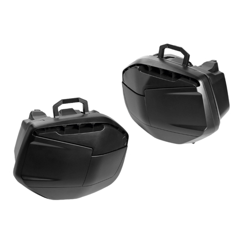
Kit valigie semirigide laterali / Semi-rigid side pannier kit - 96780011A
1 Telaietto supporto borse
2 Vite TBEI M8x45
3 Recuperatore di gioco
4Ghiera
5 Cablaggio posteriore sinistro
6 Cablaggio posteriore destro
7 Fanale posteriore
8 Indicatore posteriore destro
9 Indicatore posteriore sinistro
10 Dado autobloccante
11 Gommino
12 Rosetta
13 Distanziale
14 Vite TEF M5x22
15 Piastrino massa destro
16 Piastrino massa sinistro
17 Vite STEI M8x30
1 Pannier subframe
2 TBEI screw M8x45
3 Clearance adjuster
4Nut
5 LH rear wiring loom
6 RH rear wiring loom
7 Tail light
8 RH rear indicator
9 LH rear indicator
10 Self-locking nut
11 Rubber block
12 Washer
13 Spacer
14 TEF screw M5x22
15 RH ground plate
16 LH ground plate
17 STEI screw M8x30
16
9
2
5
8
12
17
3
17
10
11
13 15 7
13
11
10
12
14
342
4
1
614
Pag. - Page 2/17 Cod. ISTR - 508 ED./ED. 01
18 M8 hole plug
19 Outlet plug
20 Short pannier retainer
21 Rear sprocket fastener
22 Handle
23 Rear cat's eye
24 TCEIF screw M8x25
25 Flat washer
26 TSPEI screw M6x20
27 Socket cap screw M6x20
28 Long pannier retainer
29 RH side pannier
30 LH side pannier
31 Pannier heat shield
32 TBEIF screw M5x16 (q.ty 5)
33 Washer (q.ty 5)
34 Spacer (q.ty 5)
35 Waterproof cover (q.ty 2)
18
29
34
19
28
1
20
32
33
18
31
23
26
20
18
21
27 30
22
35
26
21 20
20
24
25
27
28
18 Tappo foro M8
19 Tappo per presa
20 Funghetto aggancio borse corto
21 Fissaggio a corona
22 Maniglia
23 Catadiottro posteriore
24 Vite TCEIF M8x25
25 Rosetta piana
26 Vite TSPEI M6x20
27 Vite TCEI M6x20
28 Funghetto aggancio borse lungo
29 Borsa destra
30 Borsa sinistra
31 Paracalore borsa
32 Vite TBEIF M5x16 (q.tà 5)
33 Rosetta (q.tà 5)
34 Distanziale (q.tà 5)
35 Sacca impermeabile (q.tà 2)
Pag. - Page 3/17Cod. ISTR - 508 ED./ED. 01
Note
Read the instructions on the first
page carefully before proceeding.
Warning
Have the kit installed by a trained
technician or at a DUCATI Authorized
Workshop.
Removing the original
components
Warning
Incorrect installation of this kit may
put the rider’s safety at risk.
Remove seat as specified in "Removing the
Seat".
Remove rear mudguard as specified in
"Removing rear mudguard".
Unscrew the six screws (B) and remove the
cover guard (A).
Loosen screw (E) and release keylock (F).
Unscrew the four screws (H) and remove
keylock unit (G) keeping washers (I).
Loosen screw (G1) and remove knob (G2),
spring (G3) and pin (G4) from keylock (G).
Fully remove rear grab handle (D) and lift to
free it from the retainer tooth (L1).
Disconnect connectors (P6) and (N6) from
rear tail lights (P) and (N).
Loosen screw (P4) with washer (P5) and
remove RH tail light (P) towards the back.
Remove spacers (P1), (P3) and rubber block
(P2) from glove compartment (L).
Loosen screw (N4) with washer (N5) and
remove LH tail light (N) towards the back.
Remove spacers (N1), (N3) and rubber block
(N2) from glove compartment (L).
Remove rubber blocks (M) from glove
compartment (L).
C
P
B
D
C
A
L
G
E
FH
G1
G2
G3
G4
I
G1
P1
P6
L
M
P2 P3 P5 N4 N5
N3
N2
N1
N
M
N6
Note
Prima di iniziare l’operazione, leggere
attentamente le avvertenze riportate nella
prima pagina.
Attenzione
Le operazioni di seguito riportate
devono essere eseguite da un tecnico
specializzato o da un’officina autorizzata
DUCATI.
Smontaggio componenti
originali
Attenzione
Le operazioni di seguito riportate se
non eseguite a regola d’arte possono
pregiudicare la sicurezza del pilota.
Rimuovere la sella seguendo quanto
riportato al capitolo “Smontaggio sella”.
Rimuovere il parafango posteriore
seguendo quanto riportato al capitolo
"Smontaggio parafango posteriore".
Svitare le sei viti (B) e rimuovere il coperchio
(A).
Svitare le viti (E) e sganciare il blocco chiave
(F).
Svitare le quattro viti (H) e rimuovere il
gruppo blocchetto (G) recuperando le
rondelle (I).
Svitare la vite (G1) e smontare il pomello
(G2), la molla (G3) e il piolo (G4) dal
blocchetto (G).
Sfilare il maniglione posteriore (D) fino a
battuta e sollevare per svincolarlo dal
dentino di fermo (L1).
Scollegare i connettori (P6) e (N6) dei fanali
posteriori (P) e (N).
Svitare la vite (P4) con rondella (P5) e sfilare
verso la parte posteriore il fanale destro (P).
Rimuovere i distanziali (P1), (P3) e il
gommino (P2) dalla vasca portaoggetti (L).
Svitare la vite (N4) con rondella (N5) e sfilare
verso la parte posteriore il fanale sinistro
(N).
Rimuovere i distanziali (N1), (N3) e il
gommino (N2) dalla vasca portaoggetti (L).
Rimuovere i gommini (M) dalla vasca
portaoggetti (L).
Pag. - Page 4/17 Cod. ISTR - 508 ED./ED. 01
Kit installation
Caution
Check that all components are clean
and in perfect condition before installation.
Take adequate measures to avoid damaging
the internal components of the engine.
Pre-assembly of pannier subframe
Insert LH rear indicator (9) retaining nut (10)
in the seat on the LH side of pannier
subframe (1).
Insert LH rear indicator wiring (9A) in hole
(1A) going through the inner part of nut (10)
and bring turn indicator fully home on the
subframe.
Start nut (10) on turn indicator thread and
tighten it to a torque of 5±10% Nm.
Insert LH rear turn indicator wiring (9A)
through hole (1B).
Repeat the same procedure to assemble
RH rear turn indicator (8).
Remove protective film on rear side of LH
ground plate (16) and apply it on LH rear tail
light (7).
Remove protective film on rear side of RH
ground plate (15) and apply it on RH rear tail
light (7).
Fit grommets (11) in relative holes on
pannier subframe (1) and introduce spacers
(13) in grommets (11).
Insert wiring (7A) through hole (1B) on LH
pannier subframe (1) and bring tail light fully
home (7) with buffers (15) and (16) on
subframe.
Start screws (14) with washers (12) on
pannier subframe inner part securing tail
light (7).
Tighten screws (14) to a torque of 5±10%
Nm.
Grease clearance adjusters threads (3) and
nuts (4) using GADIUS S2 V220 AD2
grease, making sure not to apply grease on
the clearance adjusters surface (3A).
Screw clearance adjusters (3) to their
washers (4), until the sides with the flats are
at the same level, as shown in the figure (X).
Screw clearance adjusters (3) with washers
(4) up to the edge of frame bushes internal
surface, as shown in the figure (Y).
1
15
4
4
3
9
14
12
16
10
1A
1B
9A
8A
8
13
11 13
7
7A
1B
12
14
43
3
1
3A
Montaggio componenti kit
Importante
Verificare, prima del montaggio, che
tutti i componenti risultino puliti e in
perfetto stato.
Adottare tutte le precauzioni necessarie per
evitare di danneggiare qualsiasi parte nella
quale ci si trova ad operare.
Premontaggio telaietto supporto borse
Inserire il dado (10) di fissaggio indicatore
posteriore sinistro (9) nella sede ricavata sul
lato sinistro del telaietto supporto borse (1).
Inserire il cablaggio (9A) dell'indicatore
posteriore sinistro nel foro (1A) facendolo
passare all'interno del dado (10) e portare a
battuta l'indicatore di direzione sul telaietto.
Avvitare il dado (10) sul filetto dell'indicatore
di direzione e serrarlo alla coppia di
serraggio 5±10% Nm.
Inserire il cablaggio (9A) dell'indicatore
posteriore sinistro attraverso il foro (1B).
Ripetere la stessa operazione per il
montaggio dell'indicatore posteriore destro
(8).
Rimuovere la pellicola protettiva presente
sul lato posteriore del piastrino massa
sinistro (16) e applicarlo sul lato posteriore
sinistro del fanale posteriore (7).
Rimuovere la pellicola protettiva presente
sul lato posteriore del piastrino massa
destro (15) e applicarlo sul lato posteriore
destro del fanale posteriore (7).
Montare i gommini (11) nei relativi fori
ricavati sul telaietto supporto borse (1)e
inserire i distanziali (13) nei gommini (11).
Inserire il cablaggio (7A) attraverso il foro
(1B) ricavato sul lato sinistro del telaietto
supporto borse (1) e portare a battuta il
fanale posteriore (7) con tamponi (15) e (16)
sul telaietto.
Impuntare le viti (14) con rondelle (12) sulla
parte interna del telaietto supporto borse
fissando il fanale posteriore (7).
Serrare le viti (14) alla coppia di serraggio
5±10% Nm.
Ingrassare i filetti dei recuperatori di gioco
(3) e ghiere (4) con grasso GADIUS S2 V220
AD2, facendo attenzione che il grasso non
vada sul piano (3A)dei recuperatori di gioco.
Avvitare i recuperatori di gioco (3) nelle
relative ghiere (4), fino a portare i lati con le
prese di chiave, sullo stesso piano, come
mostrato in figura (X).
Avvitare i recuperatori di gioco (3) con
ghiere (4) fino a portarli a filo col piano
interno delle boccole telaio, come mostrato
in figura (Y).
Pag. - Page 5/17Cod. ISTR - 508 ED./ED. 01
Remove protective film from cat's eyes (23)
rear side.
Fit cat's eye (23) to pannier subframe (1),
exerting an even pressure on the whole
cat's eye surface (23).
Note
The cat's eye (23) must be placed as
shown in the figure, in the pannier
subframe area (1).
Connect RH rear wiring (6) to RH rear turn
indicator wiring (8A).
Lay down complete wiring between cable
ring pins (1C), (1D) and fit rear sprockets
(21) on pins locking wiring to frame.
Connect LH rear wiring (5), pairing:
connector (5A) to rear tail light wiring (7A);
connector (5B) to LH rear turn indicator
wiring (9A).
Lay down complete wiring between cable
ring pins (1E), (1F) and (1G).
Place rear sprockets (21) on the pins shown
in figure (Z) locking wiring to frame.
Take exceeding cable and fix it to wiring
using 2 ties (Q), as shown in the figure (Z).
6
23
21
5B
1E
1C 1
21
8A
1D
5A
5
7A
18A
9A
18B
1F
Q
1G
Rimuovere la pellicola protettiva presente
sul lato posteriore del catadiottro (23).
Applicare il catadiottro (23) sul telaietto
supporto borse (1), premendo
uniformemente su tutta la superficie del
catadiottro (23) stesso.
Note
Il catadiottro (23) deve essere
posizionato, orientandolo come mostrato in
figura, in corrispondenza dell'area del
telaietto supporto borse (1).
Collegare il cablaggio posteriore destro (6) al
cablaggio indicatore di direzione posteriore
destro (8A).
Disporre il cablaggio completo tra i pioli
passacavo (1C), (1D) e montare le corone
(21) sui pioli bloccando il cablaggio al telaio.
Collegare il cablaggio posteriore sinistro (5),
accoppiando:
il connettore (5A) al cablaggio fanale
posteriore (7A);
il connettore (5B) al cablaggio indicatore di
direzione posteriore sinistro (9A).
Disporre il cablaggio completo tra i pioli
passacavo (1E), (1F) e (1G).
Posizionare le corone (21) sui pioli indicati in
figura (Z) bloccando il cablaggio al telaio.
Raccogliere le eccedenze di cavo e fissarle
al cablaggio con 2 fascette (Q), come
indicato in figura (Z).

Other Ducati Motorcycle Accessories manuals

Ducati 97380141A User manual

Ducati

Ducati 97380141A User manual

Ducati 96780561B User manual

Ducati

Ducati 96780561B User manual

Ducati PERFORMANCE 979000152 User manual

Ducati

Ducati PERFORMANCE 979000152 User manual

Ducati Performance 97380261A User manual

Ducati

Ducati Performance 97380261A User manual

Ducati 96780311A User manual

Ducati

Ducati 96780311A User manual

Ducati 96980731A User manual

Ducati

Ducati 96980731A User manual

Ducati 96981071A User manual

Ducati

Ducati 96981071A User manual

Ducati 96480931A User manual

Ducati

Ducati 96480931A User manual

Ducati 96780571A User manual

Ducati

Ducati 96780571A User manual

Ducati 96981061A User manual

Ducati

Ducati 96981061A User manual

Ducati 97180531A User manual

Ducati

Ducati 97180531A User manual

Ducati 96989981A User manual

Ducati

Ducati 96989981A User manual

Ducati Multistrada 1200 User manual

Ducati

Ducati Multistrada 1200 User manual

Ducati KIT Top Case 1106 User manual

Ducati

Ducati KIT Top Case 1106 User manual

Ducati 97380331A User manual

Ducati

Ducati 97380331A User manual

Ducati ISTR - 788 / 00 User manual

Ducati

Ducati ISTR - 788 / 00 User manual

Ducati 96680441A User manual

Ducati

Ducati 96680441A User manual

Ducati 96780511A User manual

Ducati

Ducati 96780511A User manual

Ducati Performance 97380071A User manual

Ducati

Ducati Performance 97380071A User manual

Ducati 97180741A User manual

Ducati

Ducati 97180741A User manual

Ducati 96380031A User manual

Ducati

Ducati 96380031A User manual

Ducati Performance 96780881A User manual

Ducati

Ducati Performance 96780881A User manual

Ducati 96680691A User manual

Ducati

Ducati 96680691A User manual

Ducati SBK 1199 User manual

Ducati

Ducati SBK 1199 User manual

Popular Motorcycle Accessories manuals by other brands

SRC H-ADV150-04-01AL quick start guide

SRC

SRC H-ADV150-04-01AL quick start guide

DMD P1 owner's manual

DMD

DMD P1 owner's manual

GIVI Airflow AF1110 manual

GIVI

GIVI Airflow AF1110 manual

Suzuki 99143-00A1 000 Series installation instructions

Suzuki

Suzuki 99143-00A1 000 Series installation instructions

Cardo Systems FREECOM 4+ Pocket guide

Cardo Systems

Cardo Systems FREECOM 4+ Pocket guide

Shark S 700 user manual

Shark

Shark S 700 user manual

R&G CR0081 Fitting instructions

R&G

R&G CR0081 Fitting instructions

SRC B-TRK502-01-01-SL quick start guide

SRC

SRC B-TRK502-01-01-SL quick start guide

hepco & becker 6307520 00 01 manual

hepco & becker

hepco & becker 6307520 00 01 manual

HOMCOM AA0-077 user manual

HOMCOM

HOMCOM AA0-077 user manual

hepco & becker 6307558 00 01 manual

hepco & becker

hepco & becker 6307558 00 01 manual

SHOEI JO Instructions for use

SHOEI

SHOEI JO Instructions for use

Wunderkind Custom 106503-F15 Installation and safety

Wunderkind Custom

Wunderkind Custom 106503-F15 Installation and safety

Suzuki 57100-05881 installation instructions

Suzuki

Suzuki 57100-05881 installation instructions

SIKH HELMETS Y-61 quick start guide

SIKH HELMETS

SIKH HELMETS Y-61 quick start guide

Dräger HPS 3500 Instructions for use

Dräger

Dräger HPS 3500 Instructions for use

M-WAVE SKI manual

M-WAVE

M-WAVE SKI manual

Kuryakyn 6212 installation instructions

Kuryakyn

Kuryakyn 6212 installation instructions

manuals.online logo
manuals.online logoBrands
  • About & Mission
  • Contact us
  • Privacy Policy
  • Terms and Conditions

Copyright 2025 Manuals.Online. All Rights Reserved.