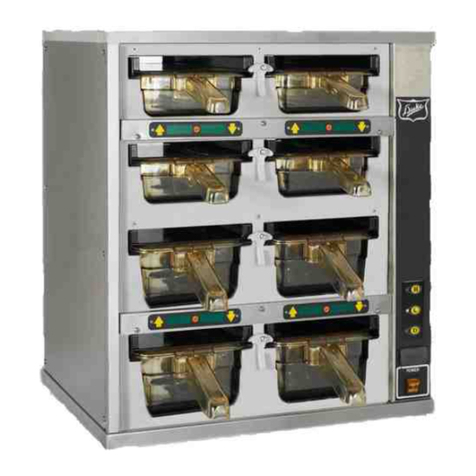
Duke HDC3 User manual

Service Manual
DRY CHANNEL
MODELS
HDC3/HDC6
Please read this manual completely before attempting
to install, operate or service this equipment
This document is prepared for trained Duke service technicians. It is not to be used by anyone not
properly qualied to perform these procedures.
This Service Manual is not all encompassing. If you have not been trained on servicing this product,
be sure to read the manual completely before attempting servicing. Be sure all necessary tools, test
equipment, and skills are available. Those procedures for which you do not have the proper skills
and test equipment must be performed only by a qualied Duke trained service technician.
This manual is Copyright © 2013 Duke Manufacturing Company. All rights reserved.
Reproduction without written permission is prohibited. Duke is a registered
trademark of the Duke Manufacturing Company.
Duke Manufacturing Company
2305 N. Broadway
St. Louis, MO 63102
Phone: 314-231-1130
Toll Free: 1-800-735-3853
Fax: 314-231-5074
www.dukemfg.com
P/N 219217C

Service Manual for Dry Channel HDC3/HDC6 Units
2
IMPORTANT WARNING AND SAFETY INFORMATION
WARNING
READ THIS MANUAL THOROUGHLY BEFORE OPERATING, INSTALLING, OR
PERFORMING MAINTENANCE ON THE EQUIPMENT.
WARNING
FAILURE TO FOLLOW INSTRUCTIONS IN THIS MANUAL CAN CAUSE PROPERTY
DAMAGE, INJURY OR DEATH.
WARNING
DO NOT STORE OR USE GASOLINE OR OTHER FLAMMABLE VAPORS OR
LIQUIDS IN THE VICINITY OF THIS OR ANY OTHER APPLIANCE.
WARNING
DO NOT OPERATE THIS EQUIPMENT WITHOUT PROPERLY PLACING AND
SECURING ALL COVER AND ACCESS PANELS.
CAUTION
Observe the following:
•Provide and maintain adequate minimum clearances from all walls and combustible materials.
•Provide and maintain adequate clearance for air openings.
•Keep the equipment area free and clear of combustible material.
• Operateequipmentonlyonthetypeofelectricityindicatedonthespecicationplate.
•Retain this manual for future reference.

3
Service Manual for Dry Channel HDC3/HDC6 Units
TABLE OF CONTENTS
IMPORTANT SAFETY INSTRUCTIONS...........................................................................2
INTRODUCTION...............................................................................................................4
GENERAL....................................................................................................................4
MODEL DESIGNATIONS ............................................................................................5
MAIN FEATURES..............................................................................................................6
RELAY BOX.................................................................................................................6
CONTROL DISPLAY ...................................................................................................6
COMPONENT REPLACEMENT .......................................................................................7
TOOLS REQUIRED.....................................................................................................7
CONTROL DISPLAY ...................................................................................................7
CONTROL BOARD OR MYLAR COVER....................................................................7
RELAY BOX.................................................................................................................8
Main Power On/Off Switch ....................................................................................8
Solid State Relays .................................................................................................9
24 Volt Step-Down Transformer ........................................................................... 9
CHANNEL ASSEMBLY..............................................................................................10
TESTING AND TROUBLESHOOTING ........................................................................... 11
COMPONENT TESTING........................................................................................... 11
Primary Power Check.......................................................................................... 11
Fault Conditions................................................................................................... 11
24 Volt Step-Down Transformer ..........................................................................12
Heater Element and Hi-Limit Thermostat ............................................................12
RTD ...........................................................................................................................13
SEQUENCE OF OPERATION ........................................................................................14
TROUBLESHOOTING CHART .......................................................................................15
WIRING DIAGRAM .........................................................................................................16

Service Manual for Dry Channel HDC3/HDC6 Units
4
On/O
Function Control
Button
Select
Buttons
DISPLAYDISPLAY
HEAT ON
READY
GENERAL
The Duke HDC3 Dry Channel unit maintains the
factory set point temperature on 3 channels (front,
back, and center). The Duke HDC6 Dry Channel
unit maintains the factory set point temperature
on 6 channels. Each channel has an A and B
zone. The Main Power On/Off Switch is located
on the Relay/Control Box (herein after referred to
as Relay Box). A display panel will cycle through
the temperature of each channel followed by fault
messages if a fault is detected.
The display temperature will be the average of
the two zones.
INTRODUCTION
Relay
Box
Display
Box
I
DRY CHANNEL TEMPERATURE
PROG
Tub
Main Power
ON/OFF Switch
Channel 3
Zones 3A & 3B
Channel 1
Zones 1A & 1B
Channel 2
Zones 2A & 2B
Figure 1. Dry Channel Major Components
Figure 2. Channels and Zones
Pressing the ON button on the Control Display
activates the display. Pressing the up arrow
will cycle through the six temperature zones,
displaying the actual temperatures. Pressing
the down arrow will cycle through the set point
temperature for each channel. The factory set
point temperature is 275°F. The HEAT ON LED
will indicate an activated relay in any zone. The
READY LED is activated when all zones reach
the set point temperature. A fault message will
be displayed to indicate any zone that does
not reach the set point temperature within 45
minutes of power up.
Figure 3. Control Display

5
Service Manual for Dry Channel HDC3/HDC6 Units
MODEL DESIGNATIONS
The following chart lists the different model designations and provides information on the weight and
electrical requirements.
TABLE 1. MODEL SPECIFICATIONS
MODEL NO. SHIPPING WT. ELECTRICAL SPECIFICATIONS
HDC3-37.5-208 160 lbs (59.7 kg) 208VAC, 10.1A, 2100W, 50/60Hz
HDC-37.5-240 160 lbs (59.7 kg) 240VAC 8.8A, 2100W, 50/60Hz
HDC6-37.5-208 315 lbs (117.6 kg) 208VAC, 20.1A, 4200W, 50/60Hz
HDC6-37.5-240 315 lbs (117.6 kg) 240VAC, 17.5A, 4200W, 50/60Hz

Service Manual for Dry Channel HDC3/HDC6 Units
6
RELAY BOX
Figure 4. Relay Box
The Main Power On/Off Switch is located on
the lower right side of the Relay Box. This is a
lighted double pull single throw (DPST) switch
rated at 20 Amperes. The Relay Box houses a 24
Volt Step-Down Transformer and six Solid State
Relays (SSR).
CONTROL DISPLAY
Figure 5. Control Display
The display provides a readout of actual
temperature, set point temperature and fault
conditions.
The control board inside the Control Display
maintains the temperature of all three channels.
Each channel has anA& B zone. The control board
monitors each zone’s temperature and activates a
relay to supply power to the heater for that zone.
When the ON/OFF button is pressed, the display
cycles through the temperature of each channel.
If a fault is detected, the fault code is displayed.
The displayed temperature will be the average of
the two zones associated with that channel.
MAIN FEATURES
Main Power
On/Off Switch
I
On/O
Function Control
Button
Select
Buttons
DISPLAYDISPLAY
HEAT ON
READY

7
Service Manual for Dry Channel HDC3/HDC6 Units
DRY CHANNEL TEMPERATURE
On/O
Function Control
Button
Select
Buttons
DISPLAYDISPLAY
HEAT ON
READY
WARNING:
BEFORE ANY REPLACEMENT
PROCEDURE BEGINS, THE HDC3/
HDC6 MUST BE ISOLATED FROM
THE POWER SOURCE TO PREVENT
POSSIBLE ELECTRICAL SHOCK.
TOOLS REQUIRED
The only tools required are normal hand-tools.
CONTROL DISPLAY
Figure 6. Control Display
The location of the Control Display will vary by
application and cabinet choice. It is mounted from
the front and is held in place by four screws.
1. Place the Main Power On/Off Switch in the off
position.
2. Disconnect the Dry Channel unit from its
power source. Use proper Lockout/Tagout
procedures.
3. Remove the four screws securing the Control
Display and move it away from mounting
surface.
4. If the Control Display is to be completely
removed, tag and disconnect the wires.
5. Remove Control Display.
6. Reverse the procedure to install Control
Display.
NOTE: The following Control Display component
removal is based on the Control Display having
already been removed from its mounting
surface.
WARNING:
BEFORE ANY REPLACEMENT
PROCEDURE BEGINS, THE HDC3/
HDC6 MUST BE ISOLATED FROM
THE POWER SOURCE TO PREVENT
POSSIBLE ELECTRICAL SHOCK.
CONTROL BOARD OR MYLAR COVER
Figure 7. Exploded View of Control Display
1. With the Control Display removed from its
mounting surface, tag and disconnect wires.
2. Remove the four cover retaining nuts.
COMPONENT REPLACEMENT

Service Manual for Dry Channel HDC3/HDC6 Units
8
POWER
O
ON
OFF
DANGER
3. Remove the Control Board nuts from the four
studs.
4. Reverse the procedure to install a new Control
Board or Mylar Cover.
WARNING
BEFORE ANY REPLACEMENT
PROCEDURE BEGINS, THE HDC3/
HDC6 MUST BE ISOLATED FROM
THE POWER SOURCE TO PREVENT
POSSIBLE ELECTRICAL SHOCK.
RELAY BOX
Figure 8. Relay Box
Typically the Relay Box is mounted on the bottom
of the Dry Channel Tub on the right side. The actual
location may vary based on installation application
orcabinetcongurationused.
1. Place the Main Power On/Off Switch in the off
position.
2. Remove the Dry Channel unit from its
power source. Use proper Lockout/Tagout
procedures.
3. Remove the four screws securing the Relay
Box to its mounting surface.
4. If complete Relay Box is to be replaced, tag
and disconnect wires.
5. Remove Relay Box.
6. Reverse procedure to assemble and install
Relay Box.
WARNING
BEFORE ANY REPLACEMENT
PROCEDURE BEGINS, THE HDC3/
HDC6 MUST BE ISOLATED FROM
THE POWER SOURCE TO PREVENT
POSSIBLE ELECTRICAL SHOCK.
NOTE: The following Relay Box component
removal and replacement assumes the Relay Box
has already been removed from the Dry Channel
unit.
Figure 9. Exploded View of Relay Box

9
Service Manual for Dry Channel HDC3/HDC6 Units
Transformer
Solid State Relay
(SSR)
Main Power On/Off Switch
1. Remove the four screws securing the Relay
Box cover. Set the cover aside for reuse.
2. Tag and disconnect the Main Power On/Off
Switch wires.
3. Squeeze the Main Power On/Off Switch
retaining springs and push the switch out
through the front of the box.
4. Reverse this procedure to install a new Main
Power On/Off Switch.
WARNING
BEFORE ANY REPLACEMENT
PROCEDURE BEGINS, THE HDC3/
HDC6 MUST BE ISOLATED FROM
THE POWER SOURCE TO PREVENT
POSSIBLE ELECTRICAL SHOCK.
Solid State Relays (SSR)
Figure 10. View of SSR
1. Using a Multimeter, determine which SSR has
failed.
2. Tag and disconnect the wires from the faulty
SSR.
3. Remove the two screws that attach the SSR
to the board and remove the faulty SSR.
4. Reverse procedure to install a new SSR.
24 Volt Step-Down Transformer
Figure 11. Step-Down Transformer 208/240V
Primary, 24V Secondary
WARNING
BEFORE ANY REPLACEMENT
PROCEDURE BEGINS, THE HDC3/
HDC6 MUST BE ISOLATED FROM
THE POWER SOURCE TO PREVENT
POSSIBLE ELECTRICAL SHOCK.
1. Using a multimeter test the 24 Volt Step-Down
Transformer to determine whether or not it is
the reason for the failure.
2. Tag and disconnect wires from Transformer.
3. Remove four nuts attaching Transformer
to studs on the relay box body and remove
Transformer.
4. Reverse this procedure to install a new
24 Volt Step-Down Transformer.

Service Manual for Dry Channel HDC3/HDC6 Units
10
Center Channel
Screws
End Channels
Center
Channels
Screw
End Channels
CHANNEL ASSEMBLY
A heating zone consists of a Heater Element,
Hi-Limit Thermostat and an RTD. These
components are embedded in a foil wrap that is
attached to the bottom of each ChannelAssembly.
Thefoilwrapisnotserviceableintheeld.The
entire Channel Assembly must be replaced in the
event of a failure.
1. Set the Main Power On/Off Switch to the Off
position.
2. Disconnect the Dry Channel unit from its
power source. Use proper Lockout/Tagout
procedures.
3. Remove six screws (three on each side)
attaching the channel top frame to the tub.
Figure 12. HDC6 Channel Conguration
Figure 13. HDC3 Channel Conguration
4. Carefully lift the ChannelAssembly out, taking
care not to damage wire connections.
5. Tag and disconnect the wires from the foil
wrap on the Channel Assembly to the Control
Board.
6. Reverse this procedure to install a new Dry
Channel Assembly.
NOTE: The End Channels are a different assembly
from the Center Channels. Install the appropriate
channel assembly in its position in the tub.
7. Return the Dry Channel unit to service and
check for proper operation.

11
Service Manual for Dry Channel HDC3/HDC6 Units
COMPONENT TESTING
Most component testing can be performed using
a Digital Multimeter.
NOTE: When a continuity test is being performed,
the HDC3/HDC6 must be isolated from the
power source to prevent damage to the test
equipment.
Primary Power Check
CAUTION: Input voltage source must
match voltage indicated on
dataplate. Voltage should be 208
or 240 VAC depending upon the
application.
1. Check the input voltage source for correct
measurement of 208 or 240 VAC. If input
voltage is not present, check for open circuit
breakers or fuses supplying the input power.
2. Measure the voltage across the input terminals
on the Main Power On/Off Switch. Voltage
should be the same as input voltage source.
If voltage is not present, check power source
and power cord.
3. Set the Main Power On/Off Switch to on and
check for source voltage across the switch
output terminals. If voltage is not present
replace switch.
4. Measure voltage across primaryof24 Volt Step-
Down Transformer. If voltage is not present,
check wiring. If input voltage is present, the
primary power check is complete.
TESTING AND TROUBLESHOOTING
Fault Conditions
Fault conditions are indicated on the Control
Display.
1. High Temperature Fault – For a High
Temperature Fault the display will show “HIX”,
where X indicates the channel (“F” for front,
“C” for center, and “b” for back). A buzzer will
sound for one second every 30 seconds. The
operator can cancel this alarm by pressing any
button on the Control Panel. The alarm will
reactivate after 20 minutes if the problem has
notbeenrectied.Bothrelaysforthechannel
will be turned off while the fault exists.
2. Low Temperature Fault – For a Low
Temperature Fault the display will show
“LOX”, where X indicates the channel
(“F” for front, “C” for center, and “B” for back).
A buzzer will sound for one second every 30
seconds. The operator can cancel this alarm
by pressing any button on the Control Panel.
The alarm will reactivate after 20 minutes if
theproblemhasnotbeenrectied.
3. Probe Open/Short – For a Probe Open/ Short
Fault the display will show “PRX”, where X
indicates the channel (“F” for front, “C” for
center and “B” for back). The operator can
cancel this alarm by pressing any button on
the Control Panel. The alarm will reactivate
after 20 minutes if the problem has not been
rectied. The relays for both zones of the
channel with a probe fault will be turned off
while the fault exists. The control will display
000°F for the temperature of the channel with
the fault condition.

Service Manual for Dry Channel HDC3/HDC6 Units
12
124 Ohms 124 Ohms
248 Ohms
24 Volt Step-Down Transformer
The 24 Volt Step-Down Transformer (Transformer)
is located in the Relay Box.
WARNING
USE EXTREME CARE WHEN
PERFORMING THIS TEST.
MEASUREMENTS ARE PERFORMED
ON CIRCUITS WITH VOLTAGE
APPLIED.
1. Set the Main Power On/Off Switch to the off
position.
2. Remove Relay Box cover.
CAUTION: Ensure that primary of
Transformer is correctly
connected for input voltage
source.
3. Set voltmeter to AC and select a range to
measure the 208/240 VAC input voltage
level.
4. Attach voltmeter across Transformer primary
terminals.
5. Set the Main Power On/Off Switch to on.
Measure voltage across the Transformer
primary. Voltage should be the same as the
input voltage source. If no voltage is present,
check wiring to Transformer.
6. If correct voltage is present at primary, measure
the secondary voltage.
7. If the secondary voltage is near 24 VAC,
Transformer is operating properly. If voltage is
low or 0 VAC, disconnect wire from Transformer
secondary and recheck secondary voltage.
If voltage is still near 0 VAC, replace
Transformer.
8. If voltage is now near 24 VAC, a short exists
somewhere else in the circuit. Further trouble
isolation testing is required.
Heater Element and Hi-Limit Thermostat
Check the Heater Element and Hi-Limit Thermostat
by measuring the resistance of the Heater Element.
To access the Heater Element, follow the procedure
described in the CHANNELASSEMBLY paragraph
in the COMPONENT REPLACEMENT section.
1. Remove the suspect Channel Assembly from
the Dry Channel Tub.
2. Disconnect the wires to the ChannelAssembly
to be tested.
3. Connect an ohmmeter across the heater leads
and verify that the resistance is approximately
124Ωbetween one end of the Heater Element
and the Hi-Limit Thermostat. The resistance
across both heat elements should be
approximately 248Ω
4. Replace Dry Channel Assembly if the Foil
Wraps tests open.
Figure 14. Foil Wrap Heater Conguration

13
Service Manual for Dry Channel HDC3/HDC6 Units
1000 Ohms 1000 Ohms
RTD
Check the RTD Thermocouple by measuring
the resistance between the two lead wires.
There are two RTD probes in each Foil Wrap. To
access the RTD, follow the procedure described
in the CHANNEL ASSEMBLY paragraph in
COMPONENT REPLACEMENT section.
1. Disconnect the RTD wires.
2. Connect an ohmmeter across the RTD leads
and verify that the resistance is approximately
1000Ωat ambient room temperature.
3. Check both RTDs in the Channel Assembly.
4. Replace the Dry Channel Assembly if an RTD
is defective.
Refer to the Wiring Diagram.
Figure 15. Foil Wrap with RTD Connectors

Service Manual for Dry Channel HDC3/HDC6 Units
14
1. Plug HDC3/HDC6 unit into the proper line
source per the dataplate on the unit.
2. Set the Main Power On/Off Switch to on.
3. Line voltage is applied through the Main Power
On/Off Switch to the following:
a. To the primary of the 24 Volt Step-Down
Transformer.
b. Through a junction box to one side of
each of the six Hi-Limit Thermostats.
c. Through each element and to one side
of each respective SSR.
4. The secondary of the Transformer provides
24 VAC to the Control Display, allowing the
Control Board to power on.
5. The Control Board provides a reference set
point temperature and monitors the channel
heat level through the RTD’s. If the channel
temperature is less than the set point
temperature for a given channel, the SSR for
that channel is activated.
6. Voltage is routed through the SSR to the
other side of each Heater Element causing
the Heater Element to operate through the
normally closed Hi-Limit Thermostat and begin
raising the temperature of the channel.
7. When the heat reaches the set point
temperature (normally set at 275°F), the SSR
for that channel is turned off disconnecting the
Heater Element.
8. If the SSR does not shut off and the
temperature continues to rise, the Hi-Limit
Thermostat opens at 375°F cutting off power
to the Heater Element. At the same time
the Control Board provides a “High Temp
Fault” indication to the display and turns off
both SSRs to the faulty channel. An alarm
is sounded every 30 seconds. The operator
can cancel this alarm by pressing any
button on the Control Panel. If the fault has
not been corrected, the alarm will reactivate
in 20 minutes.
9. The temperatures measured by the RTD’s,
are routed to the Control Display. Each
zone’s temperature within the channel will be
displayed when the up button is pressed.
10. The set point temperature for each channel can
be displayed by pressing the down button.
SEQUENCE OF OPERATION

15
Service Manual for Dry Channel HDC3/HDC6 Units
REMEDY
TROUBLESHOOTING
SYMPTOM
Heating Elements do not
heat.
One Heating Element does
not heat.
Heating Elements
operating but no indication
on the Display Box.
CAUSE
Unit not plugged in
Main Power On/Off Switch not in on position
Faulty Control Board
Defective Heating Element or Hi-Limit Thermostat
Defective RTD
Defective SSR
Defective Control Board
Defective Display Board
Plug unit in to proper power outlet.
Move the Main Power On/Off Switch to on position.
Replace Control Board.
Check resistance across Heating Element and
Hi-Limit Thermostat. It should be around 124Ω.
Replace Channel Assembly if test fails.
Check resistance across RTD at ambient room
temperature. Resistance should be approximately
1000Ω. Replace Channel Assembly if test fails.
Replace SSR.
Replace Control Board.
Replace the Display Board.

Service Manual for Dry Channel HDC3/HDC6 Units
16
WIRING DIAGRAM
SSR-3B SSR-3A SSR-2B SSR-2A SSR-1B SSR-1A
L2
L1
G
D
R
Y
W
E
L
L
R
T
D
s
PROBE 3A
PROBE 2A
PROBE 1A
PROBE 3B
PROBE 2B
PROBE 1B
To connectorTo connector
High Limit
High Limit
High Limit
Heating Element 3A
(Back Left)
Heating Element 2A
(Center Left)
Connector
RTD Cable
Electric Control Board
PRB-1A
PRB-2A
PRB-3A
PRB-1B
PRB-2B
PRB-3B
C3BC2B C1B
C3A C2A C1A
24VAC

17
Service Manual for Dry Channel HDC3/HDC6 Units
SINGLE ZONE WIRING DIAGRAM

Service Manual for Dry Channel HDC3/HDC6 Units
18
NOTES:

19
Service Manual for Dry Channel HDC3/HDC6 Units
NOTES:

Service Manual for Dry Channel HDC3/HDC6 Units
20
Duke Manufacturing Company
2305 N. Broadway
St. Louis, MO 63102
Phone: 314-231-1130
Toll Free: 1-800-735-3853
Fax: 314-231-5074
www.dukemfg.com
P/N 219217C
This manual suits for next models
5
Table of contents
Other Duke Kitchen Appliance manuals