Duke X-STREAM WASH User manual

Installation and
Operation Manual
Please read this manual completely before attempting
to install, operate or service this equipment
This manual is Copyright © 2017 Duke Manufacturing Co. All rights reserved.
Reproduction without written permission is prohibited. Duke is a registered
trademark of the Duke Manufacturing Co.
Duke Manufacturing Co.
2305 N. Broadway
St. Louis, MO 63102
Phone: 314-231-1130
Toll Free: 1-800-735-3853
Fax: 314-231-5074
www.dukemfg.com
P/N 115152G
05/18/2017
X-STREAM WASH

Installation and Operation of X-STREAM WASH
2
TABLE OF CONTENTS
I. SAFETY AND ELECTRICAL WARNINGS .....................................................................3
II. GENERAL INFORMATION............................................................................................5
A. X-STREAM WASH SPECIFICATION ....................................................................5
III. INSTALLATION INSTRUCTIONS ................................................................................6
A. QUALIFIED PERSONNEL.....................................................................................6
B. DELIVERY AND INSPECTION ..............................................................................6
C. PLACEMENT.........................................................................................................6
D. PLUMBING REQUIREMENTS ..............................................................................6
E. ELECTRICAL CONNECTIONS .............................................................................7
F. XSTREAM WASH OPTIONS .................................................................................7
VI. OPERATION INSTRUCTIONS ....................................................................................8
A. INITIAL STARTUP..................................................................................................8
A-10 Fill Tanks with Water ..................................................................................8
A-20 Add Soap / Chemicals ...............................................................................8
A-30 Approved Chemicals..................................................................................8
B. PRE-SCRAPPING .................................................................................................9
C. LOADING WASH TANK.........................................................................................9
D. START THE WASH CYCLE.................................................................................10
E. CONTROL PANELS.............................................................................................10
E-10 Identifying Your Control Panel ..................................................................10
E-20 K1000 Control Panel................................................................................. 11
E-30 K5000 Control Panel.................................................................................17
V. SERVICE AND REPAIR ..............................................................................................25
VI. ELECTRICAL SCHEMATICS.....................................................................................26

3
Installation and Operation of X-STREAM WASH
I. SAFETY AND ELECTRICAL WARNINGS
THIS MANUAL HAS BEEN PREPARED FOR PERSONNEL QUALIFIED TO INSTALL
ELECTRICAL EQUIPMENT, WHO SHOULD PERFORM THE INITIAL FIELD STARTUP
AND ADJUSTMENTS OF THE EQUIPMENT COVERED BY THIS MANUAL.
READ THIS MANUAL THOROUGHLY BEFORE OPERATING, INSTALLING OR PERFORMING
MAINTENANCE ON THE EQUIPMENT.
: Failure to follow all the instructions in this manual can cause
property damage, injury or death.
: Improper installation, adjustment, alteration, service or maintenance
can cause property damage, injury or death.
: Electrical connections should be performed only by a certied
professional.
: Electrical and grounding connections must comply with the applicable
portions of the National Electrical Code and/or all local electric codes. Failure to
comply with this procedure can cause property damage, injury or death.
: Plumbing connections must comply with applicable sanitary, safety
and plumbing codes.
: Before connecting the unit to the electrical supply, verify that the
electrical and grounding connections comply with the applicable portions of the
National Electrical Code and/or other local electrical codes. Failure to comply with
this procedure can cause property damage, injury or death.
: Before connecting the unit to the electrical supply, verify that the
electrical connection agrees with the specications on the data plate. Failure to
comply with this procedure can cause property damage, injury or death.
: UL73 grounding instructions: This appliance must be connected to
a grounded, metal, permanent wiring system or an equipment-grounding conductor
must be run with the circuit conductors and connected to the equipment-grounding
terminal or lead on the appliance. Failure to comply with this procedure can cause
property damage, injury or death.
: Before performing any service that involves electrical connection
or disconnection and/or exposure to electrical components, always perform the
Electrical LOCKOUT/TAGOUT Procedure. Disconnect all circuits. Failure to comply
with this procedure can cause property damage, injury or death.

Installation and Operation of X-STREAM WASH
4
: Before removing any sheet metal panels or servicing this equipment,
always perform the Electrical LOCKOUT/TAGOUT Procedure. Be sure all circuits are
disconnected. Failure to comply with this procedure can cause property damage,
injury or death.
: Do not operate this equipment without properly placing and securing
all covers and access panels. Failure to comply with this procedure can cause
property damage, injury or death.
: Do not use or store gasoline or other ammable vapors or liquids
in the vicinity of this or any other appliance. Failure to comply can cause property
damage, injury or death.
: In the event of a power failure, do not attempt to operate this
appliance. Failure to comply can cause property damage, injury or death.

5
Installation and Operation of X-STREAM WASH
II. GENERAL INFORMATION
A. X-STREAM WASH SPECIFICATION
DIMENSIONS:
37"
28-7/8"
DRAIN
12"
DRAIN
18"
BOWL
DEPTH
12"
3"
6"
MODEL NUMBER KEY:
SSSTUVW-XXYY with sufxes. Where:
SSS Indicates the type of unit
XSW – Denotes an X-Stream wash unit
TIndicates the options
– – Denotes no options
H – Denotes the heated sanitizer sink option
C – Denotes that chemical injection sanitizer sink option
UIndicates the controller model number
1 – K1000 Control (Not available on units with a heated sanitizer sink)
5 – K5000 Control
VIndicates the heating element wattage used in the powered wash sink
2 – 2500 watt
5 – 5000 watt
7 – 7000 watt (Not available on 208-240 VAC units that have a heated sanitizer sink)
WIndicates the number of soap pumps on the unit
0 – No Wash Sink Soap Pumps
1 – With Wash Sink Soap Pump
XX Indicates the overall length of the powered wash sink in inches
36 – 36 inches
42 – 42 inches
48 – 48 inches
54 – 54 inches
60 – 60 inches
72 – 72 inches
YY Indicates the overall width of the powered wash sink in inches
26 – 26-1/2 inches
28 – 28 inches
Voltage and Phase will be handled separately from the model number.
They will be listed on the rating tag located in the Control Panel. ANSI/
NSF 2
B45 ONLY

Installation and Operation of X-STREAM WASH
6
III. INSTALLATION INSTRUCTIONS
A. QUALIFIED PERSONNEL
These installation instructions are for the use of qualied
installation and service personnel only. Installation
or service by other than qualied personnel may result
in damage to the unit and/or injury to the operator.
Qualied installation personnel are those individuals,
rms, companies or corporations which either in person
or through an agent is engaged in and responsible for:
• The installation of electrical wiring from the electric
meter, main control box or service outlet to the
electrical appliance. Qualied installation personnel
must be familiar with all precautions required and
have complied with all requirements of state and
local authorities having jurisdiction. See: National
Electrical Code, ANSI/NFPA70.
• This appliance is not intended for use by persons
(including children) with reduced physical, sensory
or mental capabilities, or lack of experience and
knowledge, unless they have been given supervision
or instruction concerning use of the appliance by a
person responsible for their safety.
B. DELIVERY AND INSPECTION
Duke Manufacturing Co. does everything within its
power to ensure you received your unit in good condition.
They are crated on heavy wooden skids and packed to
prevent shipping damage. They have all been carefully
inspected before they were packaged and consigned
to the carrier.
Upon delivery of your Duke unit:
• Look over the shipping container, carefully noting
any exterior damage on the delivery receipt, which
must also be signed by the driver/ delivery person.
• Unpack and check for any damage, which was not
evident on the outside of the shipping container.
• Check for concealed damage. The carrier must be
notied within fteen (15) days of the delivery of
the unit and the crate and all packaging materials
must be retained for inspection.
Duke Manufacturing Co. cannot assume liability for
loss or damage suffered in transit.The carrier assumes
full responsibility for delivery in good order when the
shipment was accepted. However, we are prepared to
assist you in ling your claim.
C. PLACEMENT
• HANDLING – The units are very heavy and may
require the use of moving equipment. Consult with
your local restaurant equipment supplier.
• INSPECTION – Inspect the area where the unit is
being installed. Check for proper clearance with
shut off valves and drain line hook ups.
• LEVELING – The unit is equipped with adjustable
bullet feet. Use a wrench or pliers to adjust up or
down.
• SEALING – Seal the top of the backsplash to the
wall using an NSF approved silicone sealant.
: Equipment is heavy. Heavy
lifting may result in bodily injury. Do not lift
or move without adequate help.
D. PLUMBING REQUIREMENTS
• WATER SUPPLY – Hot and Cold Water should be
supplied by ½” or ¾” water lines, with the ¾” being
the preferred method.
• DRAINS – A 1-1/2” minimum waste connection is
required. If equipped, the scrapping sink should
have a 1-1/2” NPS connection, while the wash,
rinse, and sanitize sinks typically have a 2” NPS
connection.
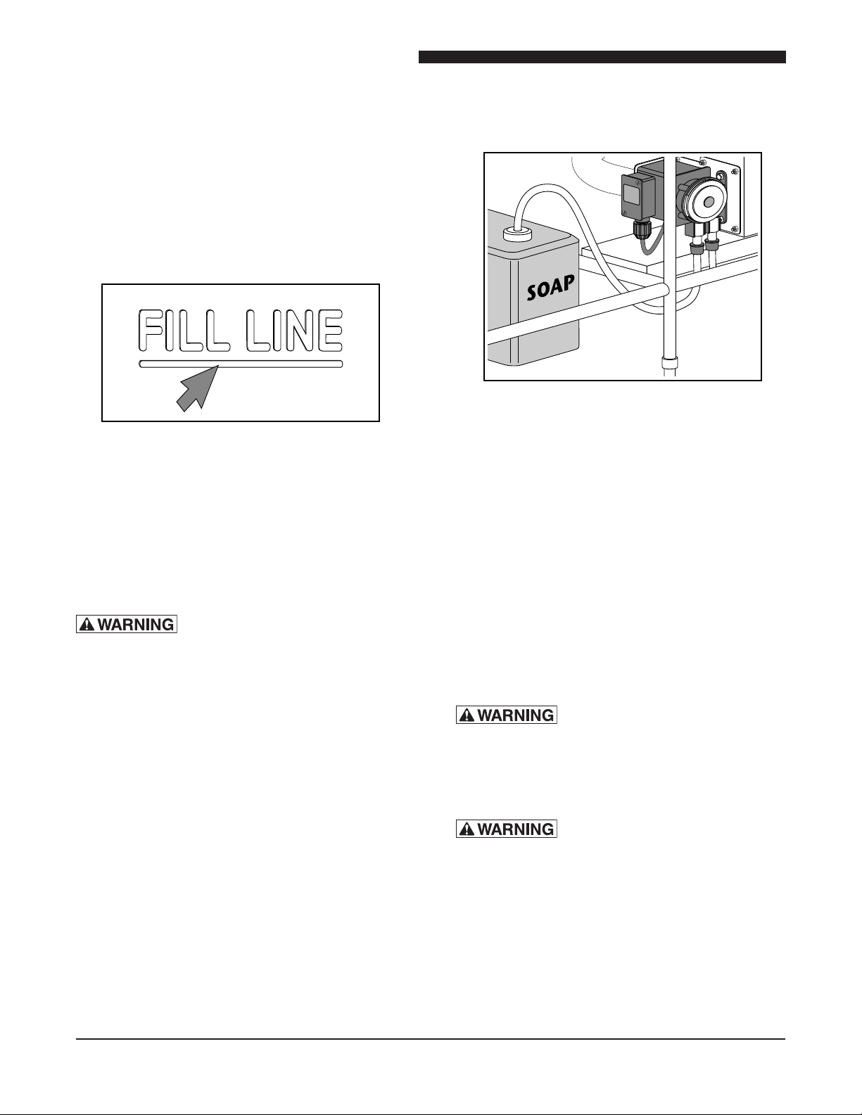
• PUMPS – The wash tank pumps will need to
be piped to a oor drain. This uses a ½” NPT
connection.
Pump
Pipe this connection
to floor drain
Bottom View of Pump Assembly

7
Installation and Operation of X-STREAM WASH
• Any plumbing overows for the unit are shipped
uninstalled and will need to be installed during
installation. See below for a depiction of the main
tank overow (Note: A main tank overow is an
option and is not provided on some units).
F. XSTREAM WASH OPTIONS
ITEM PART NAME PART
NO.
1 Scrap Basket, X-Stream Engine,
26.5"
115749
2 Scrap Basket, X-Stream Engine,
28"
115650
3 Pan Rack, Fixed, 26.5" Wide by
60" Long Unit
115800
4 Pan Rack, Fixed, 28" Wide by
60" Long Unit 1
115801
5 Pan Rack, Adjustable, 26.5"
Wide by 36" Long Unit
115811
6 Pan Rack, Adjustable, 26.5"
Wide by 42" Long Unit
115812
7 Pan Rack, Adjustable, 26.5"
Wide by 48" Long Unit
115813
8 Pan Rack, Adjustable, 26.5"
Wide by 54" Long Unit
115814
9 Pan Rack, Adjustable, 26.5"
Wide by 60" Long Unit
115815
10 Pan Rack, Adjustable, 26.5"
Wide by 72" Long Unit
115816
11 Pan Rack, Adjustable, 28" Wide
by 36" Long Unit
115817
12 Pan Rack, Adjustable, 28" Wide
by 42" Long Unit
115818
13 Pan Rack, Adjustable, 28" Wide
by 48" Long Unit
115819
14 Pan Rack, Adjustable, 28" Wide
by 54" Long Unit
115820
15 Pan Rack, Adjustable, 28" Wide
by 60" Long Unit
115821
16 Pan Rack, Adjustable, 28" Wide
by 72" Long Unit
115822
17 Pan Rack, Drop-in 115891
18 Basket, Skewer 115833
19 Basket, Utensil 115653
DRAIN
EXTRA TUBING
USED ON 60" & 72"
TANKS ONLY
COUPLES
ELBOW
WASH TANK
Overow Kit (Optional)
E. ELECTRICAL CONNECTIONS
: Electrical Hazard – May result
in electrical shock, burns, or death.
CAUTION
: Terminal block is phase sensitive.
Improper phase can cause incorrect pump
rotation. Pump rotation must be veried during
installation.
Your unit is supplied for connection to a 208, 240 or
480 volt grounded circuit. The electric motor, indicator
lights and control circuit are connected internally and
require no secondary power supply.
Before making any connections to these units, check
the rating plate to ensure that the voltage and phase of
the unit is compatible with the electrical supply. When
installing, all units must be electrically grounded in
accordance with local codes, or in the absence of local
codes, with the National Electrical Code, ANSI/NFPA
70 (in Canada - CSA Std. C22.2). Wiring diagrams
are located in the control compartment area of the
unit. Standard wiring schematics are also provided
with this manual.
To ensure service reliability and safety, use water-tight
connections and the proper wire gauge.Awire diagram
is located inside the control panel lid and also at the
back of this manual.

Installation and Operation of X-STREAM WASH
8
IV. OPERATION INSTRUCTIONS
A. INITIAL STARTUP
A-10 Fill Tanks with Water
• WASH TANK – Fill wash tank with hot water to the
marked Fill Line. The water temperature should be
110˚ to 115˚ F (43˚ to 46˚ C).
Fill Line
• RINSE TANK – If equipped, ll the rinse tank
with hot water to the marked Fill Line. The water
temperature should 75˚ to 80˚ F (24˚ to 27˚ C).
• SANITIZE TANK – If equipped, ll the sanitize
tank with hot water to the marked Fill Line. The
water temperature should 75˚ to 80˚ F (24˚ to
27˚ C).
: Do not connect to hot-water
supply exceeding a temperature of 115°F (46°C).
A-20 Add Soap / Chemicals
• WASH TANK – If your unit is equipped with the
soap injection option, then make sure that the
soap pump pick up tube is inserted into the soap
container. The soap will automatically be injected
into the wash tank. Otherwise, manually add the
soap into the wash tank in accordance with the
chemical supplier's instructions.
Soap Pump Installation
• SANITIZE TANK – If equipped, add the appropriate
sanitizing chemical to the sanitize tank. Consult
chemical supplier and your local health code.
A-30 Approved Chemicals
It is recommended that chemicals that are low to non
foaming, metal safe, and non-caustic be used in the
wash and sanitize tank.
Caustic chemicals are capable of burning, corroding,
or destroying living tissue and should not be used. If
you plan on using caustic chemicals, then a rolling lid is
required. If your unit did not come with a rolling lid, one
can be ordered from the factory. Contact information is
provided on the inside cover of this manual.
: Chemicals used in the wash
tank that do not have de-foaming capabilities
will not run properly and could damage the
machine. Consult your chemical supplier
before use.
: Chemical Hazard - could result
in serious injury or death. Always consult with
your chemical supplier and read all warning
labels before handling new chemicals.

9
Installation and Operation of X-STREAM WASH
B. PRE-SCRAPPING
Wares should be scrapped, NOT SCRUBBED, prior
to loading to remove heavy soils and debris. This will
improve wash results, reduce chemical costs and
reduce the number of water changes needed during
the day.
Use the scrapping sink (if equipped) or scrap the wares
in a separate waste area close to the unit. Do not scrape
wares directly into the wash tank.
Pre-Scrapping
C. LOADING WASH TANK
Pots and Pans
Pots, pans, mixing bowls, etc. can be placed into the
wash tank in any order.
Loading Wash Tank
NOTE: Pots and Pans that are stacked or nested
together during the wash cycle will not be cleaned
properly. Pause the cycle and move them apart from
one another.
Utensils and Silverware
Utensils and silver ware must be placed in a utensil
basket.
If your unit was not supplied with a utensil basket, one
can be ordered from the factory. Contact information
is provided in the Customer Assistance section of this
manual.
To use the utensil basket, simply hang the basket over
the side of the wash tank, place the utensils and silver
ware in the basket, and run a wash cycle.
Hang
Silverware
Basket
Utensil Basket Placement
: To prevent bodily injury never
load knives or other sharp objects into the
machine.
Sheet Pans
Load sheet pans as described below to ensure the
best washing methods.
If your unit was supplied with a sheet pan rack, place the
rack into the wash tank in a vertical position (opening
on top). Load the rack with sheet pans, and then pivot
the rack to a horizontal position.
To load sheet pans without the rack, insert the sheet
pans into the wash tank one at a time with the baking
side up. Place the pans in an alternating crisscross
pattern, so as not to have them nest inside of each other.

Installation and Operation of X-STREAM WASH
10
It is recommended that not more than 10 to 12 pans
be placed in the wash tank during a wash cycle.
If your unit did not come with a sheet pan rack, one
can be ordered from the factory. Contact information
is provided in the Customer Assistance section of this
manual.
D. START THE WASH CYCLE
After the wash tank has been loaded, press the cycle
start button. Which button you press will be determined
by which controller that has been installed on your
unit. See the Control Panels section of this manual
for more details.
Unload Wash Tank
The display will indicate that the items are clean when
a wash cycle has been completed. At this time the
system will switch to a holding cycle. This cycle has
slower water movement that will keep grease and
soiled sediments from falling back onto the items that
were just cleaned.
Remove the clean items from the wash tank and dip
into the rinse tank to rinse off any soap or soil residue.
Place items into Rinse Tank
Place items into the sanitize tank and soak according to
the chemical supplier's instructions and in accordance
with local health code.
Remove the item and allow to air dry when sanitization
is complete.
Soak in
Sanitizer
Place items into Sanitize Tank
E. CONTROL PANELS
E-10 Identifying Your Control Panel
There are two types of control panels used, the K1000
and the K5000. Use the diagrams below to determine
which control you have.
START
STOP
TEMP
K-1000 CONTROL CENTER
Heater
Alarm
Change Water
Soap
WARNING
Hazardous voltage.
Disconnect power before
servicing machine.
!
®
Your Solutions Partner
®®
(800) 735-3853
K-1000
K-5000

11
Installation and Operation of X-STREAM WASH
E-20 K1000 Control Panel
START
STOP
TEMP
K-1000 CONTROL CENTER
Heater
Alarm
Change Water
Soap WARNING
Hazardous voltage.
Disconnect power before
servicing machine.
!
®
Your Solutions Partner
®®
(800) 735-3853
K1000 Control Panel
Mylar Buttons
TEMP Button Press to set or display the wash tank's running temperature. When pressed, the display
will toggle between SP and 115 (115 represents a temperature set point value and may be different
on your display), at this time you can press the Up and Down Arrow buttons to change the set point
temperature. Once changed, press the Temp button again to lock in the new value.
Down Arrow Button Pressing this button, while not in the temperature set point mode, will display
the time remaining before a mandatory water change. Pressing this button while in the temperature set
point mode, will lower the temperature set point setting.
Up Arrow Button Pressing this button, while in the temperature set point mode, will raise the
temperature set point value. Pressing this button while in the wash mode will display the heater's
sheath temperature.
START/STOP Button Pressing this button will toggle on and off the circulation pumps.
Mylar Indicator Lights
Heater
Heater light will illuminate whenever the wash tank’s heater is powered on.
Alarm
Alarm light will illuminate whenever an alarm has occurred.
Change Water
Change Water indicator light will ash when it is time to change water. The display will show drn.
Soap
Soap indicator light will illuminate whenever the soap pump is powered on.
TEMP
START
STOP

Installation and Operation of X-STREAM WASH
12
K-1000
Basic Operation
When you rst power up to use your wash tank, the
display will show FIL, ll the wash tank to the water ll
line (see the INITIAL STARTUP section).
Once the tank has been lled, press the START/STOP
button to start the continuous wash cycle. Soap will be
dispensed automatically into the wash tank.
During the wash operation, the display will show current
water temperature and the heater light will cycle on
and off as the heater is maintaining the preset water
temperature.
The START/STOP button can be used to toggle on
and off the circulation pumps. During a pause state,
the heater is still in operation and maintaining the water
temperature.
After a certain amount of time, the water is considered
dirty and the circulation pumps will turn off, the display
will show drn, and the change water indicator light will
ash.
NOTE: Pressing the Down Arrow key will display
the time remaining before a water change is
required.
After the water has been drained, the display will
show FIL. You are now ready to start another wash
cycle.
Changing Temperature Set Point
The temperature set point is the water temperature
setting for the wash tank and is the only parameter
that can be set by the operator. If the TEMP button is
pressed once, the display will switch back and forth
from SP and 115 (115 represents the temperature
setting and may be different from your display).
Use the Up or Down buttons to change the temperature
setting. Once set, press the TEMP button to lock in the
new value.
NOTE: If no button is pressed within three seconds,
then your display will revert back to the way
it was before the TEMP button was pressed.
If the temperature setting was changed and
the TEMP button was not pressed, then the
temperature setting will remain unchanged.
Reset Change Water
The Change Water ag is cleared whenever the
heater’s sheath temperature rises above its set point.
In the case of a heater failure this ag cannot be reset
automatically. To manually reset this ag you will need
to hold down the Up button and START/STOP button
simultaneously for approximately 15 seconds. The
controller will then enter the
FIL
state.
Temperature Sensor Fault
If the water or heater sheath temperature sensors should
fail, the controller will indicate the fault by taking the
controller to the
FIL
state. The alarm light will be on,
the heater will be disabled, and the circulation pump
will be off.
After the sensor(s) have been replaced, normal
operation is resumed by exiting the
FIL
state.
Alarms
Alarm 1 is associated with the heater’s sheath
temperature, and is triggered when the temperature
rises above the value set in
AL.1
(see chart above).
Alarm 2 is associated with the wash tanks water
temperature, and is triggered when the temperature
rises above the value set in
AL.2
(see chart above).
When one of these alarms is activated, the circulation
pump will turn off and the alarm indicator light will be
illuminated. The controller will enter the
FIL
state.

13
Installation and Operation of X-STREAM WASH
Programming – Controls Supplied After
12/01/2013
The programming mode can be accessed by holding the
TEMP and START
STOP buttons simultaneously for 5 seconds. The
display will switch back and forth between SP and 115.
The following parameters can be set in the
programming mode:
Parameter Description Default Value
SP Set Point
Temperature
Default
Temperature is
115°F
t1 Change Water
Cycle Time
Default Cycle
Time is 4:00
(H:MN)
t2 Soap
Dispensing
Delay Time
Default Delay
Time is 0:45
(M:SC)
t3 Soap
Dispensing Time
Default
Dispensing
Time is 1:30
(M:SC)
F/C Celsius/
Fahrenheit
Selection
Default
Temperature
Units is
Fahrenheit (F)
The and buttons are used to increment and
decrement parameters.
The TEMP button is used to scroll through the
parameters.
Pressing the TEMP button after the last parameter
saves the parameters and exits programming.
Programming – Controls Supplied Prior To
12/01/2013
Supervisor Mode
The supervisor mode can be accessed by holding the
TEMP and START/STOP buttons simultaneously for 3
seconds. The display will toggle OPr and OP.b.
Pressing the Up or Down buttons will toggle between
OP.b, OP.5, CPI, and CnF.
Quick Helpful Hints:
To enter and exit Modes: Press the Temp and
Start/Stop buttons simultaneously.
To scroll through the parameters: Press the Temp
button.
To scroll through the modes or change values
for a parameter: Press the Up and Down button
arrows.

Installation and Operation of X-STREAM WASH
14
Setup Mode – OP.S
Enter the supervisor mode and press the Up or Down
buttons until OP.5 appears in the display.
Press the TEMP button to select.
When prompted for a password PSS and three dashes
toggle. The three dashes is where you enter the
password of 55.
Use the Up and Down buttons to select 55.
Press the TEMP button to enter and lock the password
and advance.
Press the TEMP button to advance between the
parameters that are available, see parameter table.
(The parameter name and its value will be swapped
in and out of the display.)
Press the Up and Down button to change the
parameters value.
Once a value has been changed, press the TEMP key
to lock in this value and move on to the next parameter.
NOTE: If you do not press the TEMP button within 3
seconds after changing a parameters value,
the new value will not be saved. Push TEMP
button to access parameters again.
IMPORTANT
Before you save and exit, you need to scroll
through the parameters back to the temp display
before pressing the Temp and Start/Stop buttons
simultaneously.
To save and exit the supervisor mode, press TEMP
and START/STOP buttons simultaneously for 3
seconds and OPr appears in the display.
Press the Down button once and OP.b appears in
the display.
Then press the TEMP button and FIL appears in the
display and you have exited the supervisor mode.

15
Installation and Operation of X-STREAM WASH
Setup Mode Parameter Table
Parameter Mne-
monic
Parameter
Name
Description Table 1
Default Value
(Fahrenheit)
Table 2
Default Value
(Celsius)
Units
Setpoint Temperature Set
Point 115°F 46°C Degrees
Timer 1 Change Water
Cycle Time 4.00 4.00 H:MM
Timer 2 Soap Dispensing
Delay Time 0.45 2.00 M:SS
Timer 3 Soap Dispensing
Time 1.30 0.30 M:SS
Alarm 1 Alarm 1 Set
Point 250°F 107°C Degrees
Hysteresis Alarm 1 Hyster-
esis 0.1 0.1 %
Alarm 2 Alarm 2 Set
Point 160°F 72°C Degrees
Hysteresis Alarm 2 Hyster-
esis 0.1 0.1 %
Hysteresis On/Off Hyster-
esis 0.1 0.1 %
Range Low Set Point
Low Limit 100°F 38°C Degrees
Range High Set Point High
Limit 125°F 52°C Degrees

Installation and Operation of X-STREAM WASH
16
Conguration Mode – CnF.
Enter the supervisor mode and press the Up or Down
buttons until CnF. is displayed. Press the TEMP button
to select.
When prompted for a password (PSS), use the Up
and Down buttons to select 415. Press the TEMP
button to enter in the value. Press the TEMP button
to toggle between the parameters that are available,
see parameter table below.
The parameter name and its value will be swapped in
and out of the display. Press the Up and Down button
to change the parameters value. Once a value has been
changed, press the TEMP button to lock in this value
and move on to the next parameter. If you do not press
the TEMP button within three seconds after changing
a parameters value, the new value will not be saved.
Exit the supervisor mode when done with the setup mode.
NOTE: See Supervisor Mode section on how to exit.
Conguration Mode Parameter Table
Parameter
Mnemonic Description Table 1 Default
Value (Celsius)
Table 2 Default
Value (Fahrenheit) Units
P1 Input table 2 10
P2 Low scale range of sensors 0°C 32°F Degrees
P3 High scale range of sensors 282°C 540°F Degrees
P4 Output 1 control action rEu rEu
P5 Output 2 function I I
P6 Output 2 alarm type H.A. H.A.
P8 Alarm 1 standby function OFF OFF
P11 Auto-ranging display OFF OFF
P12 Filter sensor values On On
P22 Output 3 function I I
P23 Output 3 alarm type H.A. H.A.
P25 Alarm 2 standby function OFF OFF
P33 Access to OP.S mode 55 55
P35 Access to CnF. mode 415 415
P36 Access to I.CL mode 415 415
Loading Celsius or Fahrenheit Tables
The controller contains two default parameter tables.
Table 1 is used for Celsius operation, and Table 2 is
used for Fahrenheit.
To load one of the default tables, enter the conguration
mode (See instructions listed in the Conguration Mode
–
CnF
section listed above). When
CnF
is displayed,
press both the Up and Down buttons simultaneously.
The display will show
dL.F
. Press the Up or Down
buttons to display
dL.1
for table 1 (Celsius), or
dL.2
for table 2 (Fahrenheit).
Press the TEMP button to enter in your selection. The
display will show
Ld.t
. This indicates that the loading
procedure has been initiated and after approximately
1 second, the loading will be nished and the display
will revert back to
CnF
.
Exit the supervisor mode when done. NOTE: See
Supervisor Mode section on how to exit.

17
Installation and Operation of X-STREAM WASH
E-30 K5000 Control Panel
K5000 Control Panel
Timer Operation
The change water timer (
t
) will retain its current
count when the washer is stopped or when power is
disconnected from the controller.
The soap delay timer (
t2
) allows for a delay before soap
is dispensed into the wash tank. This allows the soap
to be added to a wash tank when it is full of water and
the circulation pumps are running.
The soap dispensing timer (
t3
) determines the time for
soap dispensing. A time of
0.00
will bypass the soap
dispensing process.
Display Software Version
To display the software version, enter the conguration
mode (See instructions listed in the Conguration Mode
–
CnF
section listed above). When
CnF
displayed,
press the DOWN button. The software version number
will be displayed and should look something like
d.17
.
Press the DOWN arrow button again to return back to
the
CnF
display.
Exit the supervisor mode when done. NOTE: See
Supervisor Mode section on how to exit.
Display Lamp Test
A lamp test can be started by pressing the DOWN and
TEMP buttons simultaneously. During the lamp test, the
controller functions normally, but all display segments
and status lights ash. Pressing the TEMP button again
will return back to the normal operation display.

Installation and Operation of X-STREAM WASH
18
K-5000 OPERATION INSTRUCTIONS
TOUCH SCREEN CONTROL DEFINITIONS
Status Bar
Info Button
Touch to access recipe programming,
diagnostics, training materials, cleaning
procedures and other tools.
Main Screen
Status Bar
Recipe Buttons
Turns Blue when
recipe is selected.
Power/Cancel Button
Continuous press will
canel active recipes
and change to idle
screen (below).
Recipe Start Button
Touch to start selected
recipe.
Sanitizer Start Button
If equipped press play
to start the sanitizer
system.
AUDIBLE ALARMS
The K-5000 has various audible alarms as shown below.
1 chirp Keystroke acknowledgement
2 short chirps Recipe complete notication
Wash Water Temperature
Displays current wash
water temperature.
Use +/- to adjust wash
water temperature.
Idle Screen
Shown after the display
is idle for 10 minutes

19
Installation and Operation of X-STREAM WASH
A. DAILY BROILER START-UP
1. Turn the ON/OFF power switch to the ON (I) position. The boot screen will display and then
automatically transition to the main off screen.
Figure: Boot Screen Figure: Main Screen
2. Touch a recipe button.
3. Allow to the sink to test & validate the wash water is full & at a safe
Figure: Ready Screen - Water
Temperature Stable Ready to
Start Recipe
Figure: Testing Water Temperature
Recipe Start Button
Touch to start or press
Select Recipe
Touch to select
active recipe

Installation and Operation of X-STREAM WASH
20
B. COOK PRODUCT
1. After startup is complete the Ready Screen appears. The ability to begin a wash recipe is now
available through the press of the programmed recipe buttons. After the Recipe Start Button is
pressed the current recipe count down timer will display with a progress bar shown below.
Figure: Recipe Active Screen
2. When the recipe is complete the K-5000 will beep twice until the display is reset by press & hold
the Power/Cancel Button. The display now reverts back to the Main Screen above.
Wash Recipe Progress Bar Press & Hold to Cancel
Current Recipe
Figure: Recipe Active Screen MM:SS reamin.
Table of contents
Other Duke Kitchen Appliance manuals