IM 701210-07E
4
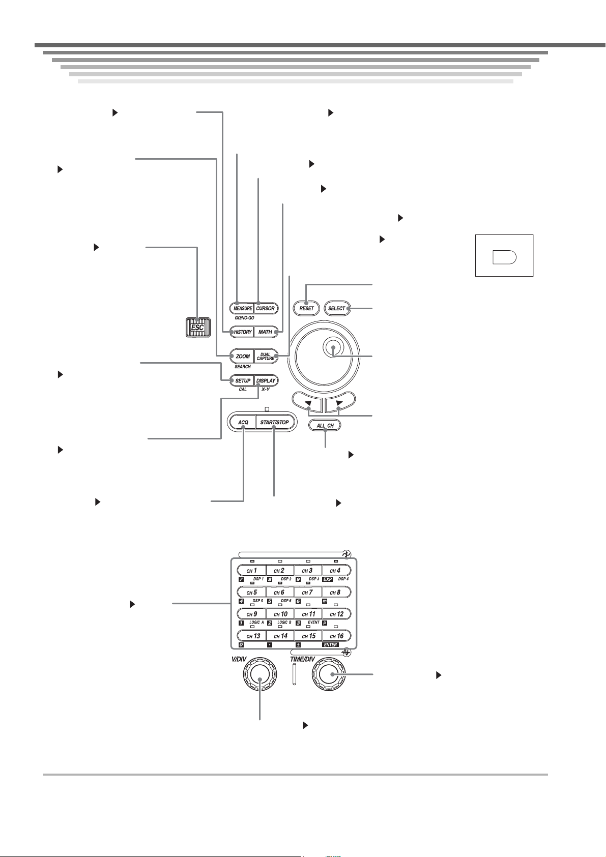
Front Panel Controls
ACQ key Sections 5.14, 7.2 to 7.4, and 7.6
Displays a menu used to set the w aveform acquisition
mode.
HISTORY key Sections 11.1 and 11.2
Displays a menu used to display past data using
the history memory function.
(SHIFT+) DISPLAY key
Sections 8.1 to 8.13
Displays a menu related to the screen display.
Pressing the SHIFT key followed by the DISPLAY
key displays a menu related to X-Y display.
SELECT key
Confirms the menu item that you selected using
the jog shuttle.
Jog shuttle
Used to change settings and move the cursor.
Turn the shuttle ring to change the amount of
change according to its angle.
(SHIFT+) MEASURE key Sections 11.6 and 11.7
Displays a menu used when performing automated measurement of waveform parameters or cycle
statistical processing. Pressing the SHIFT key followed by the MEASURE key displays a menu
related to GO/NO-GO determination.
CURSOR key Section 11.5
Displays a menu used when performing cursor measurements.
Arrow keys
Moves the cursor left or right.
ALL CH key Section 5.13
Displays a pop-up window containing a list of settings similar to those
displayed on the menu when one of the keys from CH1 to CH16 and
DSP1 to DSP6 (/G3 option) keys is pressed.
START/STOP key Section 7.1
Starts/Stops waveform acquisition according to the trigger mode.
Waveform acquisition is in progress when the indicator above the key is illuminated.
RESET key
Resets the value entry to the initial value (default).
(SHIFT+) SETUP key
Sections 4.4 to 4.6
Displays a menu related to initialization and auto
setup. Pressing the SHIFT key followed by the
SETUP key displays a menu related to calibration.
ESC key Section 8.13
Used to clear the menu. When a menu
is cleared using the ESC key, the
channel information appears. If you
press the ESC key again, the channel
information is cleared, and the
waveform display area is expanded
horizontally.
(SHIFT+) ZOOM key
Sections 8.5 and 11.4
Displays a menu related to the zoom display of
waveforms. Pressing the SHIFT key followed by
the ZOOM key displays a menu related to data
search (search & zoom function). DL750: DUAL CAPTURE key Section 7.6
Displays a menu related to the dual capture function.
DL750P: RECORDER key Chapter 9
Displays a menu related to the recorder mode.
Pressing the SHIFT key followed by the RECORDER key
displays a menu related to the dual capture function.
MATH key Chapter 10
Displays a menu related to the waveform computation.
RECORDER
DUAL
CAPTURE
On the DL750P
VERTICAL
HORIZONTAL
V/DIV knob Section 5.3
You can set the voltage sensitivity using this knob. Before turning it press a key from CH1
to CH16 to select the target channel. If you change the setting while waveform
acquisition is stopped, the settin
takes effect when
ou restart the waveform acquisition.
CH1 to CH16 keys Chapter 5
Displays a menu used to turn ON/OFF the display
of each channel and set the vertical position,
coupling, probe type, offset voltage, bandwidth
limit, expansion or reduction of the vertical axis,
linear scaling, and waveform labels. The indicator
above each CH key illuminates when the
corresponding channel is ON. In addition,
pressing the SHIFT key followed by a CH key
displays a menu corresponding to the purple
characters indicated to the right of each key.
Pressing the NUM KEY followed by a CH key
causes the gray value marked below and to the left
of each key to be entered.
TIME/DIV knob Section 5.2
This knob is used to set the time axis scale. If you
change the setting while the waveform acquisition
is stopped, the setting takes effect when you restart
the waveform acquisition.
Front Panel Controls
Front Panel Controls